Introduction
In this article we will see how to work with the Text Mesh Pro components from a Script, in addition you will find a video from the channel in which we will create a TEXT OBJECT to display in a Canvas and another Text Mesh for the 3D space and we will create a Script inside which we will modify the text that these components show, as an extra we will also modify the color by code.
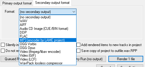
This is how you import TextMesh PRO tools in Unity and create a script to write Text Mesh PRO by code in Unity:

First Step: Create Text Mesh Pro objects for World Space or for the Canvas
You can use Text Mesh PRO to display a text in the user interface or to display text in the world (like a 3D model), for the first option you need to create Text from the UI menu, these kind of text should be placed inside a Canvas and it will be overlayed with the game view. You can find the Text for the worldspace in the 3D Objects menu.
Let’s analyze both cases
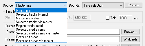
We start by creating the Text objects that we will later modify from a Script, we are going to create two types of Text Mesh Pro objects, one to use in the user interface and another to use as a 3D object in the scene.
Creating Text Mesh Pro Text for the user interface
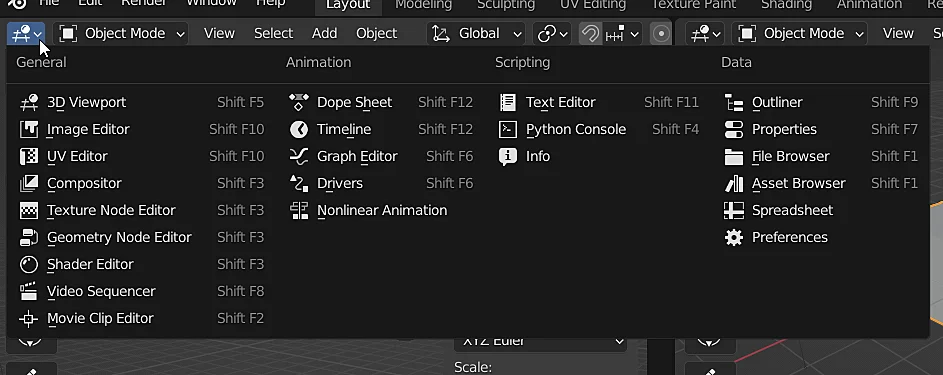
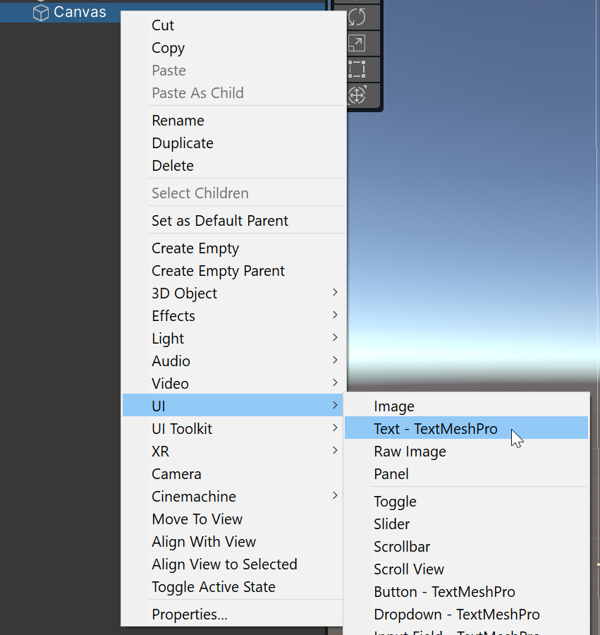
In Unity the Text Mesh Pro objects that are in the UI section must be placed as children of a Canvas object, so let’s assume that we already have one of these objects in the scene. To create a new Text Mesh Pro object we go to the hierarchy, right click on the Canvas (or any child object of the Canvas), go to the UI section and choose the “Text – Text Mesh Pro” option, as shown in figure 1.A.

Creating a Text Mesh Pro Text for World Space
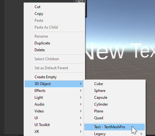
The other option to write text on the screen is to use a Text component of Text Mesh Pro as a 3D object and therefore located in a position in the world, this object will be found in the “3D Object” section of the creation window, as shown in figure 1.B.

First time using Text Mesh Pro
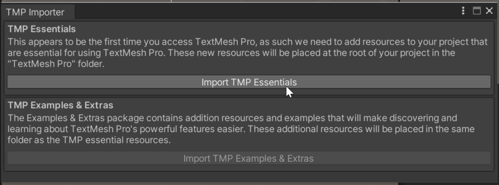
In case we have not configured Text Mesh Pro yet, we will get the window shown in figure 2 where we will be given the option to import the necessary components to use Text Mesh Pro, we click on “Import TMP Essentials“, as shown in figure 2. The second button to import examples and extras is optional.

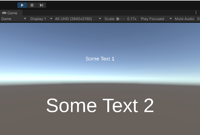
Result of the creation of objects
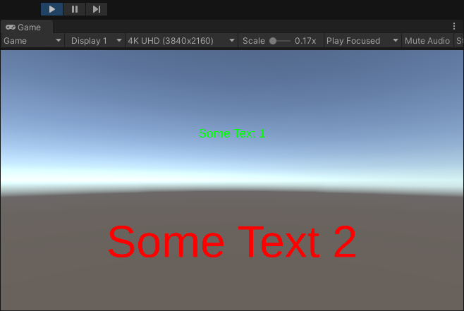
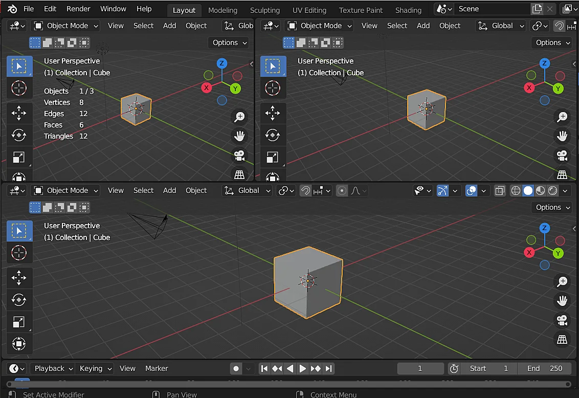
Once the objects were created, I made a few modifications in the inspector (font size, text) and the result is as follows:


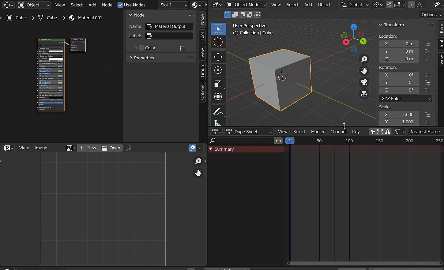
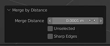
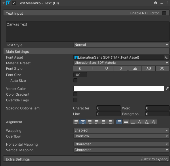
Once the objects have been created and Text Mesh Pro imported we can start using the Text Mesh Pro Text component from the inspector or write it through a Script. In figure 4 we see the Text component in the Inspector window, it has many more configuration options compared to the old text solution.
IMPORTANT
In figure 4 we see the field to edit the text that appears on the screen, currently has written the value “Canvas Text”, that is the field that we want to edit by code and to do it we will have to edit a variable called “text” that is define in that component.

Script for writing text in Text Mesh Pro component
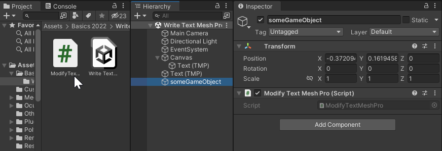
In order to write a Text Mesh Pro component by code I will create a script and assign it to some GameObject of the hierarchy, as shown in figure 5. In this case my script is called “ModifyTextMeshPro”, inside this script I will modify the texts.

Import TMPro namespace in our Script
To be able to use the Text Mesh Pro components comfortably, it is convenient to import the “TMPro” namespace by adding in the header of our script the line “using TMPro;” as shown in figure 6.


Declaration of the variables to be used
We are going to declare two variables of type “TMP_Text” where the references of the Text components that we want to modify will be stored, in this case the names of my variables will be “canvasText” and “worldText“, in these variables I will place the Text Mesh Pro Text components of the canvas and the world space respectively.
IMPORTANT DETAIL
The names “canvasText” and “worldText” are the names I chose for these variables, you can use any other name as long as it contains allowed characters.


Initialization of variables (Assignment of references)
The initialization of this type of non-primitive variables is crucial, if we do not take care of putting inside the variable the precise object we want to refer to, we will get a null reference exception.
There are many ways to initialize the variables, in this case I will do it in one of the simplest ways which is by dragging the GameObjects that contain the Text components I want to modify to the variable spaces in the inspector.


The declared variable does not appear in the inspector
In the case that the variable does not appear in the inspector it is usually because its visibility is private, it can be solved by declaring the variables as public as shown in figure 7, adding the word “public”, or they can also be declared as private but indicating that they are serialized by the inspector, as follows:
[SerializeField]
TMP_Text canvasText;
Or:
[SerializeField]
private TMP_Text canvasText;
Another reason why the variables do not appear in the inspector can be when there are errors in console and the changes made in the scripts are not updated, to solve this we will have to solve all the errors that there are in console, once made this Unity will compile and the new modifications will appear.
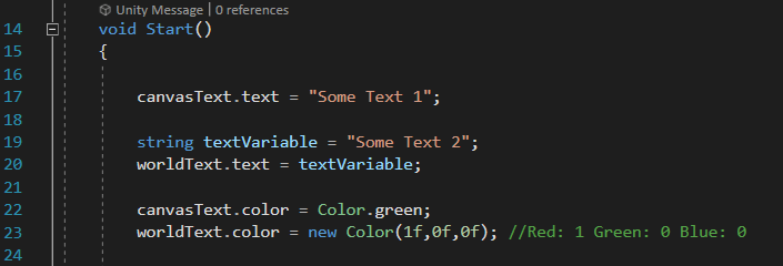
Code instructions for modifying Text Mesh Pro text via Script and tests
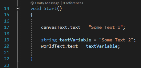
Once we have initialized the variables we can use them, in this case if we want to modify the text displayed by the Text Mesh Pro component, we must modify the variable “text” defined inside it, for this we use the dot operator that allows us to access the variables and public functions defined inside an object,


Extra: Change the color of a Text Mesh Pro text by code