In this article we will see how to show only the selected object in Blender and hide all the other objects, this is a simple trick that works for objects and also geometry, that is to say, we can select a couple vertices or faces and isolate that geometry from the rest and work better.
For a visual breakdown of this subject, you may find my video discussion helpful:
Procedure to isolate objects and geometry in Bleender
Let’s consider the situation we have in figure 1, in which we have a selected object that is surrounded by other objects, we would like to be able to visualize only the object we have selected and hide the rest, for that we can use the shortcut SHIFT+H, which results in what we can see in figure 2. To make visible again all the hidden objects we press ALT+H.
Fig. 1: A selected object in a scene with more objects.
Fig. 2: The selected object is displayed in isolation for better working.
Introduction
When we are Rigging and creating animations in Blender it is useful to be able to visualize the animation bones in front of the 3D model to make it easier to select and manipulate them, in this article we will see how to make bones always appear in front of everything, regardless of whether there are other objects in front of them.
All the IMPORTANT information is summarized in the following TUTORIAL FROM MY YOUTUBE CHANNEL
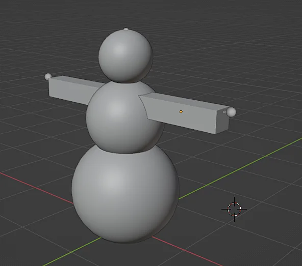
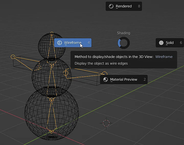
We start with a 3D model and its respective Armature object (animation skeleton), as shown in figure 1 the Armature is barely visible in solid mode, so let’s switch to Wireframe mode to be able to see and select the Armature, as shown in figure 2.
Fig. 1: In the scene we have a 3D model and an Armature object that is obstructed by the object.
Fig. 2: In Wireframe mode you can see objects that are hidden behind other objects.
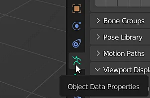
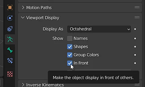
With the Armature selected we go to the properties window with the icon shown in figure 3 and in the “Viewport Display” section we check the “In Front” checkbox.
Fig. 3: With the Armature selected, go to its properties tab.
Fig. 4: In the “Viewport Display” section, check the “In Front” checkbox to display the animation bones in front of the objects.
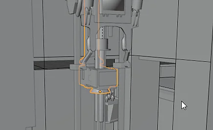
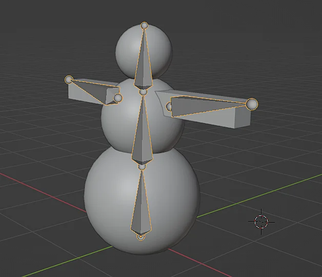
Now the animation bones are always visible from any perspective no matter if they are inside the model or even if there are other objects in the scene in front of them, making Armature easy to use.
Fig. 5: The animation skeleton is now visible even if it is inside the 3D model.
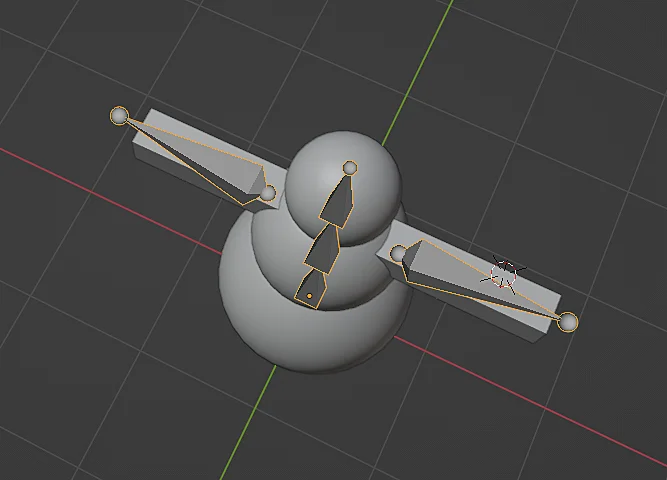
Fig. 6: In this other view we see how the Armature is inside the model but still visible.
Introduction
Sometimes we are looking at a certain part of a scene in Blender and we need to visualize an object that is located in other place, if we don’t have so much experience using Blender this can be a big problem because controlling the view and the render camera could be quite challenging.
The TIP we are going to see in this article could save you in more than one time, we will see how to quickly focus the view on an object and also how to make the rendering camera move and focus a target object.
Video tutorial on how to focus the view on an object in Blender
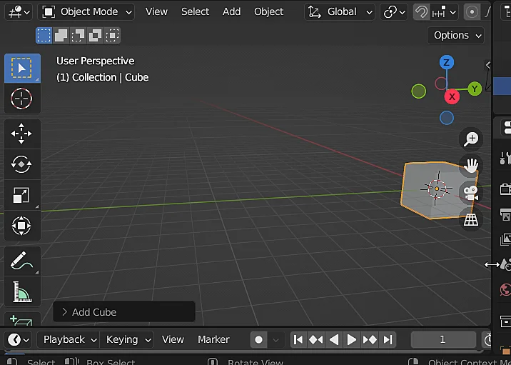
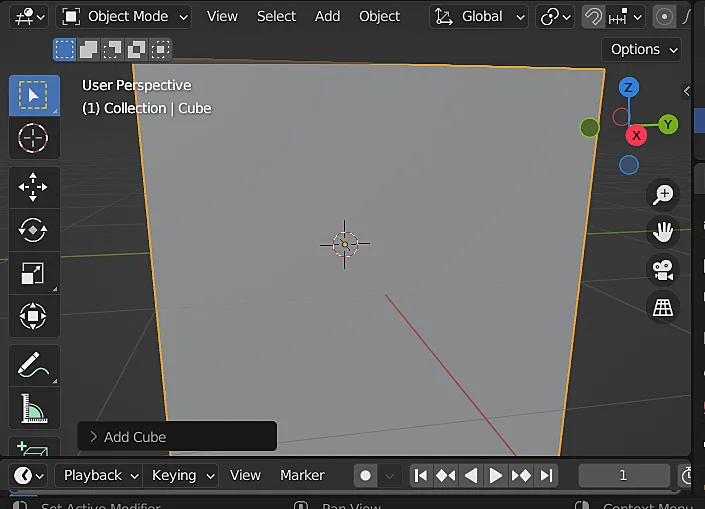
In order to quickly FOCUS the view on an object in Blender we select the object and press the dot key on the numeric keypad (Numpad .), with this we go from the situation shown in figure 1 below to figure 2, in which the view is centered on the origin of the selected object. If you don’t have a numeric keypad you can select the object, click on “View” and then choose the “Frame Selected” option, this will focus the view on the selected object aswell.
Fig. 1: We start from this situation in which the selected object is not centered in the view.
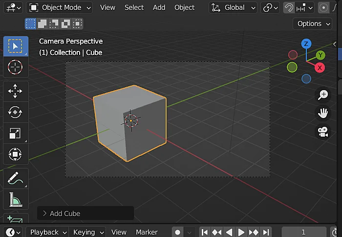
Fig. 2: Pressing the dot on the numeric keypad moves the view to focus on the origin of the selected object.
Focus the camera on an object in Blender
The idea is similar in this case, but we want to move the RENDER CAMERA so that is focused on the selected object.
We start from the situation shown in figure 3 below in which we are seeing the camera perspective, the camera view can be activated with the zero key on the numeric keypad (Numpad 0).
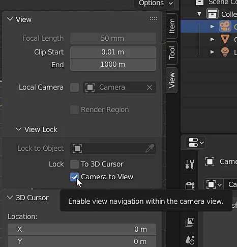
We go to the view tab shown in figure 4 and activate the “Camera to View” checkbox, this will allow us to control the position and orientation of the rendering camera by zooming, panning and rotating the view. In case you do not see the View panel is because it is hidden, it can be displayed with the N key or the arrow icon that is observed in the upper right corner of Figure 3 (slightly above and to the right of the green circle with the letter Y).
Fig. 3: We start from this situation in which the rendering camera is not centered on the selected object.
Fig. 4: Option to lock the camera to the 3D view.
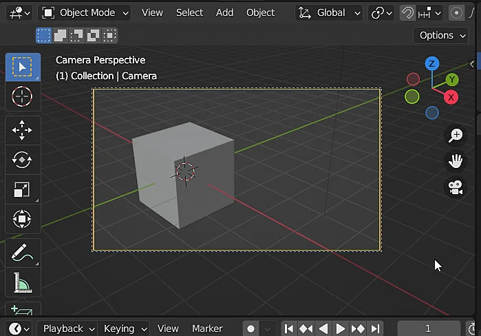
When the camera is locked to the 3D view you can see the red dotted box, now to center the camera on the object we select the object and press the dot on the numeric keypad, so we go from the situation in figure 5 to the situation in figure 6.
Fig. 5: When the camera is locked to the 3D view it shows a red dotted line.
Fig. 6: Pressing the dot on the numeric keypad centers the view on the origin of the selected object.
Introduction
In both Blender and Unity you can establish a hierarchical relationship between objects in the scene, in Blender this is reflected in the Outliner while in Unity we see it in the Hierarchy window. If we have an object that is related to a second object called parent, when the parent object is transformed, meaning by transformation the state of position, rotation and scale or a change in these properties, this transformation also applies to the child object since the properties defined in this one are calculated relative to the parent. In this article we see how to parent objects in Blender and then how to remove that parent relationship.
For a visual breakdown of this subject, you may find my video discussion helpful.
How to parent objects in Blender – Detailed process
We start with a scene containing two objects, “Object1” and “Object2” as shown in the Outliner window in Figure 1.
The first thing we are going to do is to select the objects we want to parent.
ATTENTION
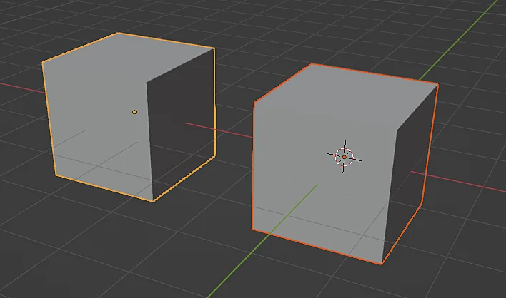
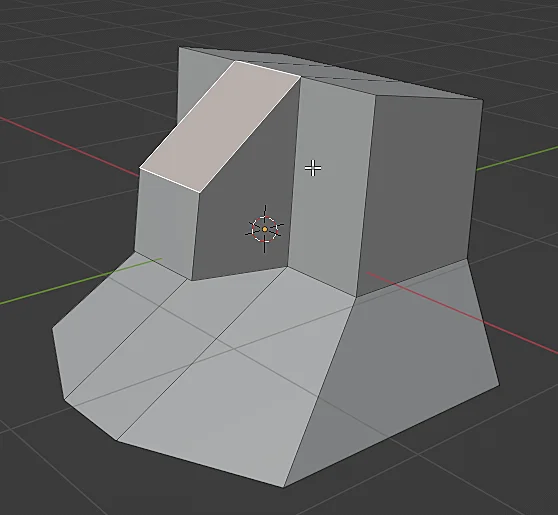
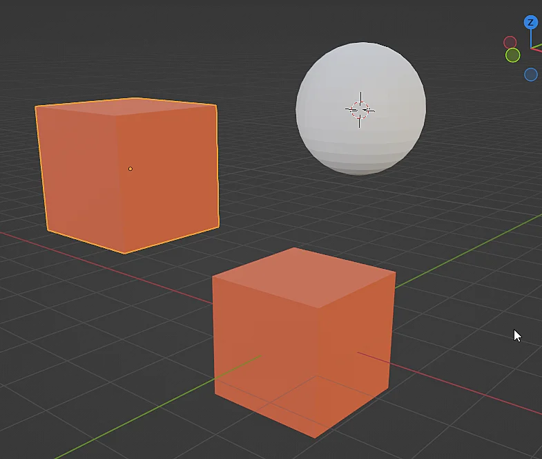
In figures 2 and 3 both objects have been selected but both cases are NOT EQUIVALENT, notice that one of the objects is highlighted in yellow, in the case of figure 2 it is the cube on the right while in figure 3 it is the cube on the left.
The object highlighted in yellow is the “Active Selection” and when we parent these objects the parent will be the object we have as the active selection.
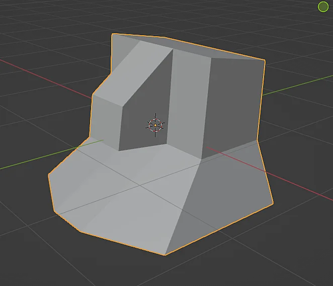
Fig. 1: In the scene we have two objects to be related.
Fig. 2: Both objects are selected, the active selection is the object on the right.
Fig. 3: Both objects are selected, the active selection is the object on the left.
To relate one or more objects to another parent object we press CTRL+P which displays the window shown in Figure 4 in which we can choose the type of relationship, in general I choose the option “Object (Keep Transform)“, which makes the child object calculates its local transformation from the origin of the parent object and also keeps the position in which it is.
Fig. 4: Window for parenting objects to the object that is the active selection.
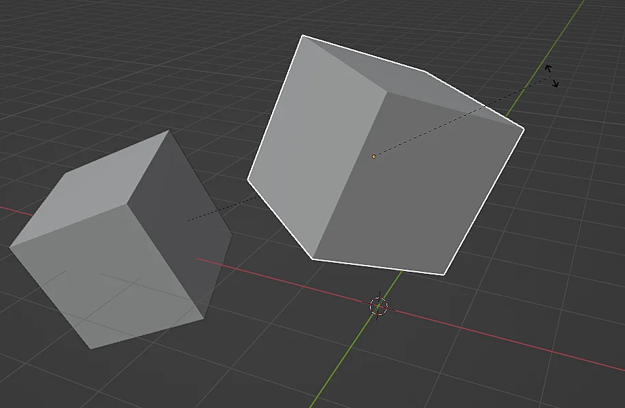
In figure 5 we see the result of applying a rotation to the parent object, the child object rotates as a whole due to the parent relationship. In figure 6 we see that we can rotate the child with respect to its own origin and this does not affect the parent object.
Fig. 5: When the parent object is rotated this rotation is transferred to the child objects.
Fig. 6: The child object can be rotated individually and this does not affect the parent object.
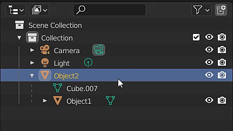
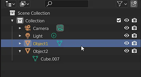
In the Blender Outliner we see the parent relationship that has been established, object 1 is now contained within object 2.
Fig. 7: In the Blender Outliner the relationship between these objects is reflected.
How to unparent objects in Blender – Detailed procedure
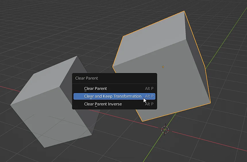
Starting from the previous objects that are related, we are now going to unparent the objects. To do this, select the object to be unparented and press ALT+P, the window shown in figure 8 appears, generally I choose the option “Clear and Keep Transformation” which removes the parent relationship and keeps the position, rotation and scale of the object. As shown in figure 9, now both objects are at the same hierarchical level.
Fig. 8: Window for removing an object’s parent relationship to other objects.
Fig. 9: In the Outliner we again have both objects at the same hierarchical level.
You have reach the end of the article, if it was useful consider subscribing to the channel!
The normals of 3D models are vectors that are used to know the orientation of each face of the model and have many utilities, mainly for the rendering of a 3D model, for example they allow to calculate how the model will be illuminated, how the light will bounce, how the shading will be; they are also used in physics for collisions, so it is important that the normals of our models are consistent with what we need, occasionally some normals of the model are pointing in the opposite direction and this brings problems. In this article we are going to see how to make visible the normals of a 3D model in Blender.
In the following video we see how to display NORMALS in Blender.
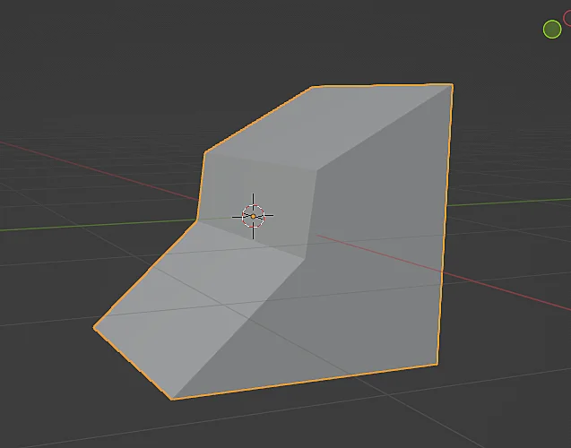
We start from a generic 3D model like the one in figure 1 and we are going to enter the edit mode, this is IMPORTANT because the normals can only be made visible from the edit mode and they are only displayed in the edit mode.
Fig. 1: 3D model selected in object mode in Blender.
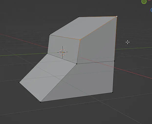
Fig. 2: The Edit Mode of a 3D model in Blender.
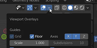
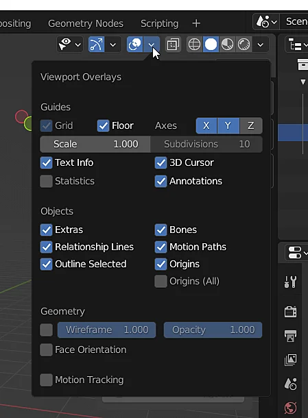
We click on the icon shown in figure 3, which displays a window that allows us to configure the elements that overlap in the 3D view window.
Fig. 3: Window of overlapping elements in the Viewport.
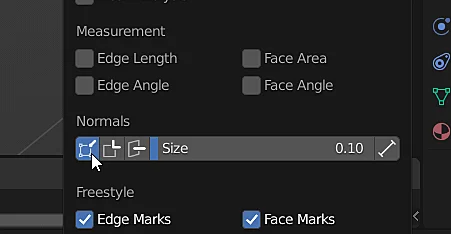
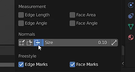
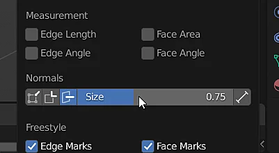
To show the normals we click on one of the icons in the “Normals” section, in general I am interested in seeing the normals in the center of the face, so I choose the option in figure 5, although sometimes I also use the option to show the normals at the vertices. Mathematically it does not make sense to talk about the normal vector to a point, but in the rendering the meshes consist of lists of vertices that form triangles and each vertex has a normal vector associated with it, those normals vectors are generally interpolated.
Fig. 4: Option to display the normals on the vertices of a 3D model in Blender.
Fig. 5: Option to display the normals in the center of the faces of a 3D model in Blender.
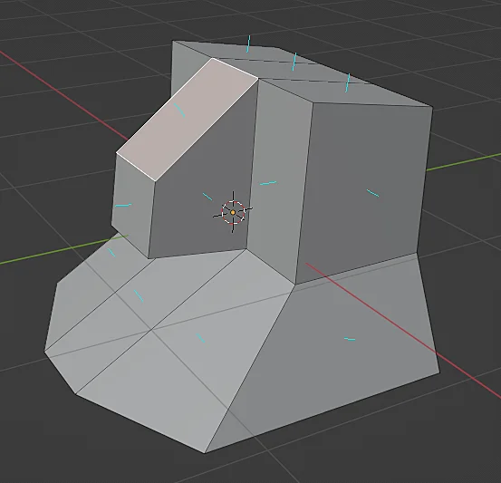
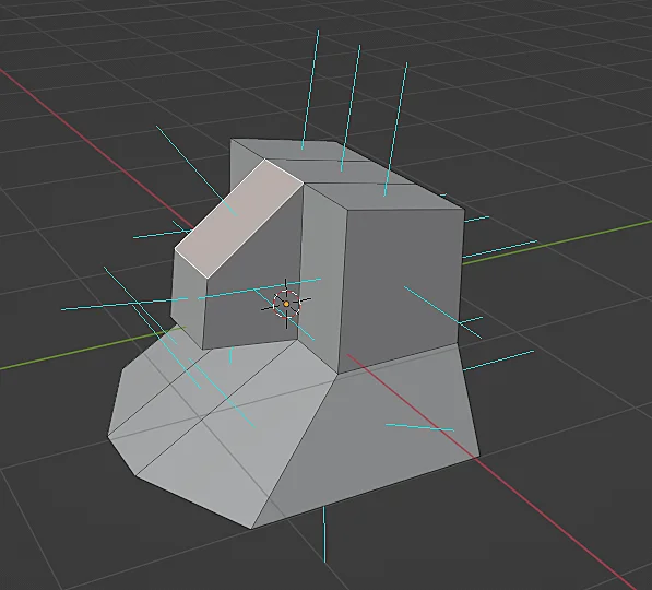
Figure 6 shows the normals in the center of the faces of the 3D model when in edit mode.
Fig. 6: The normals of the 3D model are now displayed in the center of the model faces.
Using the “Size” parameter we can change the length of the normals, as shown in Figure 8.
Fig. 7: Modification of the length of the normal vectors to be drawn.
Fig. 8: The normals of the 3D model are displayed longer.
Introduction
When modeling precision-based projects—such as replicating parts from technical schematics or preparing models for 3D printing—knowing the exact edge lengths in Blender is essential. Fortunately, Blender provides tools to display these measurements directly in the viewport. In this article, we’ll walk through how to enable edge length display for selected edges, ensuring accuracy in your workflow.
For a visual breakdown of this subject, you may find my video discussion helpful.
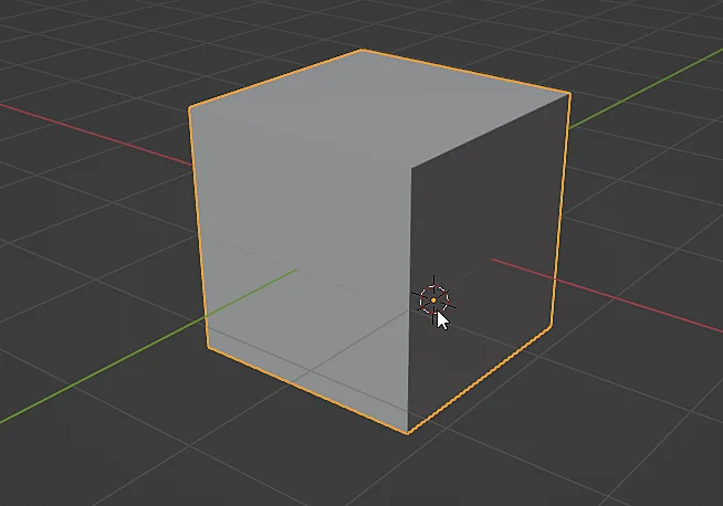
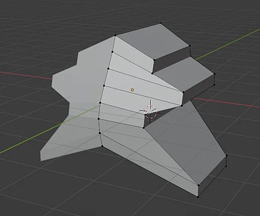
To begin, we’ll use the 3D model displayed in Figure 1. Edge length measurements can be enabled in either Object Mode or Edit Mode, but for this demonstration, we’ll switch to Edit Mode with the model selected. Once in Edit Mode, simply select any edge—as illustrated in Figure 2—to proceed with displaying its length.
Fig. 1: 3D model whose edge length needs to be known.
Fig. 2: In edit mode an edge of the model is selected.
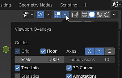
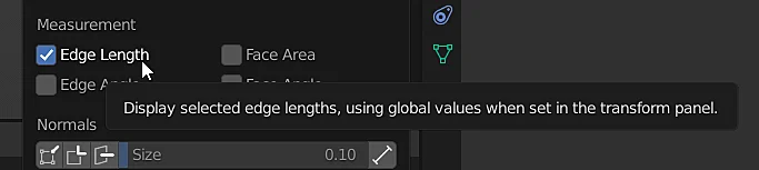
In Figure 3, locate the Viewport Overlays icon (indicated by the cursor). Clicking this icon opens a settings panel where you can control which visual elements appear in Blender’s 3D workspace. From here, simply enable the Edge Length checkbox—as demonstrated in Figure 4—to display measurements directly on your model.
Fig. 3: Window of overlapping elements in the Viewport.
Fig. 4: Option to display the edge lengths of a model in Blender.
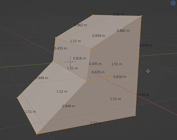
Once enabled, the edge lengths will appear on your selected model, as visible in Figure 5.
Fig. 5: The 3D model now has the lengths of the selected edges overlapped in the Viewport.
Introduction – Why mirror objects in Blender?
In this article we are going to see how to prepare a 3D model to use the “Mirror” modifier in Blender, which allows us to model with symmetry with respect to one or more axes.
When mirroring an object in Blender we can focus on creating just one side of the model and then Blender, in a procedural way through a “modifier”, will produce the rest of the model based on one or more symmetry axes, this makes it much easier to create symmetrical pieces, as it could be the basics of a human face, once you have covered the basics you can apply that “modifier” and continue working with the full 3D model, introducing asymmetries if needed.
Given any 3D model that we want to mirror, the first thing we have to do is to see where its origin is located, this is very important because the origin is the point from which the geometry will be mirrored, so it is important to place the origin in a consistent position.
In this particular case we are going to use the cube shown in the figure, notice that the origin of this object is in an unusual position, what we are going to do is to place the origin in the geometric center of the object.
Fig. 1: To configure the mirror modifier we start from a simple cube.
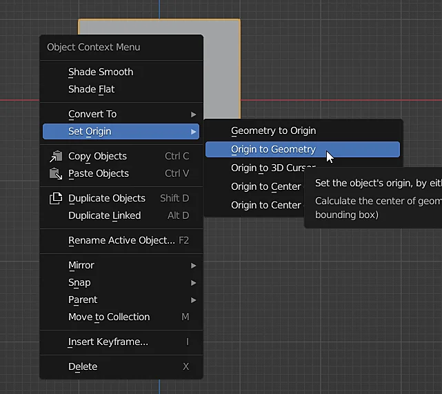
To do this we select the cube, right click on it, go to “Set Origin” and choose the option “Origin to Geometry”, as shown in figure 2. This, as the names indicate what it does is to move the origin of the object to the geometric center of it, the result in figure 3.
Fig. 2: The origin is set to the geometry of the selected object.
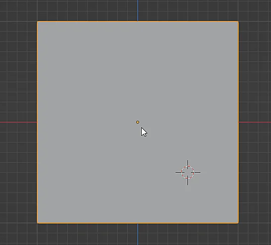
Fig. 3: The object has its origin at its geometric center and is also at the center of the scene.
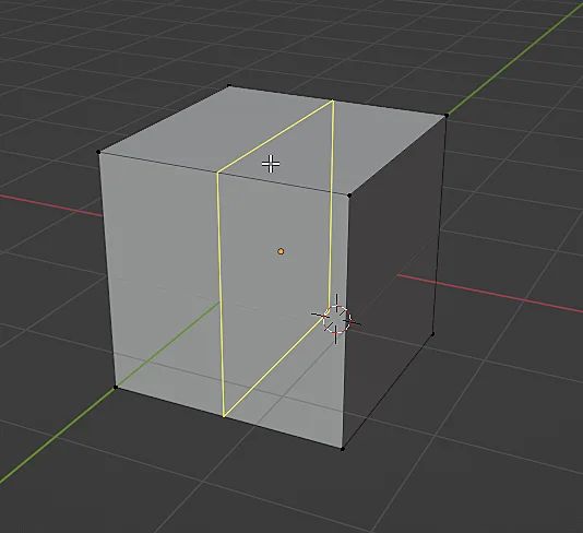
The next thing we are going to do is to make a cut in half using the command CTRL+R and bringing the mouse to the object, when the cut lines appear as shown in figure 4 we click to confirm. This adds an edge loop as shown in figure 5.
Fig. 4: A loop cut is added over the center of the cube.
Fig. 5: The cube now has a loop of vertices passing through its center.
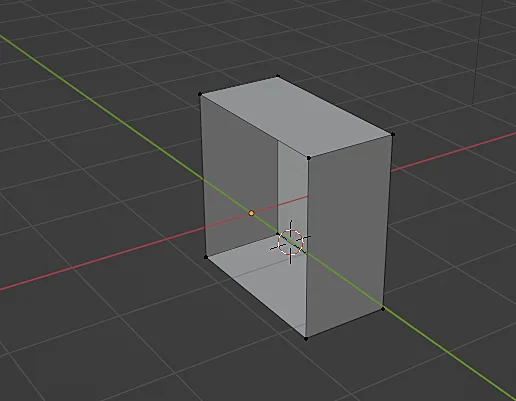
I did this to obtain a symmetrical piece with respect to the X axis and eliminate one of the halves of the cube, for this I enter Wireframe mode, select the vertices that are in one of the halves of the object (do not select the ones in the center) and with the X key we eliminate those vertices, as shown in figure 6.
With this we obtain the piece shown in figure 7 and we are ready to apply the mirror modifier.
Fig. 6: The vertices in the left half of the object are removed.
Fig. 7: We keep one half of the cube to use the mirror modifier.
How to mirror a model in Blender – Mirror Modifier
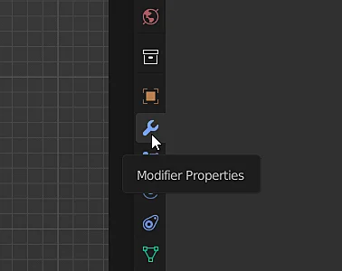
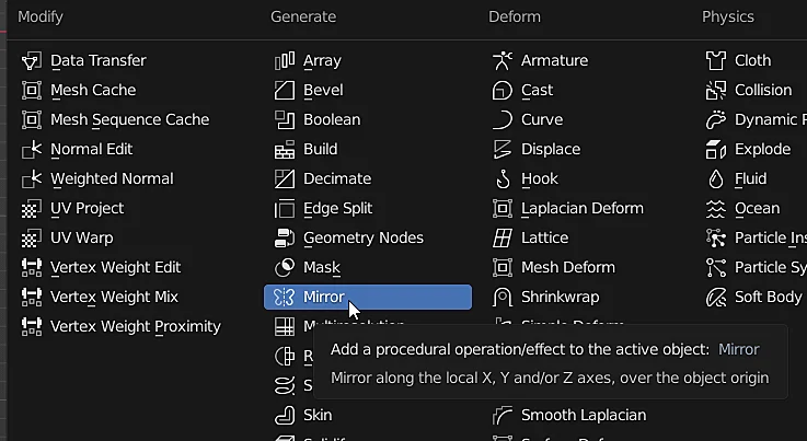
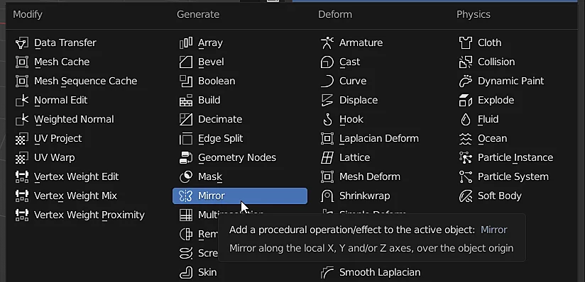
With the model we want to mirror selected we go to the modifiers tab by clicking on the icon in figure 8 and add the “Mirror” modifier (figure 9).
Fig. 8: Modifiers tab of the selected object.
Fig. 9: The mirror modifier is selected from the list of modifiers to be added.
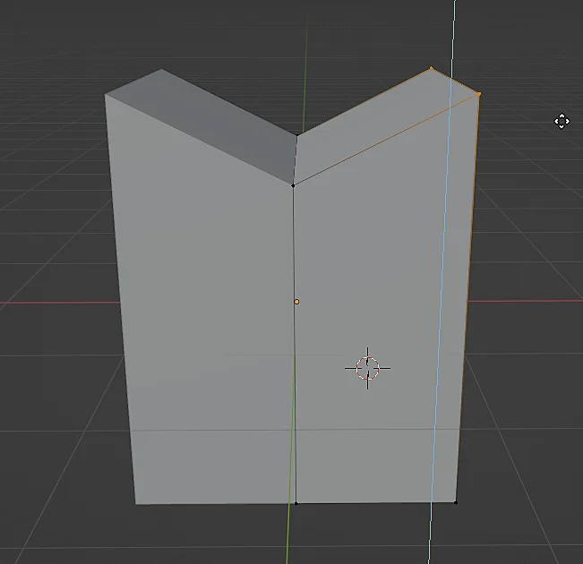
Immediately we see that the missing half appears and if we go into edit mode and modify the position of a vertex we see how the change is reflected symmetrically (see figure 10), note that in one of the halves the vertices do not appear, it means that the other half of the model is being generated procedurally.
Fig. 10: The object reflects the geometry automatically.
You can change the symmetry axis or add more symmetry axes in the modifier properties.
Fig. 11: Mirror modifier options panel in Blender.
The model going through the mirror
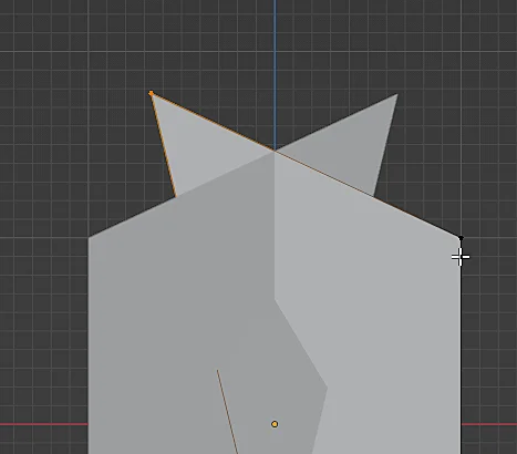
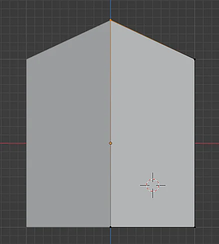
In this particular case, as we have configured it, the mirror would be like a vertical plane perpendicular to the Y axis and located at the origin of the object, which in this case coincides with the origin of the scene. Normally if we take a vertex we can make it cross the mirror plane, as shown in Figure 12.
Fig. 12: Result of the mirrored model geometry going through the mirror plane.
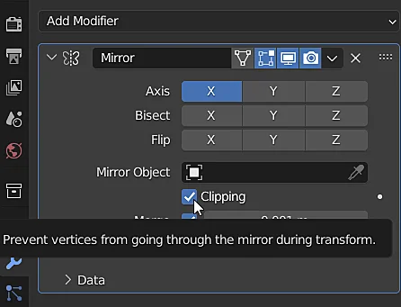
To prevent this from happening there is the “Clipping” check box shown in figure 13, when this option is activated the vertices that touch the mirror plane will remain attached to it and can only move in the two directions of the plane, in figure 14 the selected vertex is on the mirror plane and cannot move in the X axis, only in the Y and Z axis. If we need to remove a vertex from the mirror plane we can uncheck the box “Clipping” remove the vertex and then re-enable it or leave it disabled.
Fig. 13: The “Clipping” option prevents the geometry from crossing the mirror plane.
Fig. 14: Vertices that lie on the mirror plane cannot move out of that plane.
How to apply the mirror modifier
In case we need to work on the geometry of the object and add asymmetric details we will have to stop using the mirror modifier and switch to working with the complete geometry of the object. Before applying the mirror modifier it may be a good idea to save a backup copy of the model, for example by duplicating and hiding it or moving it to another collection.
Fig. 15: This object is used as the starting point for applying the mirror modifier.
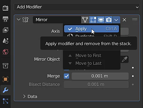
To apply the mirror modifier we click on the arrow icon to the left of the cross to remove the modifier and choose the “Apply” option, as shown in Figure 16.
Fig. 16: Option to apply a modifier in Blender.
Now the model whose geometry was being procedurally mirrored became a full 3D model with all its vertices and faces that can be repositioned without being mirrored.
Fig. 17: When applying the mirror modifier the result is a mesh with the complete geometry.
How to revert a Mirror modifier that has already been applied
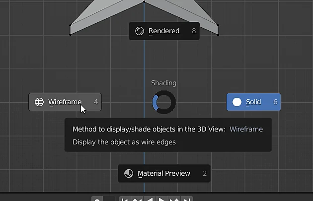
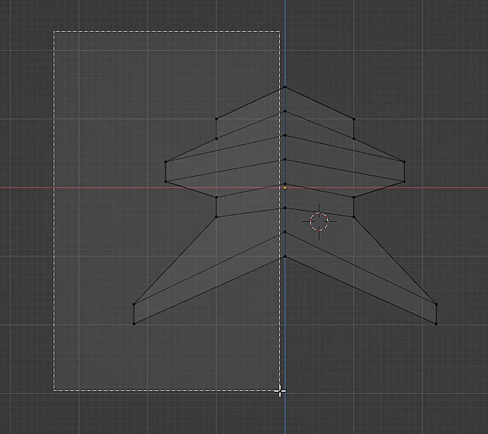
It often happens that we apply the Mirror modifier, we do several actions and then we regret it and we want to undo the changes until we have our object with the Mirror modifier applied but it turns out that we ran out of actions to undo, for this reason it was a good idea to save the backup copy of the model, However there is a very simple way to remove the vertices of the model and reapply the Mirror modifier, for that we select the model, enter the edit mode, switch to Wireframe mode (figure 18) and arrange the view in a convenient way to see the mirror plane vertically and have both parts of the model well separated.
Fig. 18: Switch to “Wireframe” mode.
Then we draw a selection box as shown in figure 19, in such a way that we select all the vertices of one of the halves of the object but without selecting the middle vertices, the result of the selection is shown in figure 20.
Fig. 19: The vertices in the left half of the model are selected.
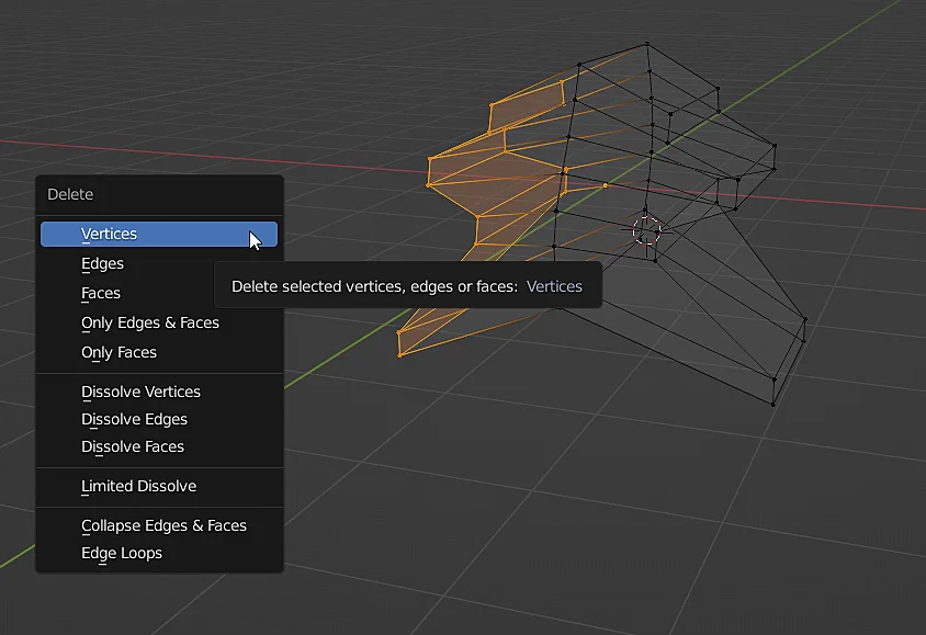
Finally we delete those vertices and we have one of the halves of our symmetrical object, ready to reapply the Mirror modifier.
Fig. 20: The selected vertices are deleted.
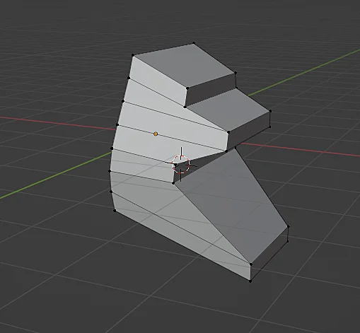
Fig. 21: One of the halves of the 3D model is obtained.
Fig. 22: The Mirror modifier is applied again.
Fig. 23: The 3D model with the Mirror modifier was recovered.
Introduction
In this article we see how to get information about the geometry of the 3D models in Blender, that is to say the vertex count, the amount of edges, faces and also the amount of triangles.
If you prefer to watch a video I have the right video for this topic:
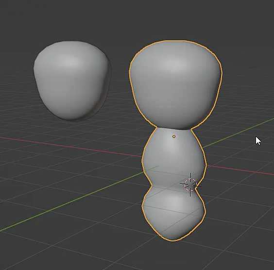
We start with a 3D model, what we are going to do is to locate the icon on which the cursor is located in figure 2, it may be necessary to change the working mode to object mode or edit mode.
Fig. 1: Starting from two objects in Blender with Shade Smooth applied.
Fig. 2: Window of the overlapping elements in Viewport.
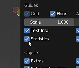
The window that appears, “Viewport Overlays”, allows us to configure the elements that are overlapped on the 3D view window, there we will click on the “Statistics” checkbox, this will show us in the upper left corner information about the models that we have in the scene and the amount of polygons.
Fig. 3: “Statistics” option that allows the display of 3D model information such as vertices, edges and faces.
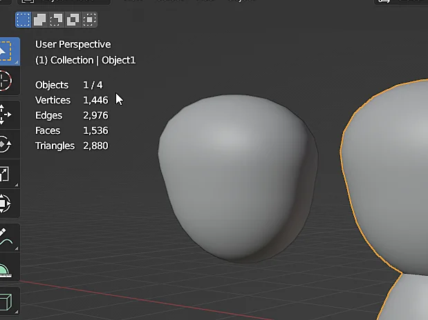
If we select an object, the number of selected objects appears next to the total number of objects, as shown in figure 4.
Fig. 4: Polygon information is displayed in the upper left corner of the Viewport.
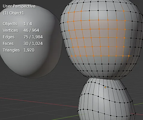
If we enter the edit mode of the selected object now the information changes and shows us the number of vertices, edges and faces of the object we are editing together with the total number of elements of that particular object.
Fig. 5: Information about the geometry of an object within the Edit Mode.
Introduction
Scale is a fundamental property of any 3D model, defining its dimensions and proportions. Ignoring scale normalization can lead to issues—from broken physics simulations to distorted UV maps. This becomes especially critical when assembling 3D environments, where consistent sizing ensures believable object relationships.
In this article, you’ll learn how to normalize scale in Blender effectively.
For a visual breakdown of this subject, you may find my video discussion helpful.
How to normalize the scale of a 3D model in blender
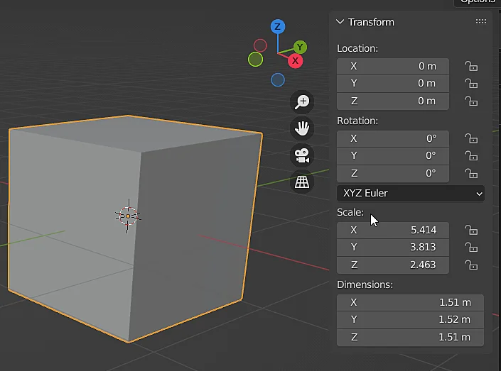
We begin with a 3D model exhibiting non-uniform scale, as shown in Figure 1. The cube’s scale values—(5.414, 3.813, 2.463)—indicate inconsistent transformations applied in Object Mode, likely from manual resizing or improper import settings.
Fig. 1: We start from a cube with a non-normalized scale.
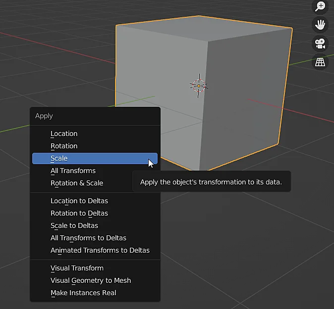
To normalize the scale of the model what we must do is to select it in the object mode and “Apply the scale“, with the shortcut CTRL+A the ” Apply” window appears as shown in figure 2, click on apply to normalize the scale.
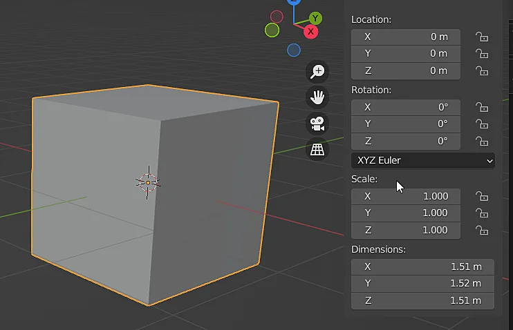
With this we are indicating that this 3D model is located in the scene in its real size. As seen in Figure 3, the scale of the model is now (1,1,1).
Fig. 2: Menu to apply different properties to an object such as position, rotation and scale.
Fig. 3: Object now has normalized scale, (1,1,1)
Introduction
In this article we see how to reuse the same material in different objects in Blender, that way when we modify the material that change is automatically applied to all the objects that are using the same instance of the material.
In the following video we see how to APPLY the SAME MATERIAL to MULTIPLE OBJECTS in Blender
Creating and assigning material to an object in Blender
The first step will be to create the material, if you have already created a material continue down to “How to reuse a material in Blender“.
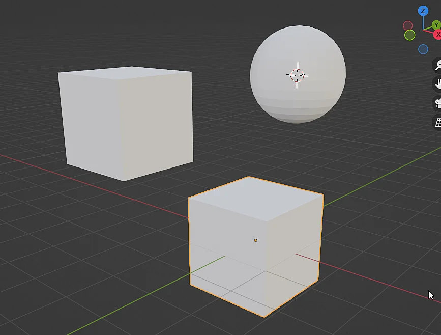
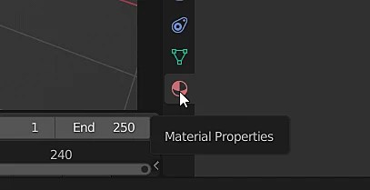
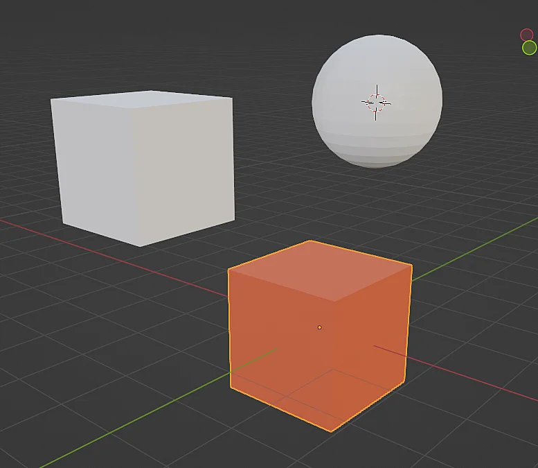
We start with the objects shown in figure 1, these have not yet been assigned any material so we will select one of them and go to the material tab with the icon shown in figure 2.
Fig. 1: Set of objects to which a material is to be applied.
Fig. 2: Material properties of the selected object.
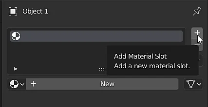
Now let’s add a new Material Slot by clicking on the + button shown in figure 3. An object can have multiple materials assigned to different faces of the model, so you can add as many slots as you need.
The next step is to create the material by clicking on the “New” button, at this point we are creating the instance of the material, this step must be done only once if we want to reuse the same material.
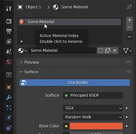
Figure 4 shows the material I have created and assigned a name and color to it.
Fig. 3: A new material slot is added to the object.
Fig. 4: This is the material to be reused in the other objects.
Fig. 5: The object shows the material that has been assigned to it.
How to reuse a material in Blender
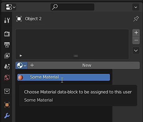
To reuse the material that was created in the previous step in another different object what we are going to do is select the other object and in the materials tab, instead of adding a new slot and creating a new material, we directly click on the materials icon (the sphere to the left of the new button in figure 6) and select from the list the material we want to reuse. In figure 7 we see the result, both objects have the same material assigned.
Fig. 6: The instance of the previously created material is assigned to the second object.
Fig. 7: Both objects show the same material.
Modificar el color en un objeto en Blender cambia el color en otros objetos
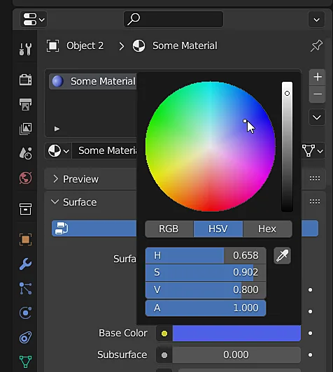
This happens because both objects are assigned exactly the same material, precisely this is the concept of instance, a material has been defined in the scene and that same material has been assigned to different objects, the objects are simply using that material, so that when we modify it, for example if we change the color as shown in figure 8, all objects that are using that instance of the material will change their appearance, as shown in figure 9. If you want each object to show a different material you will have to create new materials as shown at the beginning of this article.
Fig. 8: The color assigned to the cube material is changed.
Fig. 9: The change of material applies to all objects.
Introduction
In this article we see how to load an image in Blender to use it as a reference for the modelling process, either to exactly trace its geometry or simply to have it there and consult it to help you with the modelling. We will also see how to orient the reference image in space and how to make it transparent.
In the following video we see how to load a REFERENCE IMAGE in Blender
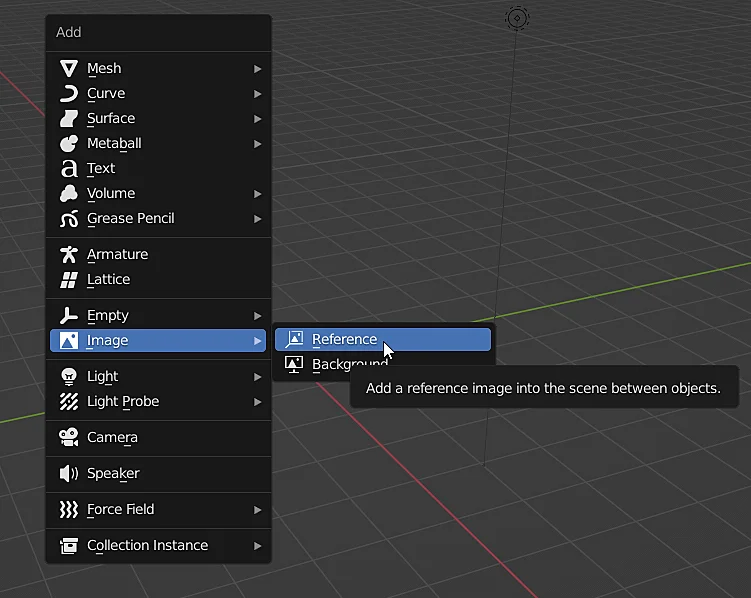
A reference image in Blender is like any other object in the scene, so to add it we can use the shortcut SHIFT+A while in OBJECT MODE, this displays the “Add” menu in a floating way, we go to the “Image” part and select “Reference”. As shown in figure 1.
A window will open in which we have to choose the reference image we need.
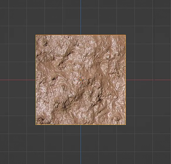
In figure 2 you can see the result of this operation, the reference image was added correctly, the problem is that it was added according to the orientation that the camera had at the moment of adding, maybe that was what you needed although in many cases one prefers to have the reference image oriented according to the front, side or top views. If that is the case you can delete the image, orient the view properly and add it again.
Fig. 1: Adding a reference image in Blender.
Fig. 2: Reference image object in Blender.
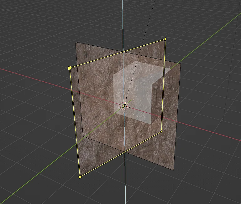
Orient the reference image in Blender
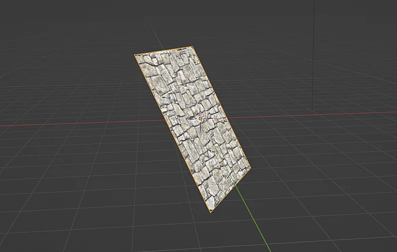
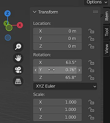
As mentioned before, the best way to orient a reference image would be to first adjust the view and then create the reference image, in this way the image already appears with the proper orientation, however, as it is an object in the scene we can also transform it, apply translation, rotation and scale. For example we can select the image, press the R key to rotate it, constrain the Z axis and type 90, so that the reference image rotates 90 degrees with respect to the Z axis. We can also type directly its orientation in the transform panel shown in figure 3. Figure 4 shows a reference image oriented according to the XZ plane (front view).
Fig. 3: Transformation of the reference image.
Fig. 4: Reference image positioned in the XZ plane.
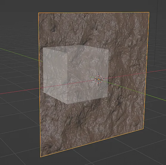
How to make a reference image transparent in Blender
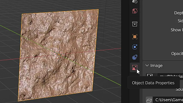
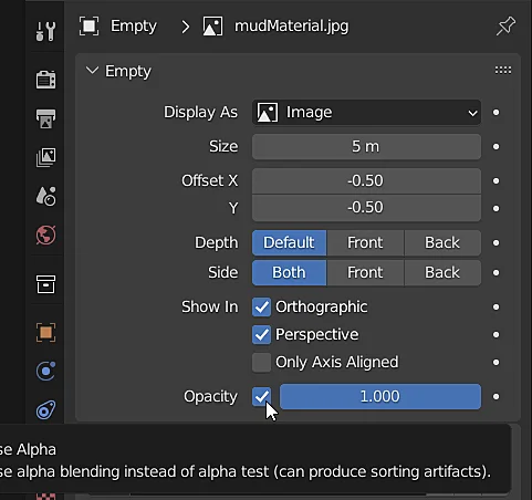
In many cases we will need the reference image to have transparency to be able to see the 3D model we are making, to achieve this we first select the image. Then we go to the image properties using the icon shown in Figure 5, note that this icon appears when an image object is selected. In the image properties we enable the opacity checkbox and set the desired value, where 1 is completely opaque and 0 completely transparent. Figure 7 shows the result.
Fig. 5: Access to the properties tab of a reference image in Blender.
Fig. 6: Properties of the reference image.
Fig. 7: Reference image with opacity in Blender.
Figure 6 shows other options to configure our reference image, for example we can make the image visible only in a certain view.
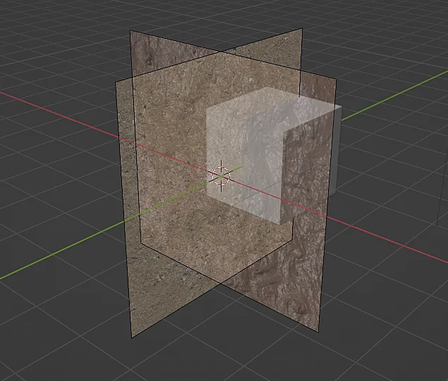
How to add multiple reference images in Blender
We can add as many reference images as we need, one way to do it is to repeat the process mentioned above, i.e. add a new image object and select the file, but we can also take the existing reference image and duplicate it with SHIFT+D, as if it were a 3D model, figure 8 shows how I duplicated an image and immediately pressed the R key to rotate it 90° around the Z axis.
Fig. 8: A reference image is duplicated from another image as if it were a 3D object.
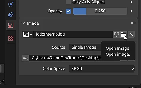
Once we have duplicated the reference image, it is now time to make the object show another image, for that we go back to the image properties tab (figure 5) and in the “Image” section we click on the “Open Image” button shown in figure 9 and load the desired image file, the result can be seen in figure 10.
Fig. 9: Modifying the reference image file.
Fig. 10: Two different reference images in Blender.
It’s your pet’s birthday and you decide to celebrate it in style by buying a huge cake, it won’t be an easy task to get it home because it’s so tall that at times it becomes a bit unstable.
How to play
Control the character with the WASD keys or the arrow keys. With the W-S keys or up and down arrow keys you avoid the obstacles in the street. With the A-D keys or left and right arrow keys you balance the cake, if the cake is falling forward press the D or right arrow key to accelerate and balance the cake again. If the cake is falling backwards press the A or left arrow key to slow down and rebalance the cake. Give the cake to your pet.
Developed for the Ludum Dare 49 Game Jam with them "Unstable" by:
MARTÍN HEINTZ
MUSIC COMPOSER
GAMEDEVTRAUM
UNITY DEVELOPER
AGUS
SOUND FX
Technical Details
Next we are going to review some information about the inner workings of this game and its mechanics, first of all it is a 3D project developed with the Unity engine.
Scene structure
This game is set up in three scenes, the first scene is the main menu which has two buttons, one to start the game and another button to close the game. By pressing the Play button we go to the game scene in which the stage and the character are set up. We go to the third and last scene when the character arrives home where his dog is waiting for him anxiously.
Character controlled by the player
The character to be controlled runs automatically with a preset speed that we can control by going forward or backward with the directional arrows or with the A-D keys, this will increase or decrease the initial speed to a certain value, the character can never go backwards, just go a little slower or faster, this movement serves mainly to balance the cake.
The character can also move to his left and right, this is achieved with the up and down directional arrows or with the W-S keys, this movement allows the character to avoid obstacles.
The unstable cake
The cake and the support tray were made in Blender and consist of separate pieces that are attached to the same skeleton, constantly playing an animation that makes the pieces of the cake jump as the character moves but also controls the angle of the bones of the cake to produce the tilt to one side or the other, The tilt of the cake responds to the character’s actions, that is, if the character accelerates the tendency of the cake is to tilt backwards, if the character goes slower the cake tends to tilt forward, in addition to this every now and then random events occur that take the cake out of its stable state and force the player to take action on it.
Music
The music for this game was composed by one of the team members. You can visit the Trepen el Paredón channel to see more of his work.
World obstacles
The main obstacles are construction fences, trees and cars, which are static elements; later on, pits are added in which, if the character falls into, the game is over. In addition, there are some cheerful workers who carry a piece of glass, these constitute a mobile obstacle.
The stage
The 3D models of the scenery are models that we made using Blender, the scenery materials have no textures, they only have applied flat colors. The character was modeled from a reference image of a low poly character that also had the position of the polygons and the topology.
In Patagonia, during the Cretaceous period there was a legendary struggle for the survival of the species, the Neuquensaurus, a noble herbivore species, had to endure constant attacks by the Overoraptors, carnivores of small stature but that, attacking in herds, are a great threat. Feed on what your environment provides, scare or step on the Overoraptors and make your offspring survive.
How to play
Move with the arrow keys, you can sprint with SHIFT and also roar with SPACE, but be careful, the Neuquensaurus will consume more energy in both cases.
Developed for the Patagonia Game Jam with theme "Dinosaurs from Patagonia" by:
MARTÍN HEINTZ
MUSIC COMPOSER
GERARDO
GAME DESIGNER
GAMEDEVTRAUM
UNITY DEVELOPER
SEBASTIÁN
GAME DESIGNER
ANDRÉS
SOUND FX
About the Patagonia Game Jam
Patagonia is a region of southern Argentina and is the region where I live, this jam was organized here and the theme was the dinosaurs in Patagonia, which had a strong presence in this region. For the event they created a discord server in which we had channels for each team and we could also talk to paleontologists to learn about the topic or ask questions and that our games have some correlation with the history of dinosaurs.
Technical Details
Next we are going to review some information about the inner workings of this game and its mechanics, first of all it is a 3D project developed with the Unity engine.
Music
The music for this game was composed by one of the members of the team, I really liked the result, especially the gameplay battle music, you can visit the “Trepen el Paredón’s” channel to see more works.
Scene Structure
This game is set up in two scenes, the first scene is the main menu that has some buttons, one to start the game, one for the credits window where you see our faces and links to our networks, we have another button to close the game and there is also a button to continue a game, but this only appears when we have already played at least once and passed the first round, which means that this information is stored in memory and then retrieve it and decide whether to show the button or not.
Dinosaur controlled by the player
The player controls the dinosaur using the directional arrows or the WASD keys, can sprint by holding down the SHIFT key and roar by pressing SPACE. The dinosaur has an associated hunger level that decreases passively but depletes faster if the dinosaur walks, even faster if it runs, and each roar costs a certain level of hunger to produce.
If the hunger bar reaches zero our dinosaur dies of starvation so we must be sure to consume the food that appears on the stage, for this just go over the bushes, also the dinosaur has an indicator that all the time points to the nearest food source.
Dinosaur egg
At the beginning of the game there is a dinosaur egg located in the nest, this egg has an associated incubation time and health level, both values are reflected in the bars in the upper left corner of the screen. The incubation time increases steadily and the health of the egg decreases if it is attacked by an enemy dinosaur. When the incubation time is up, the egg hatches and a miniature dinosaur emerges from inside.
The carnivorous dinosaurs will try to attack the egg, if we allow them to get close enough they will do some damage that will be subtracted from the health level of the egg, it can be seen in the indicator bar of the graphical interface. When the egg is completely damaged the game is over as no new dinosaurs will be born.
The egg appears again when the small dinosaur is fully developed.
Dinosaur baby
The new little dinosaur emerges when the game finishes hatching, at that moment the indicator bars change to show the dinosaur’s health and state of growth, in the hatching state the carnivorous dinosaurs will attack it in the same way as they did with the egg.
Initially I wanted to make the dinosaur hatchling have an artificial intelligence that would allow it to move around the stage independently and feed itself, for that reason there is a 3D model that looks like little colored balls, the idea was that the hatchling would look for those food sources to develop, but in the end there wasn’t enough time.
The stage
The 3D models of the scenery are models we made using Blender, the textures were made with Substance Painter.
The protagonist of the story argues with a friend, who ends up sending him to hell. Our hero takes these words very seriously and decides to fulfill this task so that his friend can forgive him. Help him in his mission to descend to the bowels of the earth without dying in the process.
How to play
Move with the WASD keys or arrow keys, you can jump with SPACE, move the camera with the MOUSE. Descend to the bottom of hell so that your friend forgives you.
Developed for the Ludum Dare 48 Game Jam with theme "Deeper and Deeper" by:
GAMEDEVTRAUM
UNITY DEVELOPER
NORBERT
VOICE ACTOR
Technical Details
Next we are going to review some information about the inner workings of this game and its mechanics, first of all it is a 3D project developed with the Unity engine.
Scene structure
This game is set up in two scenes, the first scene is the main menu scene that has only two buttons, one to play and another button to close the game. Pressing the play button starts a sequence of images and sounds narrating the story, this sequence is implemented in the same scene of the main menu and can be skipped by pressing space, when the sequence ends or is skipped, at that moment the change to the game scene occurs.
Player-controlled character
The player controls the character using the directional arrows or the WASD keys, the camera is controlled with the mouse. The first-person control was programmed from scratch before the game jam, I was doing experiments with platforms and so that a character can take fall damage, plus make that the jump has some momentum.
3D models of the city and the pit to hell
The 3D models of the scenery are models I made using Blender, some textures were made with Substance Painter while others like the textures of the buildings were taken from the browser.
A character floating in the cosmos attached to a heart and trapped in an infinite loop of rings closing over him.
How to play
Move by clicking on the screen to avoid the rings as much as you can. The click and drag mechanic is not implemented.
Developed for the Ludum Dare 47 Game Jam with theme "Stuck in a Loop" by:
ÁLVARO
PIXEL ART
GAMEDEVTRAUM
UNITY DEVELOPER
CHEMA
GAME DESIGN
About the development of this game
On October 2, 2020 the Ludum Dare 47 game jam was held, an event where you have to make a game in 72 hours based on a theme chosen by the community. The theme of the jam was “Stuck in a loop“. We participated in a team of three.
Most of the event I was live streaming what I was doing on my computer and also the discussions we were having to reach an agreement. I transmitted a total of approximately 32 hours and in the following video you can see all those hours of work summarized in 5 minutes.
40 hours of live streaming summarized in minutes
Brainstorming
A few days before the jam starts we met to propose ideas based on the candidate themes, there were three rounds of voting with 16 themes each, we took the first round and chose 4 themes at random. Then everyone took 5 minutes to think of an idea with a simple mechanic. Coincidentally the theme “Stuck in a loop” was among our chosen ones so for the jam we already had a previous idea.
Art
The general aesthetics of the game is based on the Synthwave style, with saturated colors and fonts according to that style.
The sprites are made in Pixel Art style using Aseprite software.
Technical Details
This game is a 2D project developed with the Unity engine.
Scene structure
This game is set up in two scenes, the first scene is the main menu that has some buttons, one to start the game, one for the credits window where you see our faces and links to our networks, we have another button to close the game and there is also a button to continue a game, but this only appears when we have already played at least once and passed the first round, which means that this information is stored in memory and then retrieve it and decide whether to show the button or not.
Mechanics
The character is controlled by clicking on the place on the screen where the player wants to move. The character starts to accelerate in that direction until it reaches a maximum speed and then starts to stop, this makes that for each pulse the character moves a predictable distance.
During the game there are concentric rings that are generated, each one with twice the scale of the previous one, there are different types of rings that have one or more outputs. While a ring is active it will shrink in size until it becomes tiny. The character must move to escape through the openings because, if touched by a ring, the character dies.
This is the first game to which I implemented a translation system which has a record of each text that appears on the screen and arrays containing the translations for each one, by pressing the language change button we go to the next language of the system and the system is responsible for updating each of the texts on the screen.
The game is set up in two scenes, the first scene is the initial scene of the main menu in which you can also see the credits screen. By pressing the “Play” button we switch to the game scene. Since in the game scene we have on-screen texts, it was necessary to think of a system to transfer data between scenes in order to assign the text in the appropriate language.
In the Android and Windows versions the sun sprite that appears in the background of the game scene changes size depending on the amplitude of the music, this is done by reading a chunk of the bytes from the audio clip and averaging them to get a value that will then be related to the scale of the sprite. It is not possible to do this in WebGL because one of the functions that allows us to analyze the audio clip cannot be used in WebGL. An alternative could be to pre-calculate these values for each song and to have these data organized in lists to be applied to the sprite scale.
In this game, data is saved using PlayerPrefs to remember what the maximum score was and update it if it is exceeded.
This website uses cookies to improve your experience. We'll assume you're ok with this, but you can opt-out if you wish. Cookie settingsACCEPT
Privacy & Cookies Policy
Privacy Overview
This website uses cookies to improve your experience while you navigate through the website. Out of these cookies, the cookies that are categorized as necessary are stored on your browser as they are as essential for the working of basic functionalities of the website. We also use third-party cookies that help us analyze and understand how you use this website. These cookies will be stored in your browser only with your consent. You also have the option to opt-out of these cookies. But opting out of some of these cookies may have an effect on your browsing experience.
Necessary cookies are absolutely essential for the website to function properly. This category only includes cookies that ensures basic functionalities and security features of the website. These cookies do not store any personal information.