Introduction
In this article we are going to see how to connect animation bones to a 3D model so that they can deform the model, this is useful to create poses and animations using keyframes.
PREVIOUS ARTICLE: HOW TO CREATE THE ARMATURE THAT WE ARE GOING TO USE
Starting point – We already have an armature
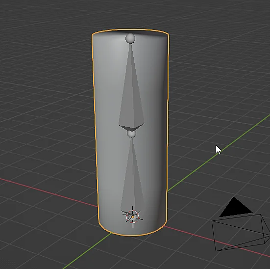
We start with a 3D model and the Armature object we want to connect to the model, you can check the previous article on how to create animation bones.


Parent 3D model to animation bones
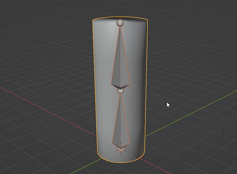
What we have to do now is to link the 3D model to the Armature object, this is done by parenting them, it is important to parent the 3D model to the animation bones, that is the Armature object has to be the parent object, note that in figure 3 the objects have been selected incorrectly, in this case, the correct way to select them is as shown in figure 4, in which the active selection is the Armature object. For more details see the article on how to parent and un-parent objects in Blender.


In the window to parent the objects we select one of the options within “Armature Deform”, each one will have different effects, in this case we are going to use the basic form that would be “With Empty Groups” (figure 5) in which groups of vertices are created within the 3D model with the names of the bones.


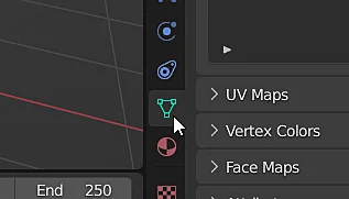
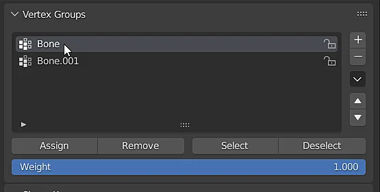
Once the 3D model is linked to the animation bones, select the object and go to the window where the vertex groups are located by clicking on the icon shown in figure 7.


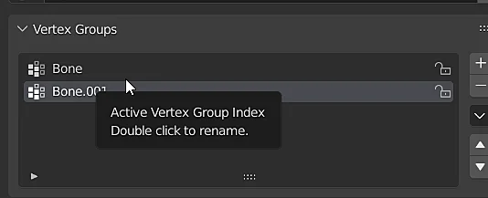
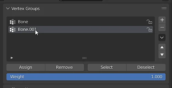
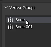
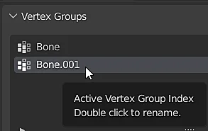
In the “Vertex Groups” section we can see the vertex groups that have been created by linking the model to the Armature with the “Empty Groups” option, at this point these vertex groups have not been assigned any vertex of the model so we are going to start assigning them.

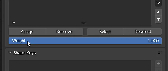
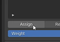
Select the model and enter the edit mode, notice in the “Vertex Groups” tab that the “Weight” field appeared, which was not there before, the Weight value allows us to indicate what percentage of influence will have a particular bone on each vertex, where the value 1 indicates total control by the bone and 0 indicates that the bone does not have any control over the vertex.


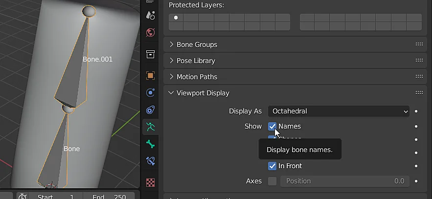
Before assigning the vertices to each group I am going to show the names of the bones, for that I select the Armature object, go to the Armature properties and in the Viewport Display window check the “Show Names” box as shown in figure 11.

Assigning vertices to bones
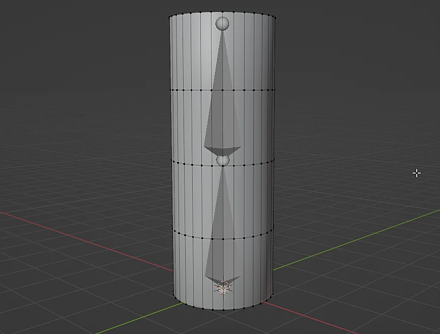
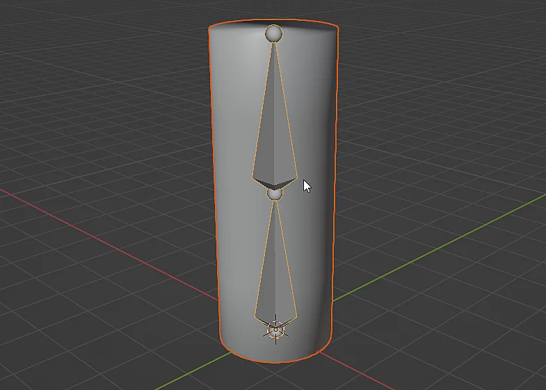
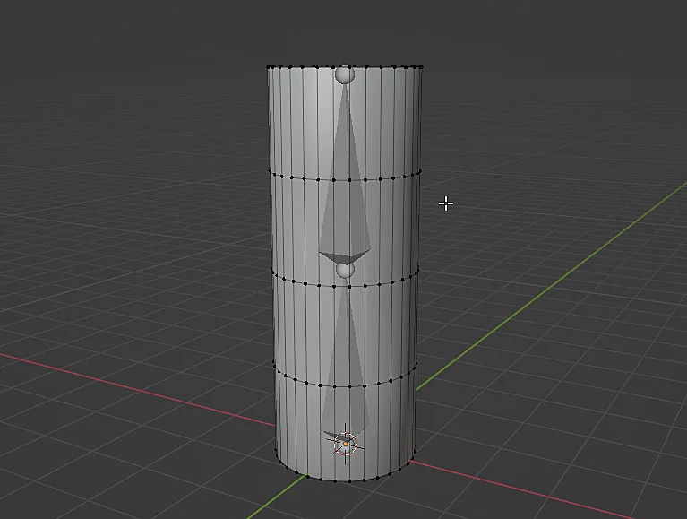
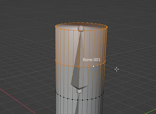
We are going to select the vertices at the top of the 3D model, those shown in Figure 12.

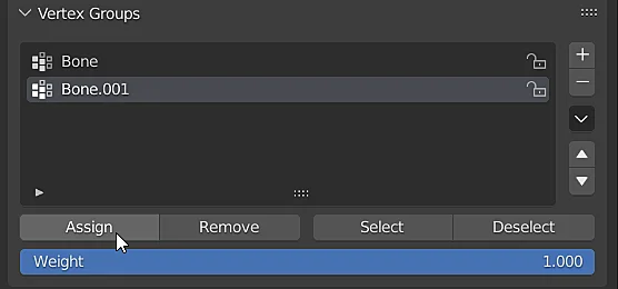
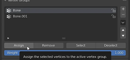
Con los vértices seleccionados vamos a la ventana “Vertex Groups” y seleccionamos el grupo al cual asignar los vértices, en este caso el grupo “Bone.001” y acto seguido pulsamos el botón “Assign” que se muestra en la figura 14.


Test if the bone deforms the assigned vertices
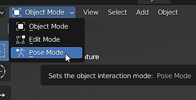
Before assigning more vertices we can do a test to see if what we did worked, for that we select the Armature object and go to pose mode, as shown in figure 16.


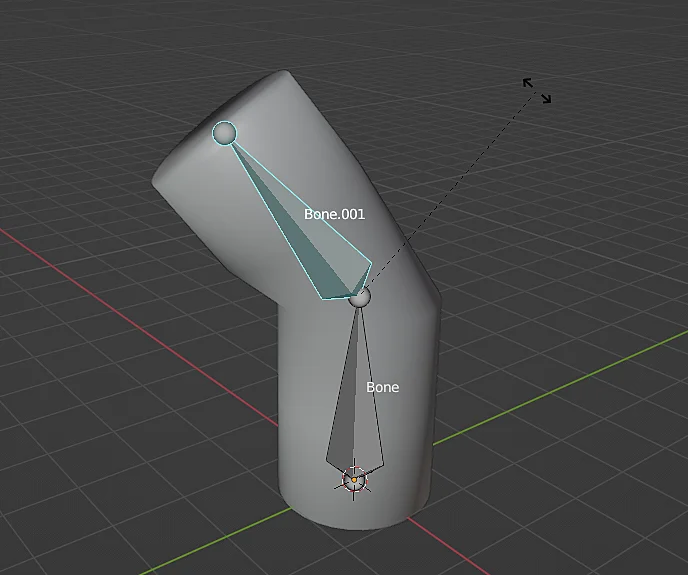
In pose mode we select the bone and rotate it, if everything went well we should see that the bone deforms the vertices that were assigned to the group, as we can see in figure 17.

Assigning the remaining vertices to the animation bones
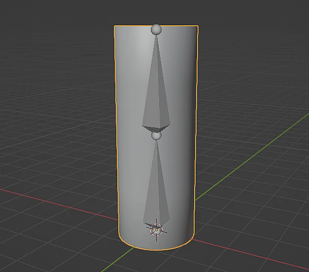
Now we are going to select the vertices of the lower part of the model which will be totally controlled by the bone at the bottom.


Vamos a la ventana “Vertex Groups”, seleccionamos el grupo correspondiente y hacemos clic en el botón asignar.


Make two animation bones control a group of vertices
For the remaining vertex loop what we are going to do is that both bones can control the vertices, for this we have to repeat the previous process but change the Weight parameter. We start by selecting the set of vertices, a quick way to select an Edge Loop is by pressing ALT and clicking on one of the edges of the loop we want to select.


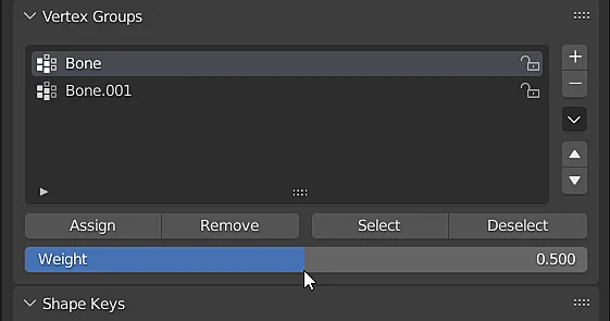
Then go to the “Vertex Groups” window and change the Weight value to 0.5.


Then we select the first group and assign the selected vertices to it.


Then we select the second group and also assign the selected vertices to that other group.

As the vertices were assigned to both groups in each of them with weight equal to 0.5 with this we have established that each bone will have a 50% influence on these vertices. In Figure 28 you can see the result of all this.


One thing that could have been done is to assign the intermediate vertices weights of 0.25-0.75 in each corresponding group.