In this article we’re going to analyze how to apply the LookAt function in Unity, to make a GameObject look in the direction of another GameObject.
Procedure
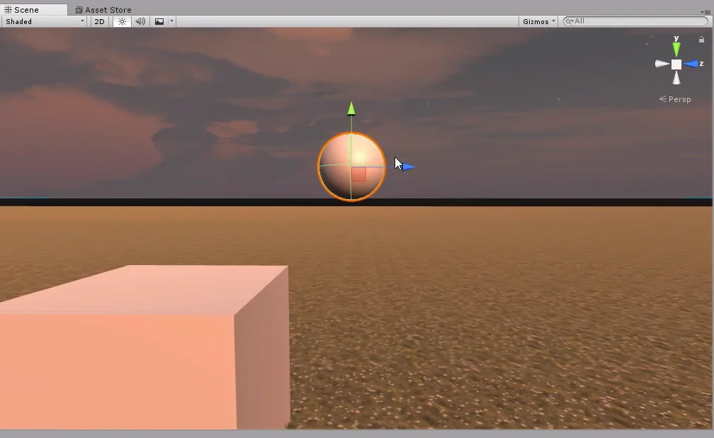
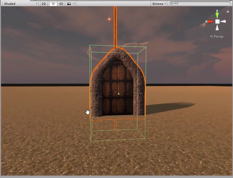
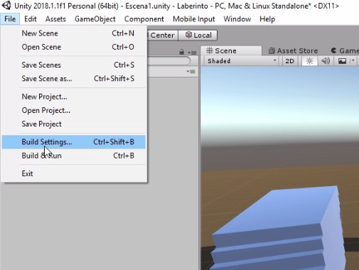
We are going to work with the Look At station, which consists of a containment capsule in which Lucy’s model is floating. The goal is to get Lucy to follow us with her gaze all over the stage.
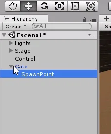
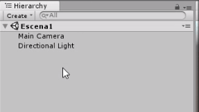
In the hierarchy we have a GameObject called “#3 LookAtObject”.
Fig. 2: Hierarchy of the scene. The LookAt station is GameObject #3.
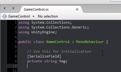
This GameObject is assigned the “LookAtObject” Script, which will see to it that Lucy follows her gaze on the player.
Fig. 3: Script to complete in this challenge.
Figure 4 shows that there are 3 fields to complete, the first is for the observer object, the second is for the observation objective and the third is for Lucy to look at a fixed height of the stage, so she does not leave the border of her capsule containment.
Fig. 4: Script assigned to the GameObject “#3 LookAtObject” shown in figure 2.
We’re going to assign Lucy directly from the hierarchy and we’re going to find the character through her tag.
If we open the script we find some things done. In the FixedUpdate method, which is executed once every so often, we make the call to the “lookAtObject” method, which will fulfill the function.
Fig. 5: Script LookAtObject sin completar.
In the start method seen in figure 5, we have an instruction that was commented at the time of making the capture. You have to remove the comment bars to find the player’s reference and get Lucy to look at it.
Fig. 6: Fields defined in the Script.
Figure 6 shows the fields defined in the Script. We are going to use the Vector3 called “objectToLookPosition” for the coordinates that Lucy must look at.
Fig. 7: With these two instructions we get Lucy to look at the origin of the character.
Within the “lookAtObject” method we write these instructions:
With these two instructions, Lucy is always oriented towards the player’s origin.
Fig. 8: Lucy sigue al personaje con la mirada.Fig. 9: When approaching the capsule, Lucy leans so far that she goes beyond the boundaries of the capsule.
The challenge is partially solved, we still have to solve the problem illustrated in figure 9.
Fig. 10: Three GameObjects showing their origins. The origin is represented by a gizmo showing the local axes.
First let’s understand what’s going on.
All GameObjects have a coordinate in the space where their origin is located.
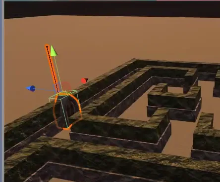
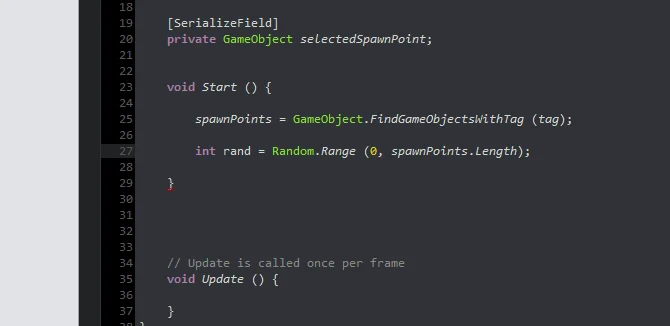
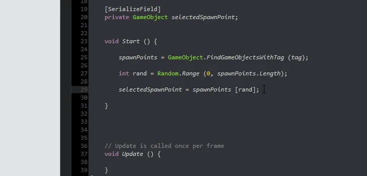
The LookAt method will modify the orientation of the object to which it is applied (in this case Lucy). It will do this in such a way that the local forward axis points to the origin of the object to look at. As illustrated in the following figure.
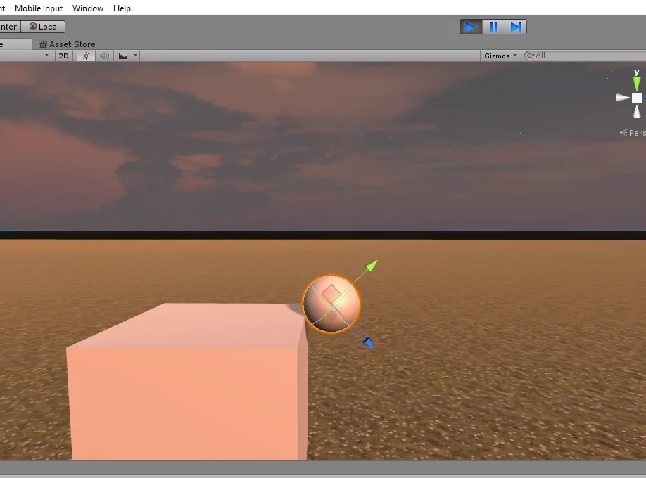
Fig. 11: Lucy with the At look method applied, character away.
If the character is far from Lucy his inclination is small, but when he gets closer the following happens:
Fig. 11: Lucy with the applied lookAt method, character in close proximity.
How can we correct this?
We need to get Lucy to look at a coordinate that’s at the same height as her origin. That way her tilt angle will be small.
So we are going to overwrite the component and of Vector3 by the value of the variable “yPos” that we will adjust from the inspector.
Ideally we could make the component and the Vector3 worth exactly the height of Lucy’s origin, this is something I realized later in the post production of the video. However it is good as an example that there is no single way to solve the problems.
Fig. 12: An instruction is added between means that overwrites the value of the component and the Vector3.
You can try writing the variable yPos at runtime, but when you stop the simulation all changed values will return to their initial value.
The value 0.75 works well for this case. A number less than this causes Lucy to lean down and come out the front of the capsule.
Fig. 13: The value -0.3 causes Lucy to exit from the front of the capsule. Fig. 14: With yPos equal to 0.75 Lucy looks correctly at the character. Fig. 15: With yPos equal to 0.75 Lucy looks correctly at the character.
In the following article we will study how to create and destroy objects at runtime. Subscribe to the YouTube channel to stay on top of new videos and articles.
Introduction
In this article we are going to explain what is a variable in programming, what types of variables there are, what they are used for and show some examples of variables in C#, in the development of video games with Unity.
What is a Variable in programming?
Variables are used in many disciplines, perhaps the most common example is the “X” variable in mathematics, which is generally an unknown value that we must find. In programming, variables are a somewhat different concept.
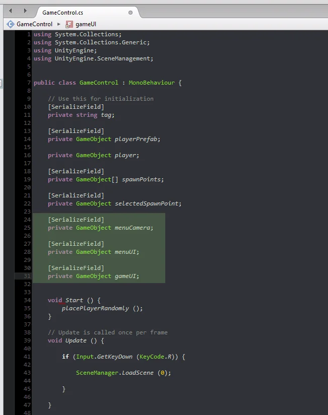
To understand the essence of computer variables we need to know a little about computer memories.
Computer memories store information in the form of bit registers (i.e. sets of values that can be 0 or 1). This information will be interpreted and used by the computer programs. Computer memories contain many of these registers, so each register has an address that allows it to be found, read and written.
Then we can say that a variable is a piece ofinformation stored in the memory of the computer. The identification name that we assign is associated with the address within the memory and the value we save is the information contained in the variable.
Examples of variables in programming
The variables can be of different types, depending on the information we need to store. In figure 1 we see different types of variables and their assigned value.
Fig. 1: Examples of variables, identification name and value.
The variable “age” contains the value 22, this means that when we use the word “age” in our program, indirectly we will be using the value 22.
If we do the operation “2*age” (2 multiplied by age) it will have a result of 44.
Fig. 2: Examples of variables with poorly chosen names.
Choosing Names for Variables
Figure 2 shows variables that have been defined with confusing names. This happens very often when we want to solve things fast. It is important to choose representative names of the variables, because after a while we forget what we did and when we have to make changes it is difficult to understand.
The variable “house” in figure 2 has the value “false”. This variable could have been used, for example, to know if a character is in his house and if it is true to restore his health.
When putting a context it makes sense that “house” is false, this means that the character is not at home. However, it may take us a while to figure out what the function of the variable was.
We can save the effort by simply defining the variable as for example “characterAtHome”. Now the name of the variable suggest us its function.
Types of Variables in Programming
Let’s know the most basic variables that we are going to use to solve our problems. The examples are taken from the Labyrinth Game Series (click on the link to go to the main page of the series).
Variables type Boolean (bool)
The bool variables are named after the Boole Algebra developed by mathematician George Boole. They can be found in 2 possible states: True or False. We use them to solve logical operations.
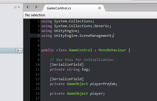
Fig. 3: Fragment of the “GameControl” script from the My First Game on Unity project.
In the method seen in figure 3, we define the bool “validSelection” and initialize it with the false value.
Inside the while loop you select a random piece from the labyrinth and check if it is far enough from the character.
If the labyrinth piece is very close to the character, validSelection remains false and the program chooses another labyrinth piece again.
If the labyrinth piece is far enough away, validSelection will become true and the program will go ahead using that piece.
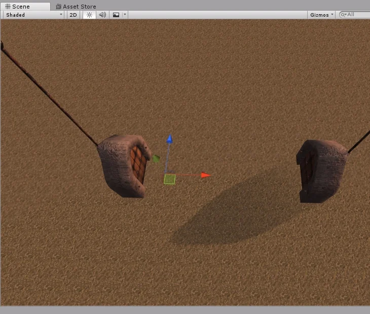
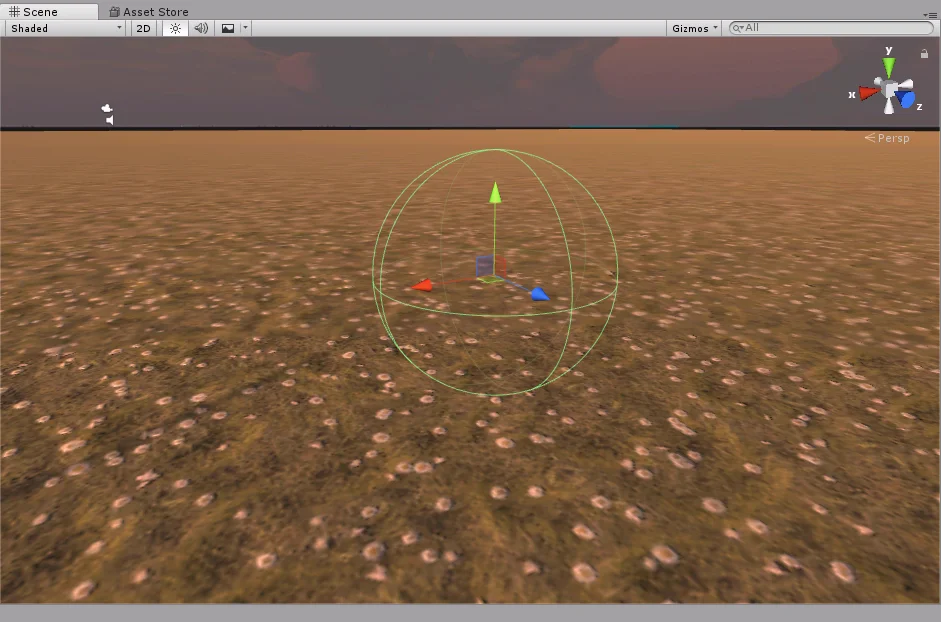
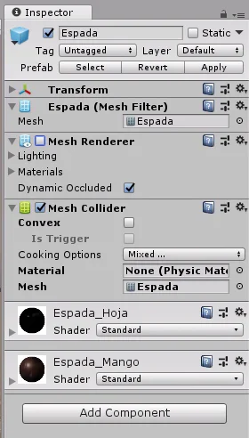
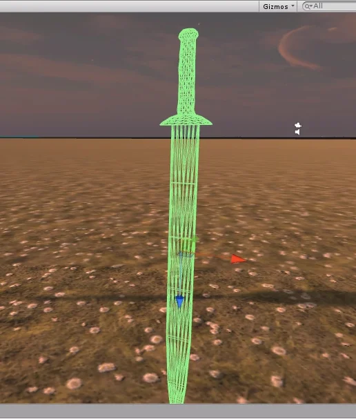
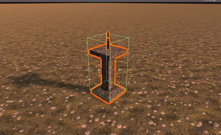
Fig. 4: The object to be found in the labyrinth is a pedestal with a sword.
Integer type variables (int)
The “int” type variables do not serve to store positive and negative integer values.
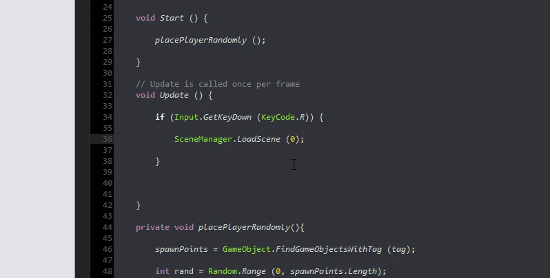
Fig. 5: Fragment of the “GameControl” script from the My First Game on Unity project.
In the method shown in figure 4, you see several integers, “nPieces”, “labyrinthPieces.Length”, “nClocks”, the numbers 0 and 1 and the iteration variable “i”.
Let’s take the case of the iterator variable “i”, it is declared and initialized with value 0 inside the for loop and it is used to execute the “placeAClock” method as many times as the value of nClocks is.
For example if we want to have 10 clocks in the scenario, we make “nClocks” worth 10, then the for loop will execute 10 times the “placeAClock” method.
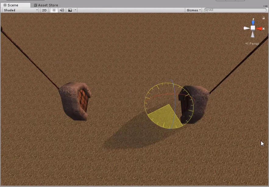
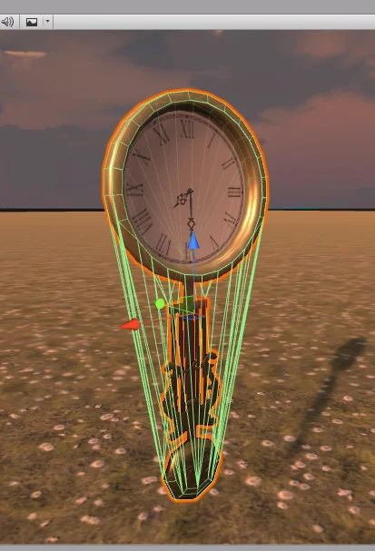
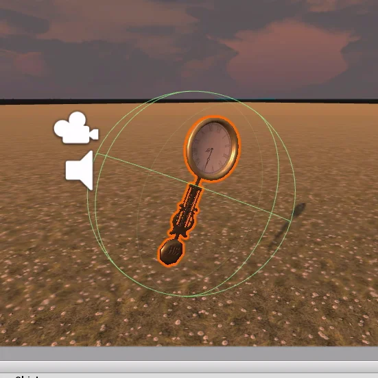
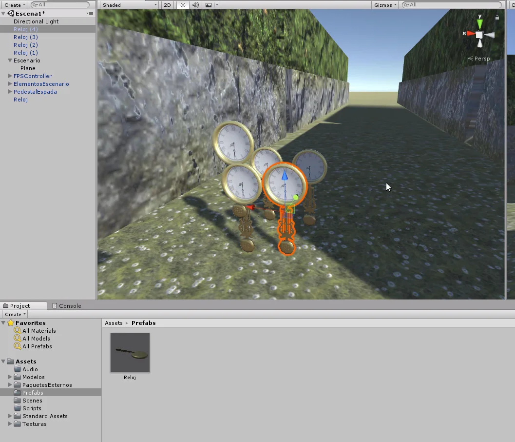
Fig. 6: Watches that appear in the maze and give the player extra time.
Float Variables
Floating point variables are used to represent real numbers. That is to say, besides positive and negative integers we can represent numbers with decimal part. This type of variables can serve us for example to represent physical magnitudes.
Fig. 7: Fragment of the “Lucy” script from the project My First Game at Unity.
In the video of the Halloween 2018 special we defined a script for the NPC Lucy, a ghost that dwells in the labyrinth. Lucy chases the character with some speed.
To solve this behavior we make a linear interpolation between the position of the character and Lucy’s position using as parameter the float “velocity” multiplied by the float “Time.deltaTime”.
Fig. 8: Lucy chasing the character.
String Variables
Strings are not a variable in itself, but instances of a class, however many development environments allow us to treat strings as primitive variables.
We use them to store text.
Fig. 9: Fragment of the script “UIManager” from the project My first game at Unity.
The “showMessage” method seen in figure 9 belongs to the script “UIManager”, this method receives as a parameter a string called “message” and is responsible for displaying it in the user interface, as illustrated in figure 10.
Fig. 10: Example of a message displayed when interacting with certain objects.
Conclusion
In this article we saw what a variable is in programming and how we can use it to represent different types of data.
A variable in programming is a reference to a space in the memory in which a data is stored. We can assign it the name we want and when using that name we will be referring to that data stored in that particular part of the memory.
IMPORTANT UPDATE
This article is part of an older video series,a NEW SERIES is now available that goes into more depth on the topic of finding any GameObject or Components from a Script.
The following video is the introduction of the series on how to FIND GameObjects and components from a script in Unity
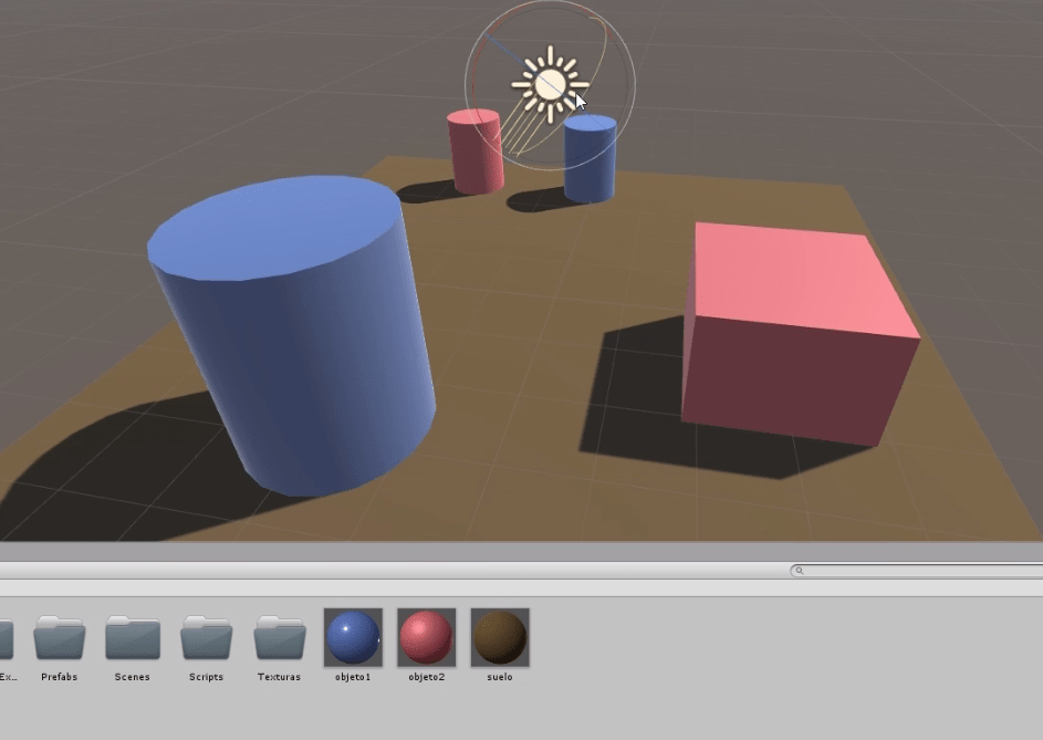
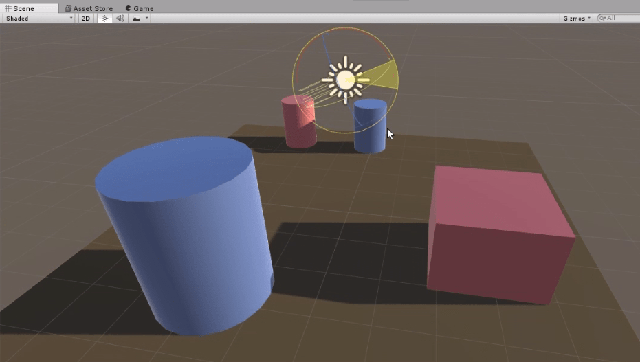
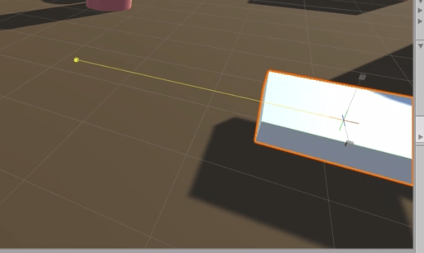
Let’s work with the Find GameObjects station, which consists of 5 objects on a table. The function of this station is to return objects that are disturbed to the resting state.
The problem is that initially we don’t have the object references, so the function can’t be carried out.
Fig. 1: 5 modelos 3d similares a trofeos en una mesaFig. 2: Station for finding disturbed objects. After a few seconds the objects disappear.Fig. 3: Station to find objects returning to the resting state. After a few seconds the objects reappear in their initial position.
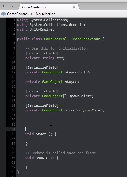
Inside the “FindGameObject” Script we have some code already written.
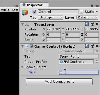
Fig. 4: FindGameObject script. Definition of the objects to be found.
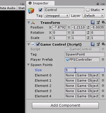
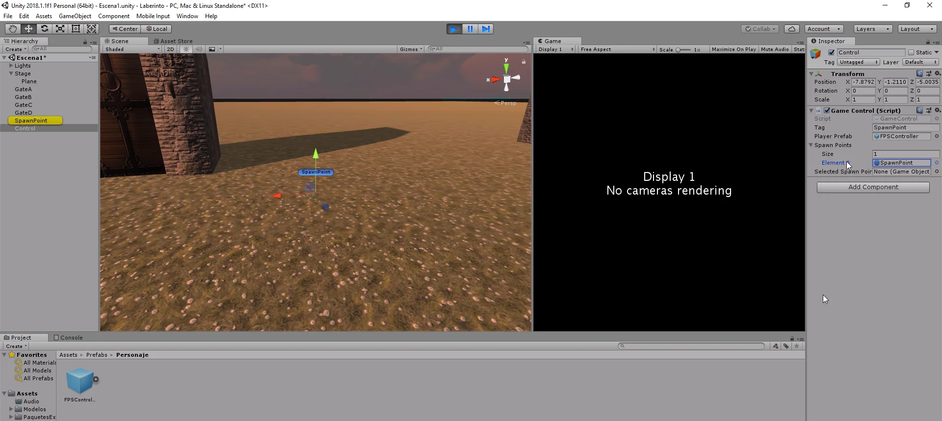
The 5 objects are declared as private and are serialized, so they appear in the inspector (as shown in the following figure).
Fig. 5: Fields in the inspector for the references of the GameObjects.
In the Start method there is a call to 5 methods that will find the references.
Fig. 6: Call to the methods in charge of finding the object references.
The methods are incomplete. Our goal is to complete them and discover different ways to find the references.
Fig. 7: Methods for finding object references.
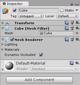
Way #1: Assign objects directly in the inspector to a serialized field.
As you can see in figure 4, all objects are defined as private and serialized, but this is more than anything for us to see in the inspector, how to start the game we find the reference.
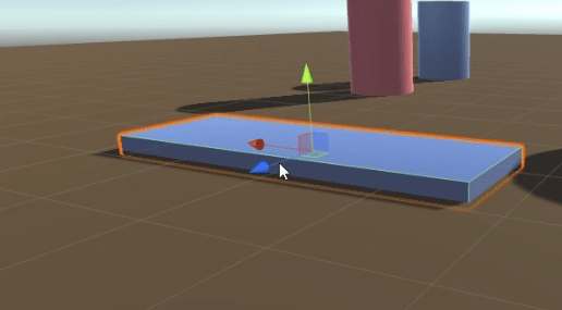
For the 1st way, we take the object from the hierarchy and drag it into the field in the inspector. As illustrated below.
Fig. 8: Assignment of GameObject to field in the hierarchy.
With this we already tell our Script which object of the hierarchy is the GameObject defined with the name “Object1a”.
Way #2: Assign objects directly in the inspector to a public field.
This form is practically the same as the previous one, only now GameObject is defined as public.
Fig. 9: Definition of a GameObject with public visibility.
Defining a field as public makes it accessible from any context and therefore also appears in the inspector.
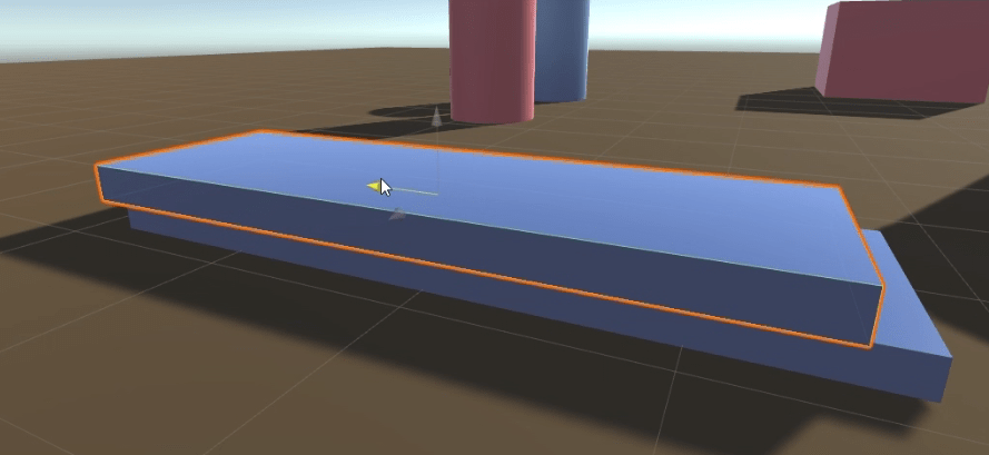
As in the previous form, we take the GameObject from the hierarchy and drag it into the field in the inspector.
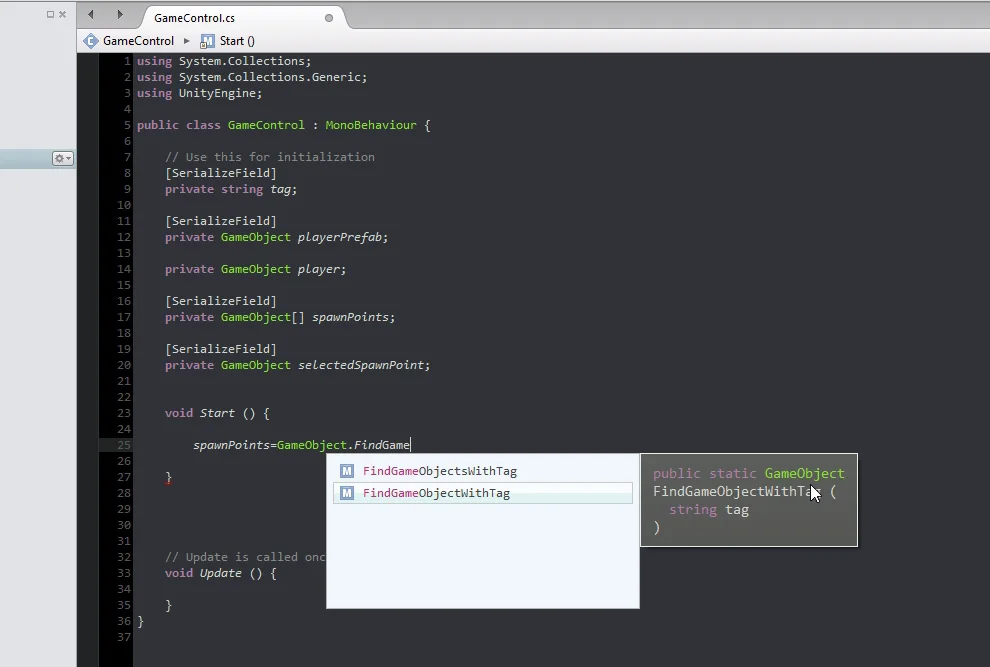
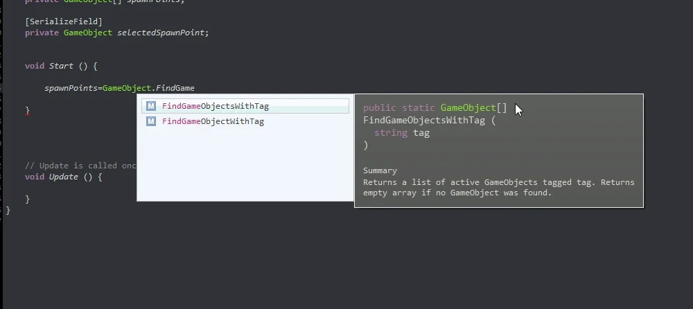
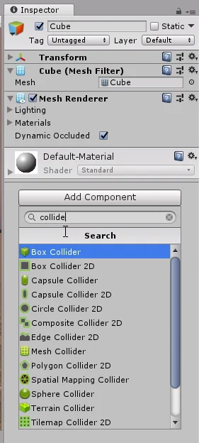
Way #3: Labels. FindGameObjectWithTag method of the GameObject class.
The GameObject class has a method that allows you to find a GameObject in the hierarchy using the tags.
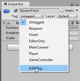
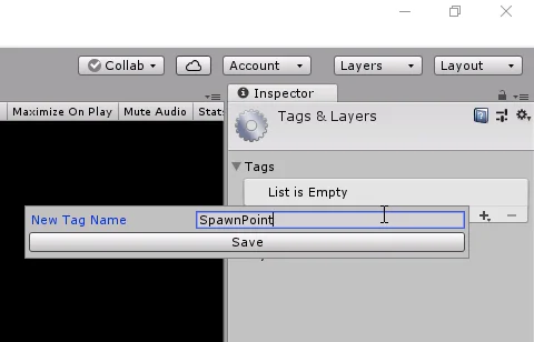
Fig. 10: Tag drop-down menu present in all GameObject in the hierarchy.Fig. 11: Window that appears when you click on “Add Tag” (figure 10) and then on the “+” sign.
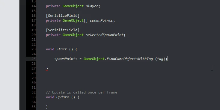
Then we proceed to write the code necessary to find the GameObject from the Script. We are going to write it inside the method “findGameObject2” that is seen in figure 7.
We are going to analyze it in parts, when writing “object2=” we are saying that the field object2 is going to be worth whatever we place after the sign “=”. As can be seen in figure 9, object2 is of the GameObject type, so what we place after the sign “=” will have to return an object of the GameObject type.
By typing “GameObject.” (GameObject dot), we are indicating that we want to access the attributes and methods that are defined in the GameObject class.
We run a method called FindGameObjectWithTag” (translated means: “find GameObject with tag”), this method needs that we enter (within parentheses) the String with the tag.
Reading this and interpreting it is complicated, but little by little it makes sense as we learn.
In the video we can see that when running the game, we managed to find the object2 reference.
In the C# language, capital and small letters are distinguished, so they must be respected.
Way #4: Name. Find method of the GameObject class.
As you can see in figure 10 above the Tag dropdown menu, there is a space with the text “Object2”, this is the name assigned to the GameObject and with that name is listed in the hierarchy.
Using the Find method of the GameObject class we can find a GameObject by name, as follows:
object3=GameObject.Find(“Object3”);
With this instruction, Unity will review the hierarchy, find the object named “Object3” (if there is one) and assign it to the object3 field.
If there is no GameObject named “Object3” in the hierarchy, the object3 field will have the value null. If there is more than one object that has the same name, we can’t be sure we’re going to find the one we want.
Way #5: Single component. Method FindObjectOfType.
The last way we’re going to see is a little more complicated.
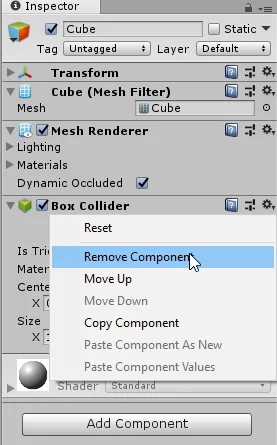
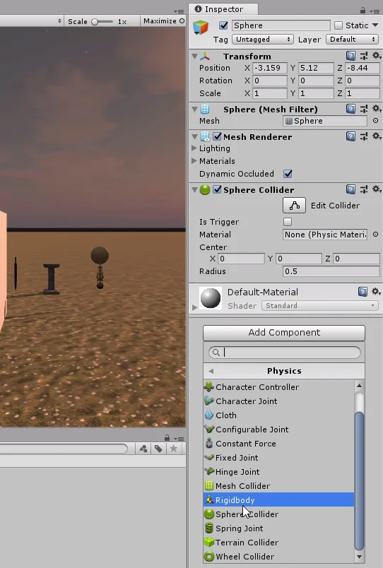
The GameObject class allows us to find the reference to a component that is present in the hierarchy, for example the Transform component, Collider, RigidBody, etc.
Of course, practically all GameObjects have the Transform component, so in principle it wouldn’t be very useful. But what if the component we’re interested in is unique in the hierarchy? In other words, we know that there’s only one GameObject in the hierarchy that has it. This might help us, because finding that single component is equivalent to finding that GameObject.
It could be any component as long as it is unique, in this case we create a new Script with the name: “Object4Script” and we assign it to the GameObject of the hierarchy called “Object4”.
Then we write the following code in the “findGameObject4” method (see figure 7).
First we find the Object4Script type object reference with the FindObjectOfType method of the GameObject class, then we access its transform component through the dot operator and then the gameObject component. The result of this is assigned to object4.
In this way we can find the GameObject from one of its components. Of course, if there is another GameObject that also has that component, we might find the wrong GameObject.
Introduction
In this article we are going to see several methods from the Input class that will alloud us to read keyboard and mouse inputs in Unity.
Before we begin, I invite you to watch the following video that resolves this problem, make sure to activate the english subtitles.
Procedure
In the first video we are going to work on the input station, which consists of models for the “WASD” keys and mouse buttons.
The goal is to get them to change color when the corresponding entry is pressed.
Fig. 1: GameDevLab input station.
En la jerarquía hay un GameObject llamado #1 Input. Este objeto tiene todos los elementos relacionados a la estación de entradas.
Fig. 2: Hierarchy. The input station is the GameObject called #1 Input.
This GameObject is assigned the Read Input script, which will be responsible for reading the entries and performing actions on the elements of the station.
Fig. 3: Script Read Input assigned to GameObject #1 Input.
There’s no need to do anything in the hierarchy. Go to the folder “Scripts to Complete”, “Video 1 – Read Inputs” and open the script “ReadInput”.
Fig. 4: Script Read Input not completed. The missing code goes into the Update method.
Why should the code go in the Update method?
All scripts that extend their MonoBehaviour class behavior have an implicit Update method, which is automatically evaluated in each frame of our game.
As explained in the video, if our game runs at constant 60 fps, the Update method runs 60 times per second.
The reading of the Inputs is a random event, so we cannot determine when the player will press a button. For this reason, when we need to read the entries, we must do so in all frames.
How do we read the inputs?
Let us imagine that we can ask the computer in colloquial language about the state of the entries, what questions would we ask?
Fig. 5: Questions to ask.
If the answer to these questions is yes, we will execute an appropriate action for each one.
We already have the idea, now we just have to ask these questions using a language that the computer understands.
Using the if sentence, we can ask questions whose answer is true or false.
Unity’s Input class handles the inputs, so we use their methods to solve the problem. We have the GetKey method for the keys and GetMouseButton for the mouse buttons, in the argument of these methods we indicate the key using the enum KeyCode and the mouse button using integers, as can be seen in figure 6.
Solution
Fig. 6: The missing code is complete.
In this way, we can ensure that the Input station fulfils its function.
Fig. 7: Input station. W key pressed. Fig. 8: Input station. Key A pressed. Fig. 9: Input station. Click left.Fig. 10: Input station. Right click.
Conclusion
As a first conclusion, I would like to mention how we went from thinking about the problem in colloquial language (figure 5) to writing it in C# language (figure 6). Thinking about the problems in this way is simpler, because we abstract ourselves from the programming language.
An intermediate step between this colloquial language and the C# code would be the pseudocode.
Reading Inputs is the way we know what the player wants to do, so we have to define what tickets we are going to offer and when we want to read them (for example perhaps we are not interested in reading the WASD tickets when we show a cinematic).
Input events are random, that’s why we must read them continuously using the Update method.
To avoid complications it is advisable to read the inputs in a single script.
There may be other types of inputs, such as a JoyStick or tactile entry. We must study Unity’s Input class to understand how to handle them.
Introduction
A vector is a mathematical tool that allows us to represent magnitudes in which not only the intensity (or modulus), but also the direction and direction in which they are applied are important.
The vectors are very useful in the development of games, they allow us to define directions for movement, do ray tracing, among other applications.
The simplest and perhaps the most everyday example I can think of is that of a force. Forces are vector magnitudes, not only does the amount of force applied matter, but also direction and meaning.
If, for example, we change the direction of the force we apply to an object, the object will probably move in the opposite direction.
Other examples of vector magnitudes can be torque, angular momentum, velocity. In electricity and magenithm we have the electric field at one point, the Poynting Vector.
Vectors in the plane and in space
For practical reasons we are going to look at the case of vectors in the plane and in space, i.e. vectors of two and three components respectively.
Mathematically
Usually a vector is identified by a letter with an arrow at the top.
There are different types of notations, one of them is to write the components of the vector in parentheses and separated with comma. In the plane we use two components and in the space three.
Fig. 1: Examples of vectors in the plane and in space.
Graphic Representation
The value of the vector represents the final point of an arrow starting from the origin of coordinates (i.e. (0.0) in the plane and (0.0.0) in space), to the coordinate indicated by the vector. As illustrated in figure 2.
Fig. 2: Graphic representation of vectors in the plane (left) and vectors in space (right).
Characteristics of a vector
Components
The components are the actual values for each axis of the coordinate system.
In the plane a vector has two components, generally x and y, in space we need three components, in general they are called x, y and z.
Magnitude
The module, norm or magnitude of a vector tells us about the size of the vector, the magnitude or intensity it has, in other words is how much the vector measures from the origin to the final point.
To calculate the module, Pitagoras’ theorem is used on the right triangles formed by the vector with the coordinate axes. This sounds somewhat complicated but the formulas are simple, in figure 3 we see the calculation of the norm of a vector in the plane and in space. Formula with examples.
Fig. 3: Calculation of the module or norm of a vector in the plane and in space.
Orientation
The orientation of the vector in the plane or in space. This allows us to calculate angles with respect to coordinate axes using right triangles, sinuses and cosines.
Given a vector we can find a single line that contains it.
Here we begin to see the usefulness of knowing about vectors to program video games, with the vectors we can represent movements in a determined direction or calculate the trajectory of a projectile for example.
Sense
Given a direction for the vector, we said that there is only one line that contains it, however the vector could be pointing to one side or the other of the line. With meaning we solve this ambiguity.
To change the direction of a vector it is enough to multiply by -1 all its components.
Vector in mathematics vs Vector in programming
In programming there is also a type of data known as vectors, arrays or arrays. However, this refers to a programming structure in which we can order data of the same type and use them to solve algorithms.
We can model mathematical vectors using arrays, however arrays can contain strings of text for example.
Mathematical Vectors in Unity
In Unity there are several components that use vectors, the simplest of which is the Transform component that determines the position, rotation and scale of a GameObject in Unity.
For this it uses three three-dimensional vectors. In figure 4 we can see these vectors in the inspector. Unity gives the vector components the name x, y and z.
Fig. 4: Transform component that has all GameObject in Unity.
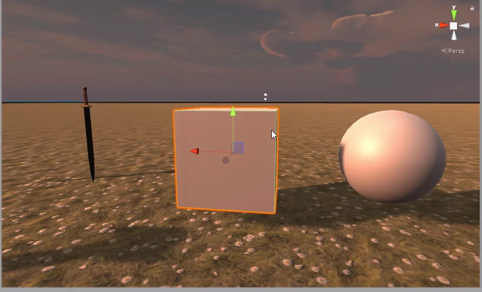
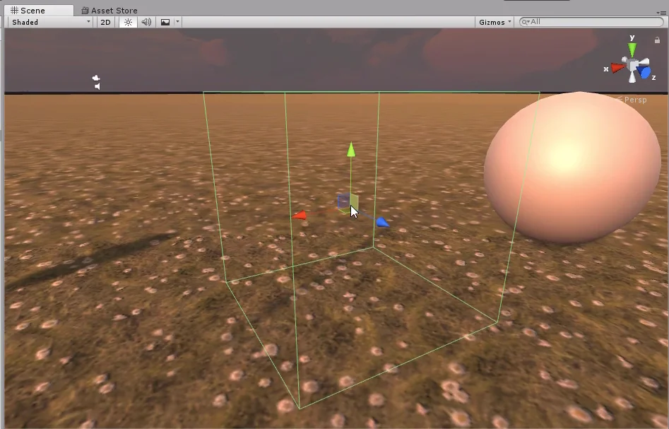
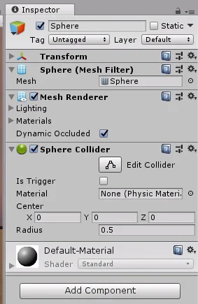
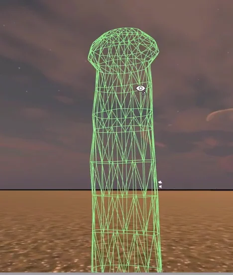
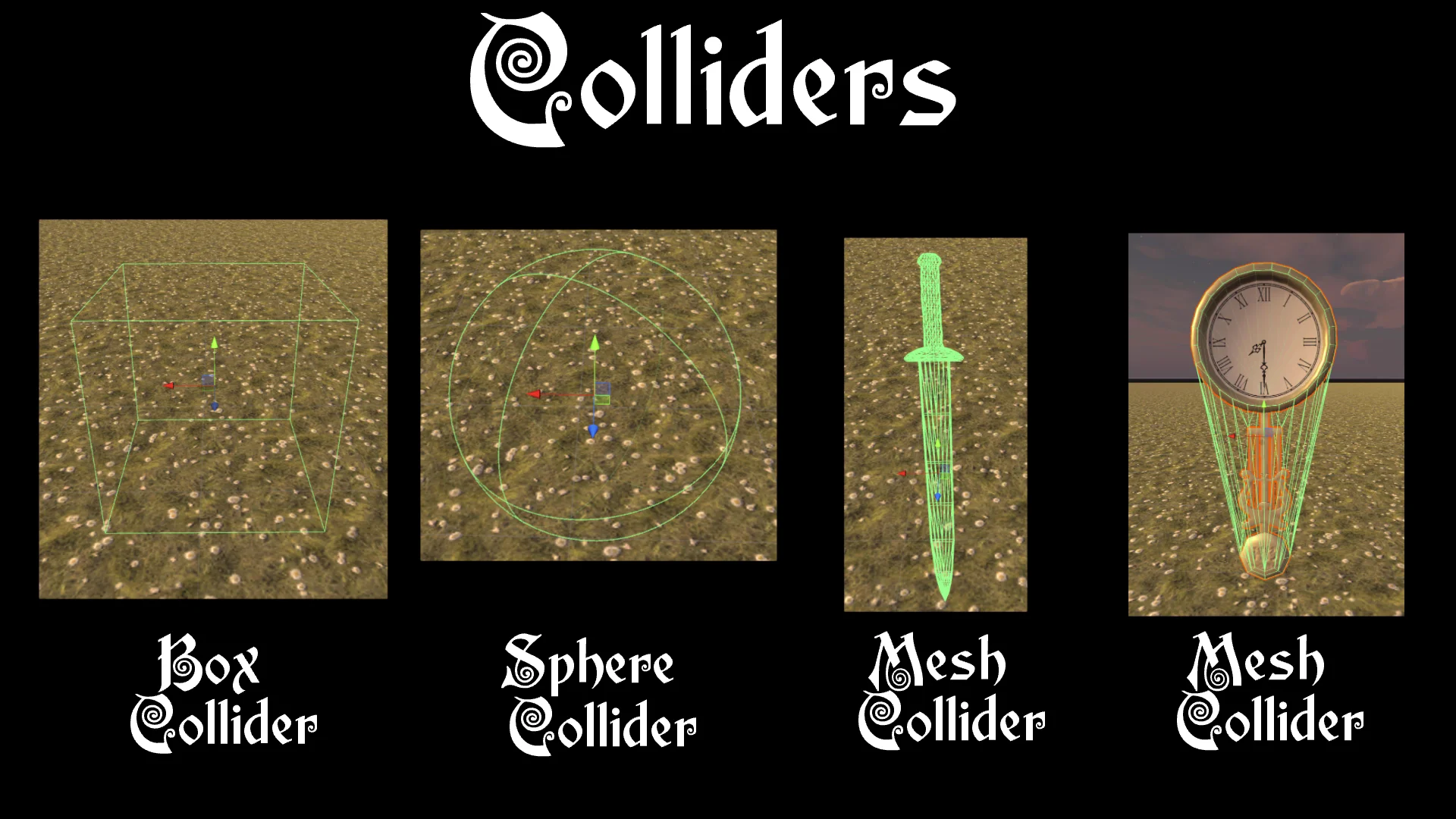
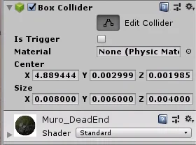
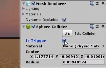
Other components such as Colliders use vectors to draw the Collider, define its position and size. In figure 5 we see an example of Collider in three dimensions in which three component vectors are used and in figure 6 an example of Collider 2D in which two component vectors are used.
Fig. 5: 3-component vectors in for the diensions of a Collider.
Fig. 6: 2-component vectors for the dimensions of a 2D Collider.
In addition to the Unity components, in our Script we can create vectors to use in our algorithms.
The name of the object by which we refer to these vectors in a C# Script for Unity is Vector2 and Vector3. We can see some examples in figure 7.
Fig. 7: Examples of the use of mathematical vectors in Scripts C#, in Unity.
Conclusion
Vectors in mathematics are a useful tool for representing trajectories and forces.
A vector has a module that determines its size, a direction that determines its orientation in space, and a sense within that direction.
Given a vector we can find a single line that contains it.
Updated information about this project
This article belongs to a series that consist on making a first person game about finding objects inside a maze. It’s one of my very first series from the channel. Now I reworked this project and you can download it to import in your own Unity project. Some day I will make a new series about this project, subscribe to my channel to see all the fresh content about Blender, Unity and programming.
Follow me on itch.io and download the source code of this project
YOU CAN TRY THIS GAME HERE, IT MAY TAKE A LITTLE WHILE TO LOAD 🔻
MOVEMENT: WASD CAMERA LOOK: MOUSE
Introduction of the old article
In this article we are going to see a way to place collectable objects in Unity, these objects will be watches that when collecting them will add time in the countdown.
We must establish rules and make an exhaustive description of the behavior of the clocks, for example how they will interact with the character, how they will appear on the stage, etc. The better the description, the easier it will be to create a solution using programming.
What we are looking for is that a certain number of clocks appear in the labyrinth. We must make sure that these clocks do not appear inside the walls and do not overlap each other.
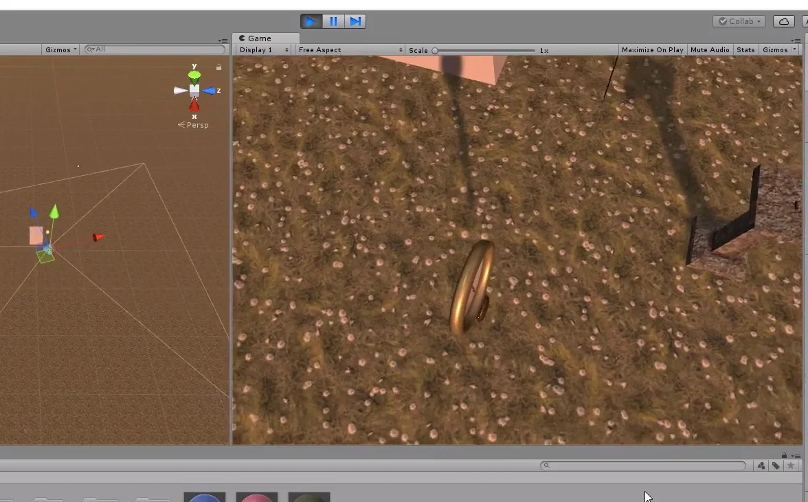
Fig. 1: The clocks will appear in random positions in the labyrinth.
In addition, I am going to make sure that each piece of the labyrinth can contain only one watch, in this way we do not run the risk of placing two superimposed watches.
To achieve this we must keep a record of the pieces of the labyrinth that have a clock inside, so when we are going to place a new clock, those pieces will not be considered in the selection.
When the character takes a watch, a certain number of seconds will be added to the countdown.
Every time a watch is destroyed, a new one appears on the stage, so that all the time we will have the same number of watches on the stage.
Resolution
Previous steps
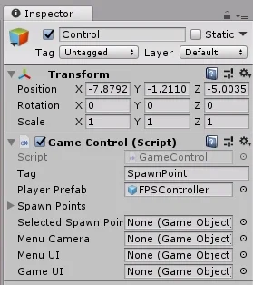
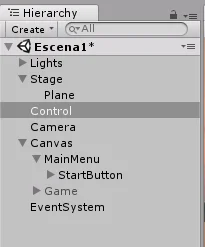
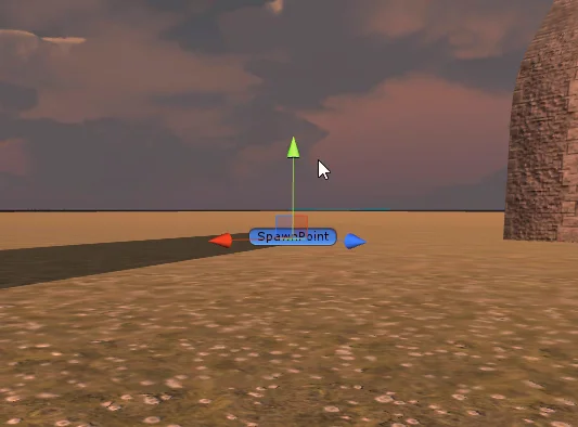
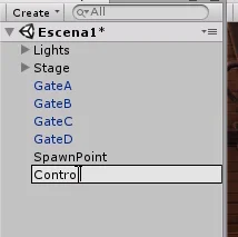
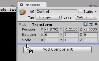
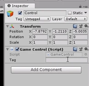
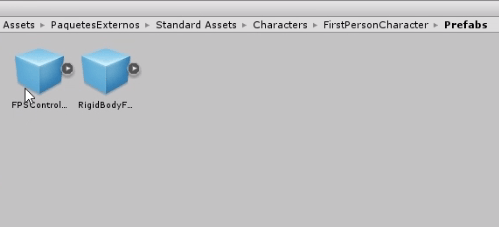
We start by selecting GameObject Control from the hierarchy and assigning it the tag “GameController”. Then select the GameObject FPSController and assign the tag Player.
Fig. 2: Select the control object and assign the tag “GameController”.
Fig. 3: Select the player’s prefab and assign the tag “Player”.
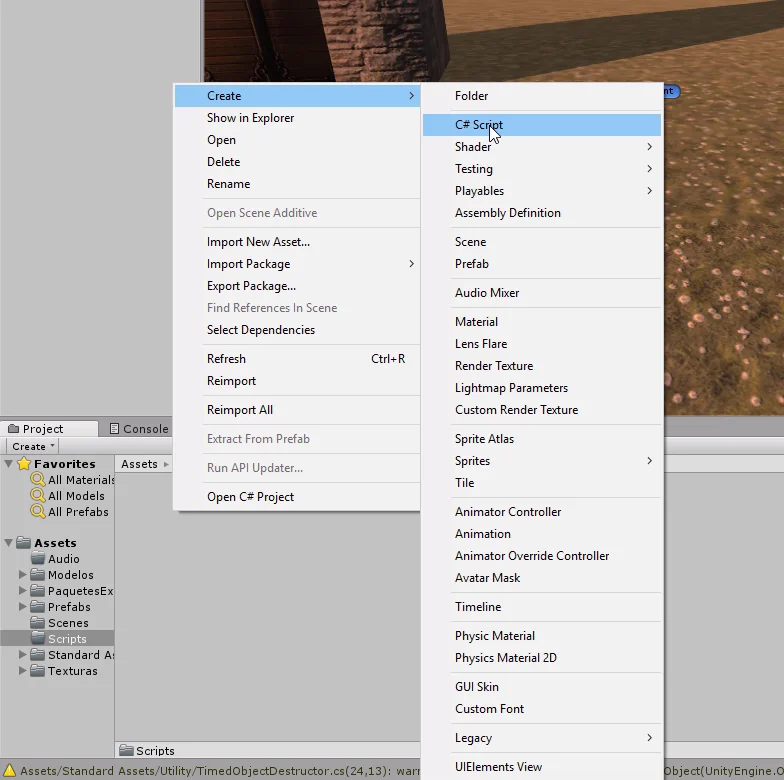
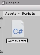
Next we are going to create a new Script called Clock, which we will later assign to the prefabricated clock.
Fig. 4: We create a new script with the name “Clock”.
This script will model the behavior of clocks.
Fields of Clock Script
We are going to define a serialized String that we will call “playerTag”, this variable will contain simply the name of the tag that we have assigned in the player.
Then we will define a float type variable to indicate the life time in seconds of the clock on the stage.
We define a GameObject called labyrinthPiece with “get” and “set” as shown in Figure 5, this way it will be a parameter that can be read and written. I usually like to define public methods to access variables, but this is a very practical way to do it.
Finally we define a GameControl type object because the clock needs to inform the control what is happening.
Fig. 5: We define these fields for use in the solution.
Methods of Clock Script
First we define the SetLifeTime public method with float parameter that we will use so that the GameControl object assigns a certain life time to the clock.
Then there’s the SelfDestruction method that will run when the clock’s life time runs out or the character grabs it.
The Collect method will run when the character picks up the clock, alerts GameControl and then self-destruct.
Finally the OnTriggerEnter method to detect the character, when this happens we will execute the Collect method.
Fig. 6: We define these methods to use in the solution,
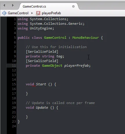
Fields in GameControl Script
Let’s go to the GameControl Script and define four serialized fields.
ClockPrefab will contain the prefab of the clock that we will place on the stage. The nClocks integer will indicate how many clocks should be placed on the stage. The float clockLifetime will be the average lifetime of a clock on the stage. Finally the whole timePerClock will indicate how many seconds are added to the Timer after the character takes a clock.
Fig. 7: In GameControl we are going to define some fields to solve the problem.
GameControl Script Methods Statement
The PlaceAllTheClocks method will make sure that it is possible to set the indicated number of clocks and then run the PlaceAClock method as many times as clocks need to be set.
ClockDestroyed will be executed by a clock that has just self-destruct, that way the GameControl Script will be able to re-consider the maze piece where the clock was and place a new clock in a random position.
ClockCollected will be executed by a clock when the character comes into contact with it, this way we can add time to the timer.
Finally, the DestroyAll method will destroy everything that must be destroyed at the end of a game (pedestal, clocks, character, etc.).
Fig. 8: We define some methods in GameControl.
Clock Method Instructions
To start in the Clock Start method we find the reference of the GameControl object, then we invoke the selfDestruction method in a time that is the result of the sum of the life time of the clock with a random value between 0 and 1. In this way we achieve that the clocks are not destroyed in the same frame.
Fig. 9: In the Clock Start method we are going to find the reference of the GameControl component and invoke self-destruction.
In the SelfDestruction method, we inform the GameControl object that a clock has been destroyed and pass the maze piece assigned to the clock as a parameter, so that the GameControl object can remove it from the exclusion list. Then we run the Destroy method with parameter “gameObject” so that the object destroys itself.
Fig. 10: In SelfDestruction we are going to tell the Control that the clock was destroyed and then run the Destroy method.
In the Collect method we are first going to cancel the pending invocation of the selfDestruction method. Then we inform the GameControl object that a clock was collected. Finally we run the selfDestruction method.
Fig. 11: The Collect method informs the event control and then self-destruct.
In the OnTriggerEnter method we are going to ask if the tag of the Collider that touched the clock is the one of the player and if this is true we are going to execute the Collect method.
Fig. 12: If the Collider that comes into contact with the clock has the tag “Player” we will execute the Collect method.
GameControl Methods Instructions
PlaceAllTheClocks Methods
In the PlaceAllTheClocks method of GameControl we will read the amount of labyrinth pieces we have available to place the clocks. If it turns out that more clocks must be placed than the number of labyrinth pieces, let’s make nClocks equal to the number of labyrinth pieces minus one, this way we’ll prevent the program from entering into an infinite loop.
Then we will do a loop executing the PlaceAClock method to place a clock on the stage.
Fig. 13: In the PlaceAllTheClocks method we will put all the clocks on the stage.
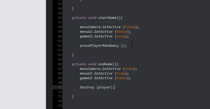
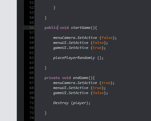
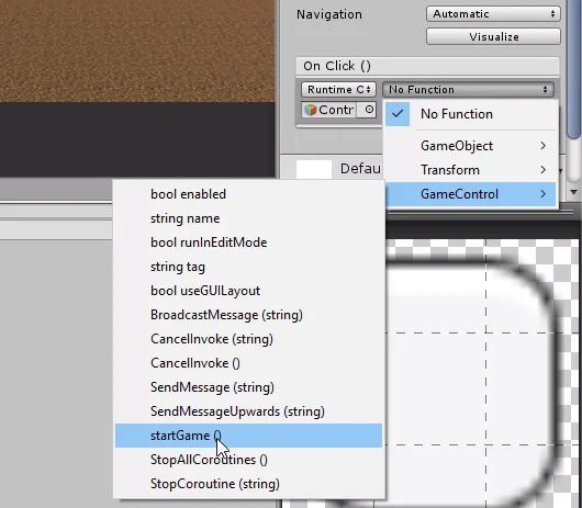
StartGame Method
In the StartGame method we are going to create the GameObjects List object (line 182 of figure 14).
To create the object is very important, so much so that in a computer exam in which it was necessary to write code on paper, I forgot to place the new instruction to create the object and I subtracted almost 40 points from 100. When I went to defend my exam they considered that they had exaggerated a little given that it had been my only error and they forgave me.
Fig. 14: In GameControl Start we create the list object and then execute the PlaceAllTheClocks method.
PlaceAClock Method
Returning to the subject of methods, in PlaceAClock we have to randomly choose a piece from the labyrinth assuring us that the piece no longer contains a clock, once we get it, we ask for a random position of its interior. To solve this it is necessary to have solved the exercise of the previous article, in which we created the Script Labyrinth Piece.
The algorithm for placing the watch part can be seen in figure 15.
Fig. 15: The PlaceAClock method will choose a piece from the labyrinth and place the watch.
ClockDestroyed Method
In the ClockDestroyed method we are going to remove from the list the piece of the labyrinth that is passed to us as a parameter and then execute the PlaceAClock method to place a new clock in the scenario.
Fig. 16: In Clock Destroyed we removed the maze piece containing the watch from the list and placed a new watch.
AddSeconds Method of Timer
We need to define a public method within Timer that allows us to add a number of seconds to the timer.
At the end of the script we make the declaration of the AddSeconds method, we will complete it at the end.
Fig. 17: In the Timer Script we are going to add a public method to add seconds to the timer.
Returning to the GameControl Script, in the ClockCollected method we make the call to the AddSeconds method of timer, passing as parameter the whole timePerClock.
Fig. 18: In the Clock Collected method we are going to add seconds to the countdown.
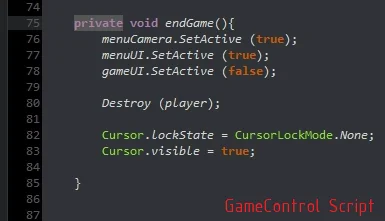
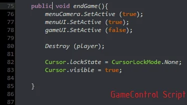
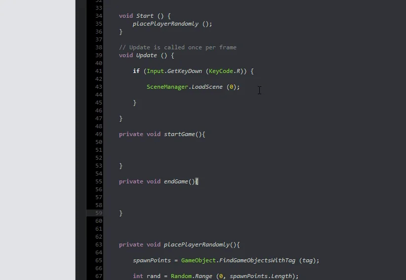
Now let’s go to the EndGame method, where the Destroy lines are, let’s run the DestroyAll method and cut the two Destroy instructions that we had previously placed in other items.
Fig. 19: Let’s go to the EndGame method, cut the destruction instructions and execute the DestroyAll method.
We paste those two instructions into the DestroyAll method and then find all the clocks on stage and destroy them using a foreach loop.
Fig. 20: In DestroyAll we paste the previously cut instructions and remove all clocks from the stage.
Setup Clock Prefab
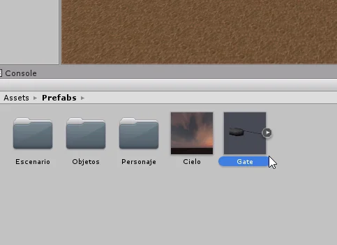
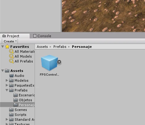
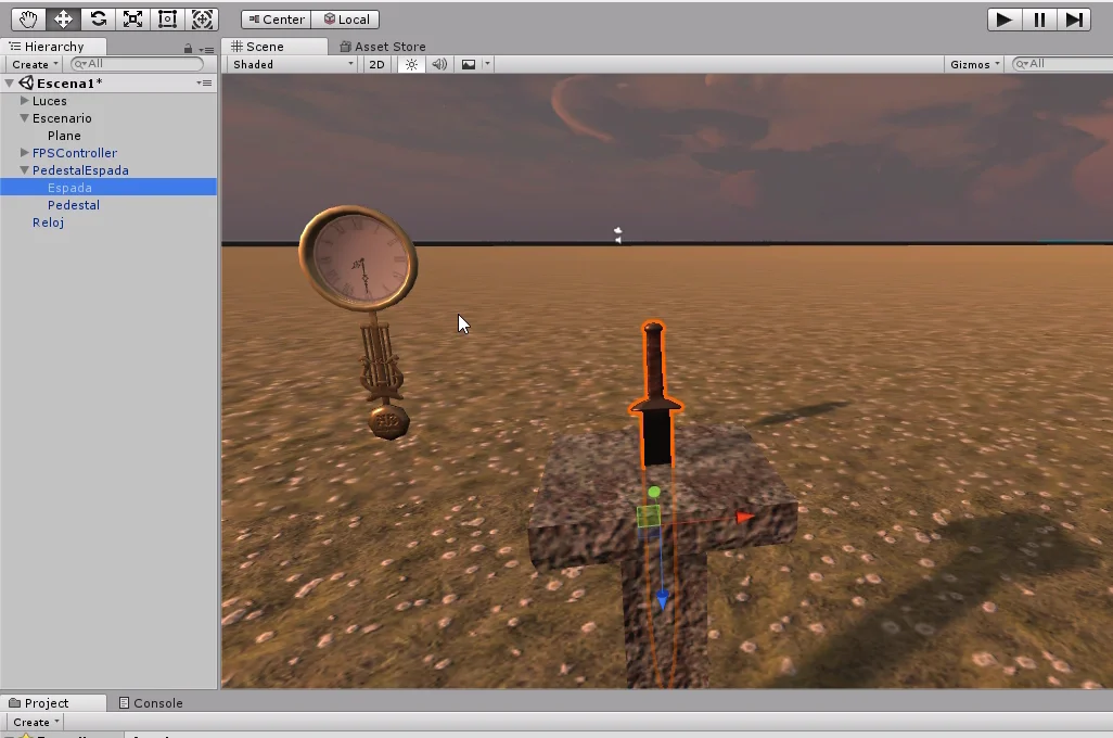
Now let’s select the prefabricated clock from the project folder and drag it to the scenario to set it up.
Fig. 21: Select the prefab of the clock.
We create the Clock tag and assign it to the GameObject of the clock.
Fig. 22: We created a new Tag called Clock.
Fig. 23: We assign the Clock tag to the prefab of the clock.
Fig. 24: Clock with the assigned tag.
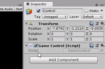
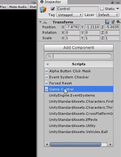
Then drag the Script Clock to its components or use the AddComponent button. Then we introduce “Player” in the tag field (figure 25).
Fig. 25: Assign the Script Clock to the prefab of the clock and enter the player’s Tag.
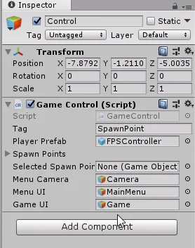
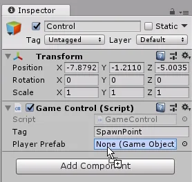
Let’s go to GameObject Control and enter the new parameters that we had previously defined.
Fig. 26: Select the Control object and set the new parameters in the inspector.
Now let’s complete the AddSeconds method of the Timer Script that we had pending.
Inside we will simply increase the seconds, adjust the minutes and execute the WriteTimer method to update the values.
Fig. 27: Back to the Timer Script and complete the AddSeconds method.
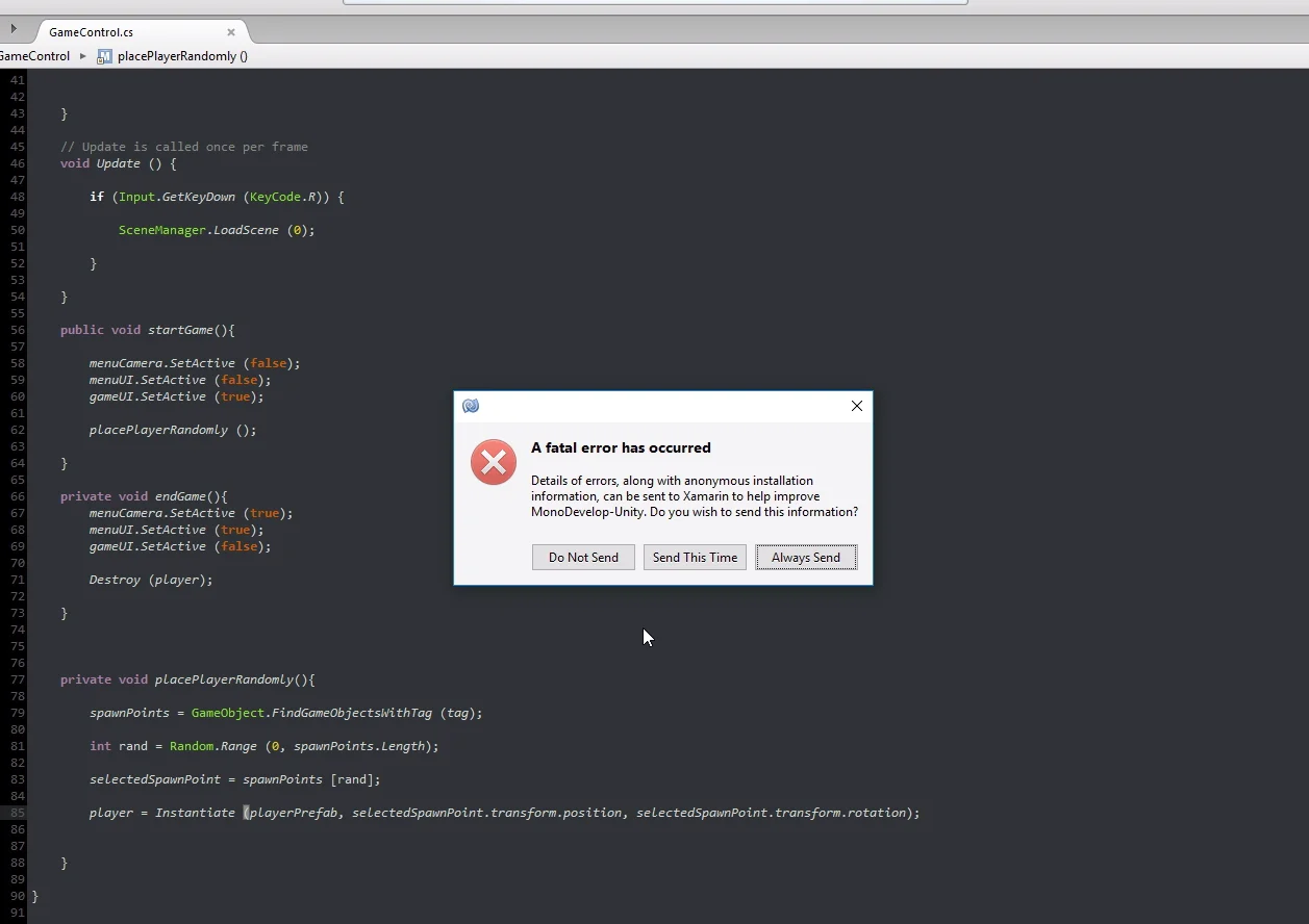
Programming error
At this point an error appeared in the console saying that there is no version of the PlaceAClock method that does not have parameters.
Fig. 28: An error occurs saying that there is no method definition that does not contain parameters.
I go to line 184 of the GameControl Script where the error appeared, in effect we see in figure 29 that the execution of the PlaceAClock method is done without parameters.
Fig. 29: I go to the instruction where the error is located.
I define the integer nPieces with the value of the amount of elements in the labyrinth parts list and enter this integer as a method parameter.
Fig. 30: I define an integer with the number of labyrinth pieces and pass it as parameter to the method.
Bug correction
When I test the game, the clocks didn’t seem to have appeared on the stage. When I paused the simulation and searched the hierarchy, I discovered that they had appeared but were upside down, as shown in figure 31.
Fig. 31: When running the game we find a bug, the clocks appear face down.
To correct this bug I go to the method where a clock is placed on the stage and I look for the instruction in which I make the Instantiate, instruction 173 in figure 32.
Instead of giving the new GameObject the rotation of the Quaternion identity I’m going to give it the rotation that is defined in the prefab of the clock, which when placed on the stage appears correctly oriented.
Fig. 32: I go to the point where I place the clocks on the stage.
Fig. 33: Instead of using Quaternion.Identity I use the rotation defined in Prefab.
Final Details and Test
When I tried the game, I noticed that there were few watches and that they gave up very little time when I picked them up.
In order to balance the elements correctly it is necessary to make several tests and see what works best, in addition this can form part of a system of difficulty in which a high difficulty implies less frequent clocks that deliver little time when picking them up.
Fig. 34: I adjust the values in GameControl to give me more time to collect them.
In figure 35 we have two clocks in front of nostors and the timer marks approximately one minute fifty, the figure 36 was taken moments after grabbing the two watches, we see that the Timer now marks a little more than two minutes ten. This concludes the problem.
Fig. 35: In the scene two clocks are observed in front of the character and the time indicates 1:47.
Fig. 36: After picking up both watches, the time is 2:13.
Conclusion
In this article we have seen how to randomly place collectables in Unity, these collectables were the clocks that when collecting them had to add time to the countdown.
The object GameControl is in charge of placing them on the stage randomly using the solution created in the previous article to place the pedestal randomly in a piece of the labyrinth.
To solve the problem we have created a Script that will model the behavior of the clock and will exchange messages with other Scripts to report events such as a self-destruction or that the character has picked up the clock.
The effect of collectable element we do it simply executing appropriate actions when the character passes over them.
Updated information about this project
This article belongs to a series that consist on making a first person game about finding objects inside a maze. It’s one of my very first series from the channel. Now I reworked this project and you can download it to import in your own Unity project. Some day I will make a new series about this project, subscribe to my channel to see all the fresh content about Blender, Unity and programming.
Follow me on itch.io and download the source code of this project
YOU CAN TRY THIS GAME HERE, IT MAY TAKE A LITTLE WHILE TO LOAD 🔻
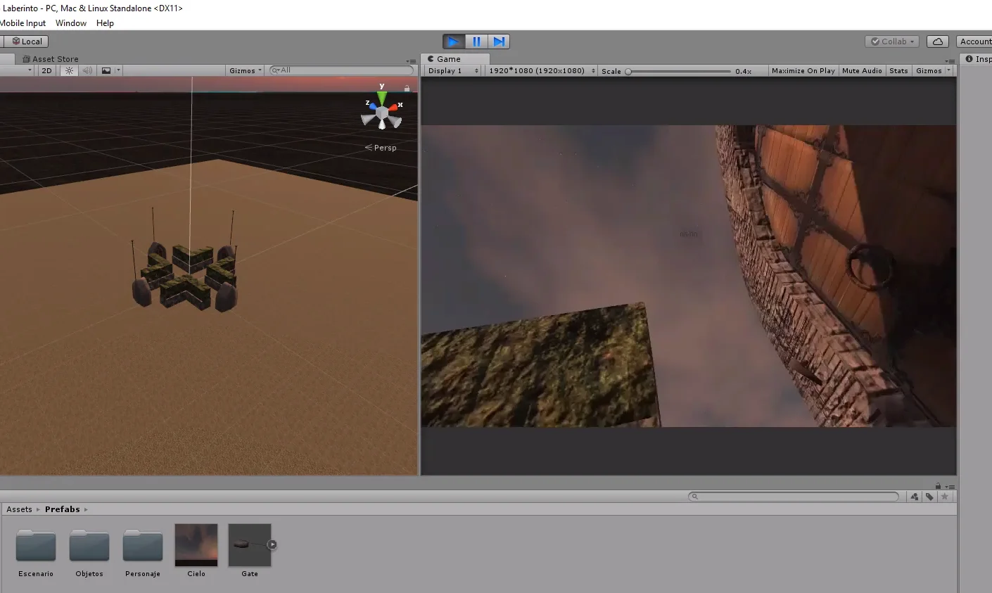
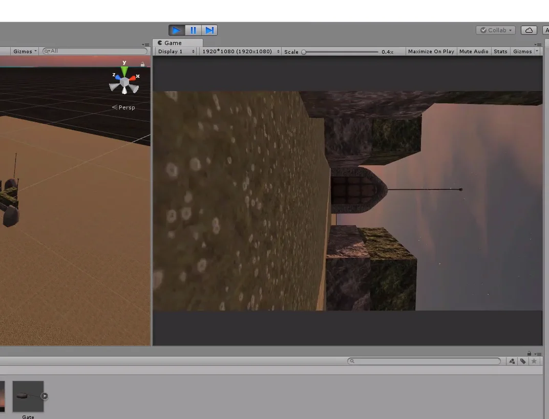
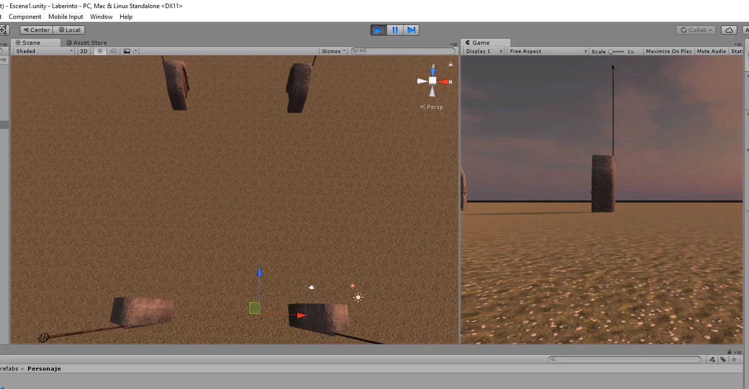
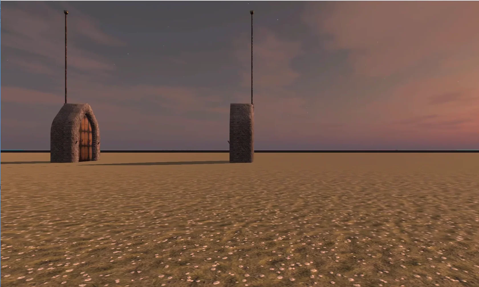
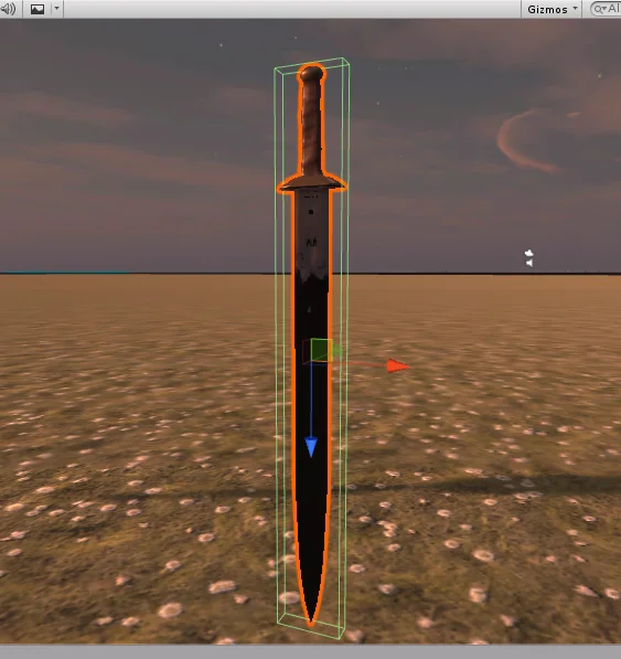
Fig. 1: El pedestal con la espada aparece en una posición aleatoria del escenario.
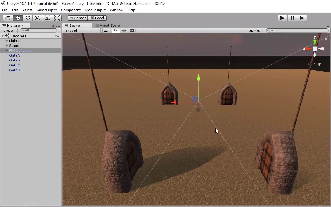
Fig. 2: En el video y artículo 4 colocamos al personaje aleatoriamente en una de las puertas.
In video 4 we use empty GameObjects to designate specific positions in which to place the character’s prefab.
In this case we are looking for a more complex solution, first we are going to choose one of the pieces that compose the labyrinth. The piece we choose will be a duplicate of one of the pieces shown in figure 3.
Fig. 3: These are the pieces of the labyrinth in which you can walk.
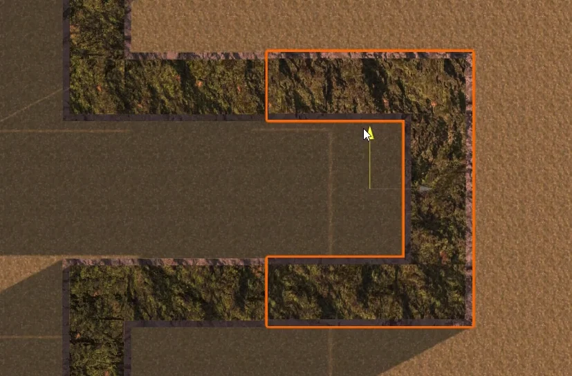
It is not enough just to choose the piece, we need to obtain a position within it and this position must be within a region in which you can walk. We see these regions in figure 4.
Fig. 4: In these regions we will be able to place the pedestal.
When analyzing the problem we see that we will have to make several random decisions and it would be desirable that the solution we propose is independent of the number of pieces that the labyrinth has. In other words, if we add more pieces from figure 4, they are automatically added to the selection system.
Strategy: Define Segments
Given one of the pieces in figure 4, we are able to draw one or two internal lines where the player can circulate within the piece.
Let’s consider the ends of these two lines. Figure 6 identifies four points that would be the ends of these two segments.
These points could be represented with Empty GameObjects as children of the piece.
Fig. 5: Crossroads of the labyrinth.
Fig. 6: At the ends of the piece we place 4 points.
In figure 7 we see these two segments drawn.
Then we could place the pedestal with the sword at any point of one of the segments.
Fig. 7: These points form two segments, horizontal and vertical.
First of all, let’s choose one of the two segments, let’s suppose segment B (figure 8) formed by empty GameObjects B1 and B2.
Then we’ll take a random point between the two empty GameObjects, figure 9.
Fig. 8: Suppose we choose segment B.
Fig. 9: We choose a random point of segment B.
Finally at that chosen point we will place the pedestal.
Fig. 10: At the chosen point, place the pedestal with the sword.
In the case of the pieces of the corridor and dead end that only have one direction, we will make coincide the points A and B, that way we will have two coincident segments, then we will be able to use the same solution that for the rest of the pieces.
Fig. 11: In the case of the corridor, we will make segments A and B coincide.
Implementation of the strategy
We have worked out a plan to place the pedestal somewhere inside one of the pieces of the labyrinth. Now based on this we are going to solve the problem.
First in the hierarchy I’m going to separate the obstruction pieces from the others, because these pieces are not going to be considered in our solution.
In the figure 1 we see selected the pieces that we are going to use.
Fig. 12: Select the labyrinth and separate the obstructing parts.
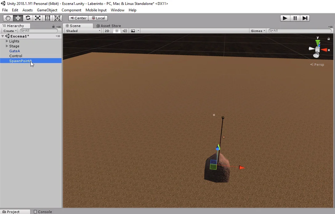
We need to find the references of these pieces in our code to be able to choose one of them. The simplest way to do this is to use a Tag.
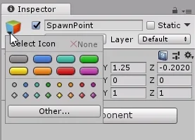
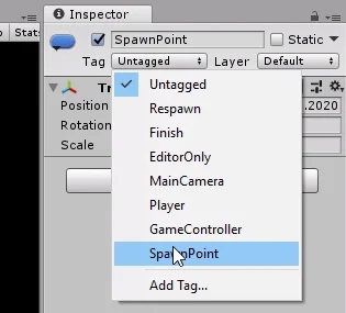
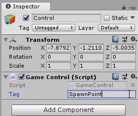
Fig. 13: We create the SpawnPiece tag for the pieces that can contain the labyrinth.
I’m going to create a Tag called “SpawnPiece” and assign it to all the pieces selected in figure 12.
Fig. 14: We select all the parts that can contain the pedestal.
Fig. 15: The selected pieces are assigned the SpawnPiece tag.
Next we create the Script “LabyrinthPiece” (labyrinth piece) that will be assigned to all the pieces selected in figure 12.
Fig. 16: We create a new script called LabyrinthPiece, which we will assign to the parts that can contain the pedestal.
In the Script first we will define four GameObjects that will be points A1, A2, B1 and B2. We declare them as serializable fields so that they appear in the inspector and we can assign them manually.
Fig. 17: We define four GameObject type fields to contain the points of each piece.
We select any piece type Crossroads and assign the Script LabyrinthPiece. In figure 19 we see that in the inspector appear the fields for GameObjects.
Fig. 18: In the hierarchy we select the crossroads.
Fig. 19: We assign the Script LabyrinthPiece to the crossroads.
Next we’re going to create the four empty GameObjects that we’ll call A1, A2, B1 and B2. In figure 20 we see created the first point. Note that it is defined as the son of an Empty GameObject called Spawn, which in turn is the son of the crossroads piece.
Fig. 20: We created four empty GameObjects as sons of this piece.
We are going to position these four objects according to figure 6, at the ends of the imaginary segments that represent the walkable area inside the piece.
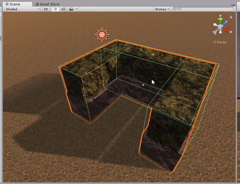
Fig. 21: Using the orthographic perspective, we position the empty GameObjects, one at each end.
Fig. 22: Using the orthographic view, we position the empty GameObjects, one at each end.
We assign these objects to their respective fields in the inspector, within the LabyrinthPiece component.
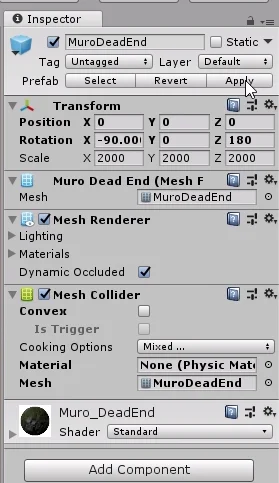
Finally we apply the changes. This is very important because we are applying the changes on the Prefab of the crossroads, that is to say that all the crossroads of the labyrinth will now have their own objects A1, A2, B1 and B2 and will have assigned the component LabyrinthPiece, with their own points loaded in the fields.
Fig. 23: We assign the empty GameObjects to the spaces in the inspector.
Fig. 24: We apply the changes so that all the crossroads of the scenario have the same configuration.
We can check that by checking every crossroads in the hierarchy and checking that it has these points and the Script assigned to it.
Fig. 25: When applying the changes, all the labyrinth crossroads become empty objects and the Script LabyrinthPiece.
What follows is to repeat the process for the other pieces. In figure 26 we see the T-shaped piece, this case is similar to the bifurcation only that one of the imaginary segments will have its end in the center of the piece.
Fig. 26: Empty objects for the bifurcation piece.
In the corridor piece we create only points A1 and A2. In figure 28 we see that these points are also assigned in fields B1 and B2 respectively.
Fig. 27: Empty objects for the aisle piece.
Fig. 28: For the aisle part we assign points A1 and A2 also to fields B1 and B2.
In the corner piece, figure 29, the imaginary segments will have two coincident points, we could create only three Empty GameObjects and one of them assign it for example to A2 and B1, but we chose to create the four points.
Fig. 29: Empty objects for the corner piece.
The case of the dead-end piece is the same as that of the aisle only with less distance.
In figure 31 we see that in points B1 and B2 we repeat points A.
Fig. 30: Empty objects for the dead-end piece
Fig. 31: For the dead end piece we assign points A1 and A2 also to fields B1 and B2.
Method for choosing a random position of a piece – Random.Range
In the Script LabyrinthPiece we are going to create a public method that will return a Vector3 that will indicate a random position of the piece.
The first instruction will be to declare a Vector3 called position which will be the one we return to at the end of the execution.
Let us remember that they are two imaginary segments formed one by points A1 and A2, another by points B1 and B2. So then let’s do an if to choose one segment or the other.
In the if argument we use Random.Value to generate a random number between 0-1 and check if this value is less than 0.5f. This means that we will have a 50% chance of choosing segment A and another 50% of choosing segment B.
To choose a random point of the imaginary segment formed by the points we use the Vector3.Lerp method, which will make a linear interpolation between two Vectors3 that we indicate.
The method receives three arguments, the first two are the Vector3 between which it will be interpolated and the third parameter is the interpolation point we are interested in.
To exemplify the interpolation function consider the following: if the third value of the Lerp method is 0 we will have a Vector3 equal to the first parameter indicated. If it is worth 1 we will have a Vector3 equal to the second parameter indicated. And if it is worth 0.5f we will have a Vector3 that will be located exactly in the central point between the two Vectors3 that we indicate as parameters.
In this way we use Random.Range to generate a Vector3 that will be in some position between the points indicated in the first two parameters of the Lerp method and we assign that vector to the Vector3 position that we had defined at the beginning.
In an if region we use the position of points A1 and A2. In the other if region we do exactly the same but with points B1 and B2.
Finally we return the Vector3 position.
All this explained is summarized in the 7 lines of the GetRandomPosition method in figure 32.
Fig. 32: The GetRandomPosition method will deliver a random position inside the part.
Now, this we did was for the Script LabyrinthPiece that is assigned to each piece of the labyrinth.
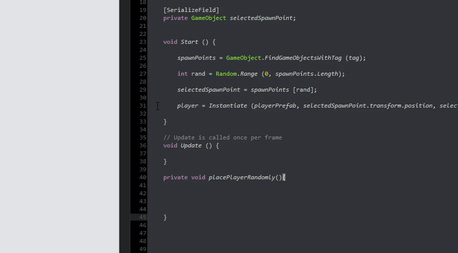
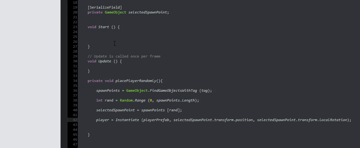
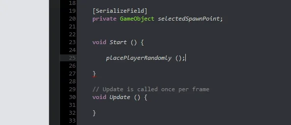
In the GameControl Script we are going to create a method that will place the pedestal in a random position in the labyrinth and make use of the public method of LabyrinthPiece.
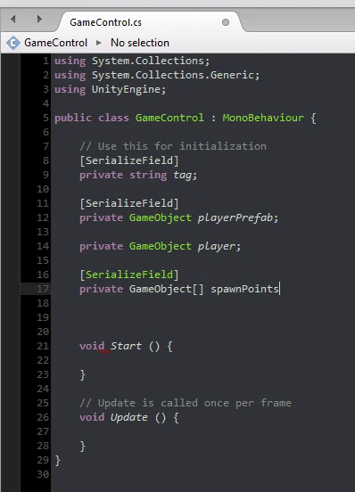
We begin by defining the fields shown in figure 33 below the comment “//Video 9”. These are the fields and variables that we will use to solve the problem.
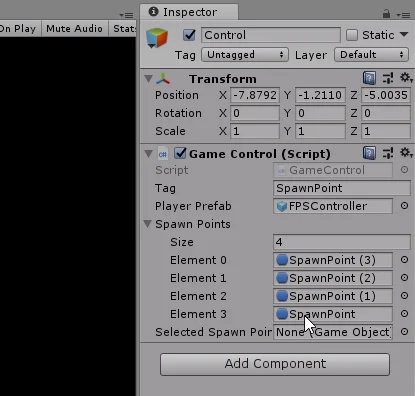
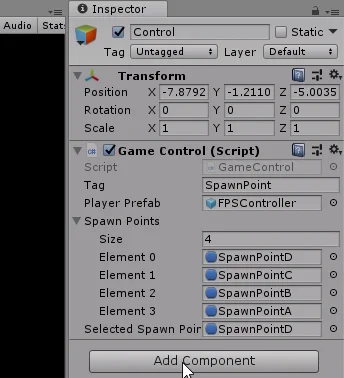
Fig. 33: In the GameControl Script we define a GameObjects array for the labyrinth pieces.
In the GameControl component in the inspector (assigned to GameObject Control), fill in the fields. In SpawnPieceTag type “SpawnPiece”.
Fig. 34: We write the name of the tag that we assign in the pieces of the labyrinth, in this case “SpawnPiece”.
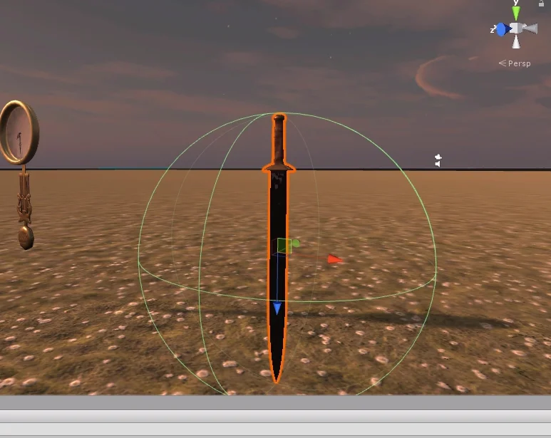
In ObjectToFind we will assign the Prefab of the pedestal with the sword, which is the object to find.
Fig. 35: We looked for the prefab of the pedestal with the sword we made in video 2 of the series.
In the minimum distance for the moment we write the value 75. Then we will see what this variable is used for.
Fig. 36: Assign the Prefab of the pedestal to the ObjectToFind field.
It is not necessary that the LabyrinthPieces array appears in the inspector so I am going to remove the [SerializeField] selected in figure 37.
Fig. 37: It is not necessary for the GameObject array of labyrinth pieces to be visible in the inspector.
Fig. 38: It is not necessary for the GameObject array of labyrinth pieces to be visible in the inspector.
Fig. 39: When removing the SerializeField line, the field does not appear in the inspector as it is private.
In the StartGame method we are going to find all the GameObjects of the hierarchy that have the Tag that we indicate in the inspector. Last instruction of the startGame method in figure 40.
Fig. 40: In the GameControl Start method we find all GameObjects with the indicated Tag.
Then we declare the PlaceObjectToFind method (figure 41) and call this method from the StartGame method (figure 42).
Fig. 41: We define a private method that will be in charge of placing the pedestal in some part of the labyrinth.
Fig. 42: We make the call from the StartGame method, i.e. when the game starts the pedestal is placed on the stage.
PlaceObjectToFind Method
What we will do with this method is to choose a random piece from the labyrinth, making sure that piece is far enough away from the player using the “minDistance” variable that we assigned 70 in the inspector. If the selected piece does not meet this requirement we will choose another piece again. This is taken care of by the While loop shown in figure 43.
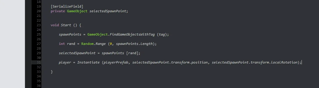
Once we find a part that meets the requirements, we will place the pedestal at a random point inside. For this we use a version of the Instantiate method, which receives three parameters: The first is the object to be found stored in the “objectToFind” field, the second is the position that we will receive automatically from the labyrinth piece executing the GetRandomPosition method of the LabyrinthPiece component assigned to it. The third parameter is the rotation, here we will indicate: Quaternion.identity (a rotation identity).
Fig. 43: Instructions for the PlaceObjectToFind method.
It is important that we save the reference of this new object that we have created, we will do it in “objectToFindInstance” (last instruction in figure 43). This way when the game is over we can destroy this object manually.
In the EndGame method we destroy the instance of the object to be found, figure 44.
Fig. 44: In the EndGame method, the pedestal instance is destroyed.
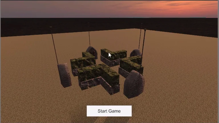
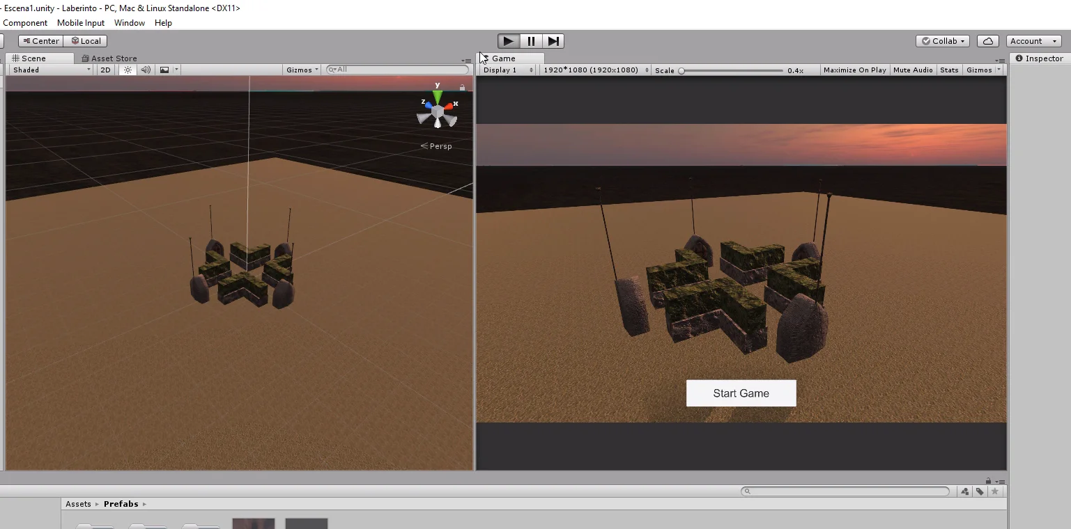
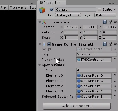
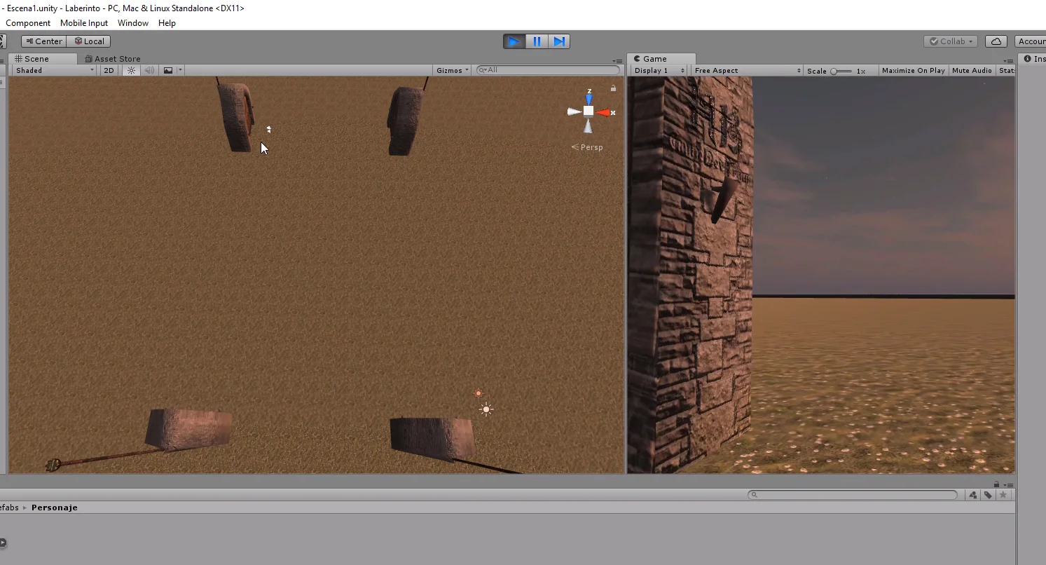
When you enter the game mode and press the Start button, everything seems to be working correctly. The pedestal with the sword appears in a random labyrinth position inside one of the pieces.
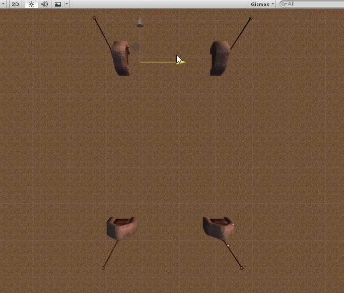
Fig. 45: When entering the game mode the pedestal is placed on one of the pieces of the stage.
Fig. 46: We can see from the editor window which part it is.
Place object in other regions
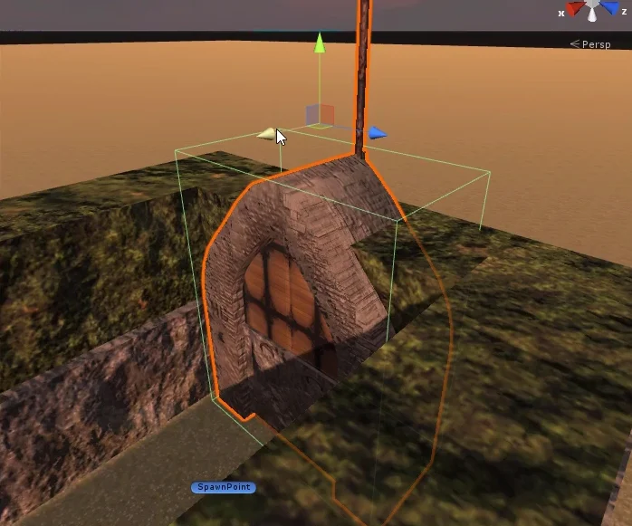
There are regions of the labyrinth that are outside the pieces, for example the one highlighted in figure 47. We might be interested in placing the object in a position belonging to this area.
How could we reuse what we have done?
Fig. 47: This region can be a place where we would like the pedestal to appear.
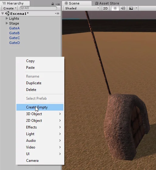
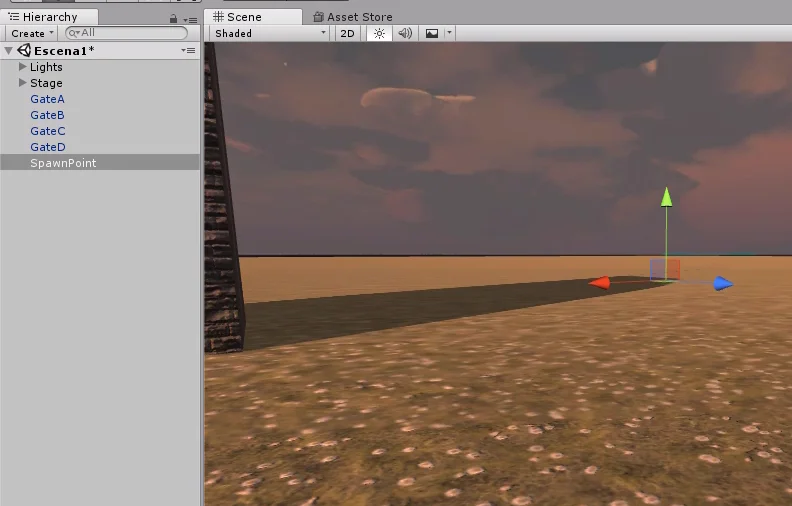
To begin with we created an Empty GameObject and called it SpawnArea and placed it between the pieces of the labyrinth.
Fig. 48: Create an Empty GameObject and call it SpawnArea, this will allow us to place the pedestal in other parts of the labyrinth.
Fig. 49: The four points in the region are children of GameObject SpawnArea.
Then we created four empty GameObjects to represent points A1, A2, B1 and B2. We place these objects at the ends of the two imaginary segments of the area highlighted in green in Figure 49.
Fig. 50: We are going to create 4 empty GameObjects to use in the LabyrinthPiece script.
Then we create a Prefab along with the other pieces of the labyrinth (figure 51), because we may reuse this object by changing the internal points.
Fig. 51: We took the GameObject SpawnArea and created a Prefab for reuse.
Then we assign the component LabyrinthPiece and place the internal points in the respective fields.
Fig. 52: Asignamos el Script LabyrinthPiece al GameObject SpawnArea.
Do not forget to assign the Tag SpawnPiece in the inspector, otherwise these areas will not be considered when choosing a position for the pedestal. In my case, as can be seen in figure 53, I had not assigned it and I spent several minutes testing for the pedestal to appear in these areas.
Fig. 53: We must remember to assign the SpawnPiece tag to the GameObject SpawnArea. Apply changes.
Final Details
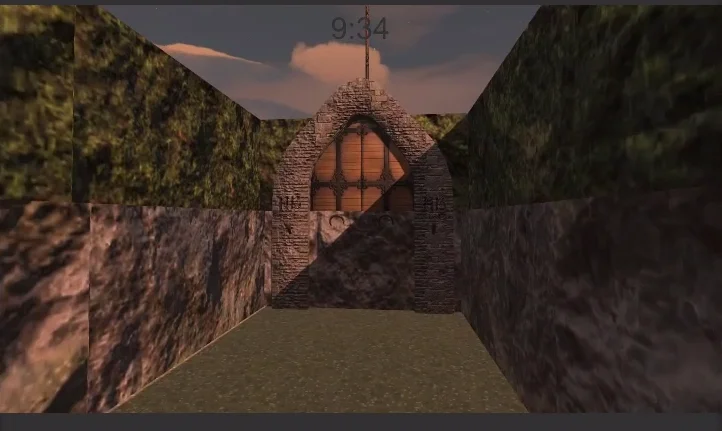
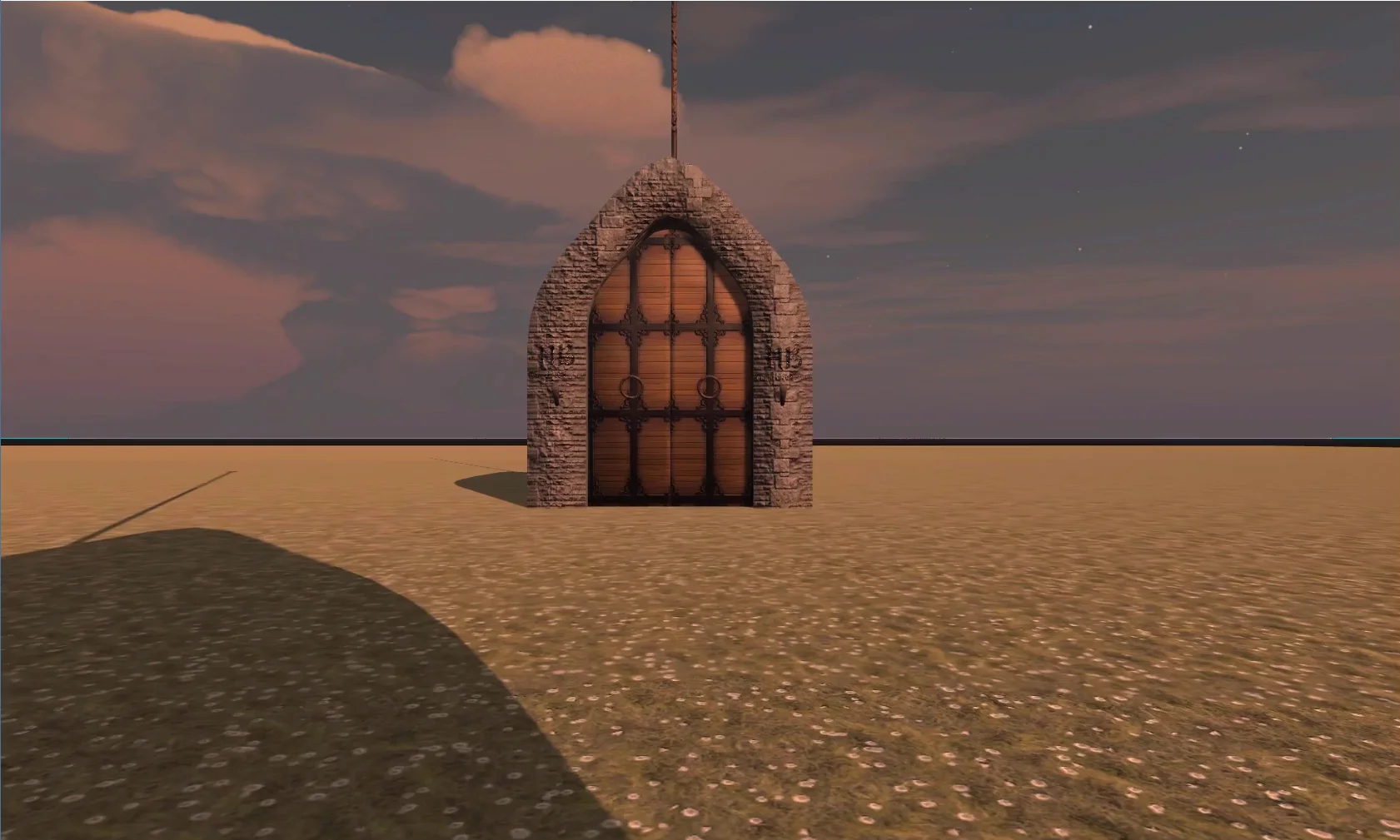
When I tried the game, I noticed that the door was quite large in relation to the character, so I made it a little smaller and applied the changes.
Fig. 54: The doors were too big in relation to the character.
Another problem I detected was that there were pieces with the Tag SpawnPiece whose inner region was inaccessible to the player. In figure 55 you see one of these pieces, if the pedestal appears here, the player won’t be able to find it.
The solution to this is to select this piece and remove the Tag SpawnPiece, this way the piece will not be considered.
Fig. 55: This piece is out of reach of the character, the pedestal does not have to appear here.
Fig. 56: Select that piece and in the tag field select: “Untagged”. We do not apply the changes.
Conclusion
In this article we managed to place the pedestal in a random position within the labyrinth.
To do this we had to analyze the type of pieces that make up the labyrinth, establish certain rules and propose a strategy to solve our problem.
We used object-oriented programming thinking to create a flexible solution that fits all types of parts.
As usually happens, there is no single way to solve a problem. Another way to address this situation is to make a Navmesh Bake and take a point within these regions.
Updated information about this project
This article belongs to a series that consist on making a first person game about finding objects inside a maze. It’s one of my very first series from the channel. Now I reworked this project and you can download it to import in your own Unity project. Some day I will make a new series about this project, subscribe to my channel to see all the fresh content about Blender, Unity and programming.
Follow me on itch.io and download the source code of this project
YOU CAN TRY THIS GAME HERE, IT MAY TAKE A LITTLE WHILE TO LOAD 🔻
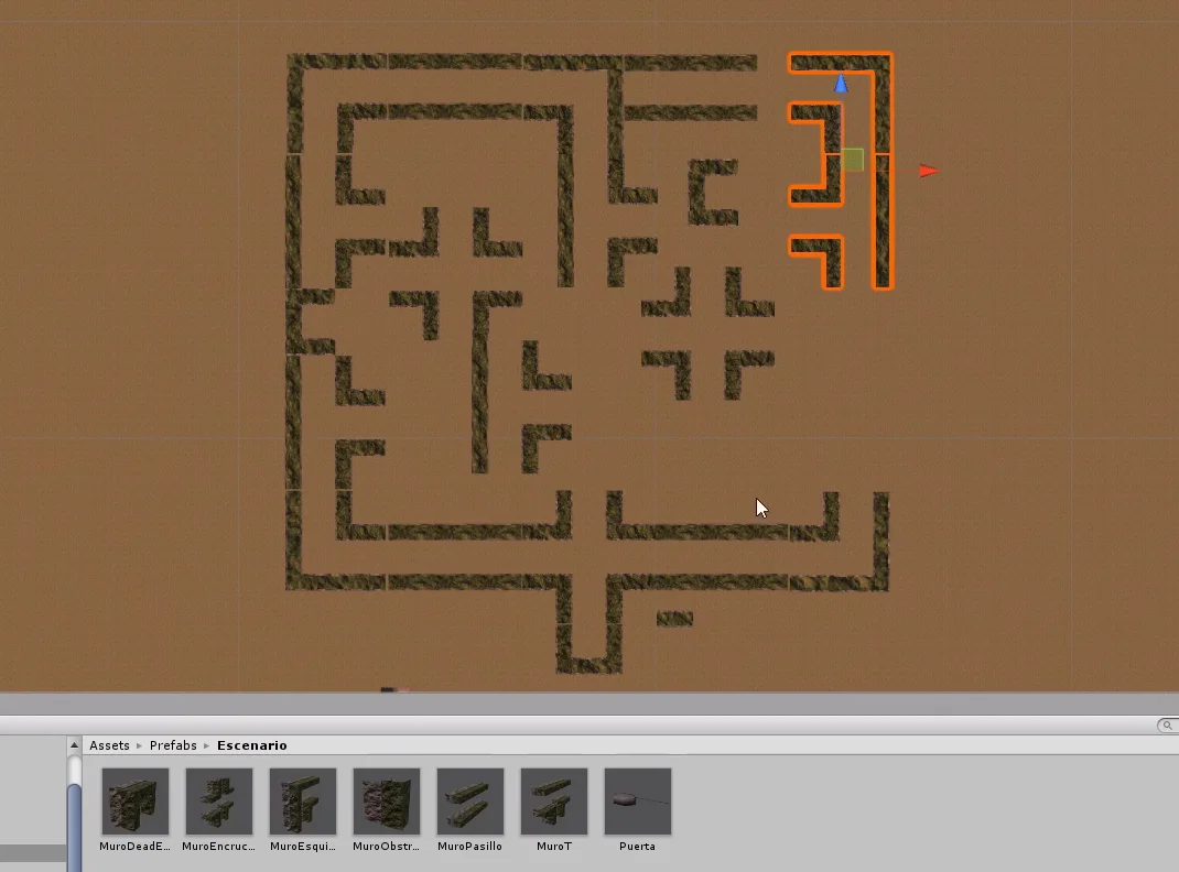
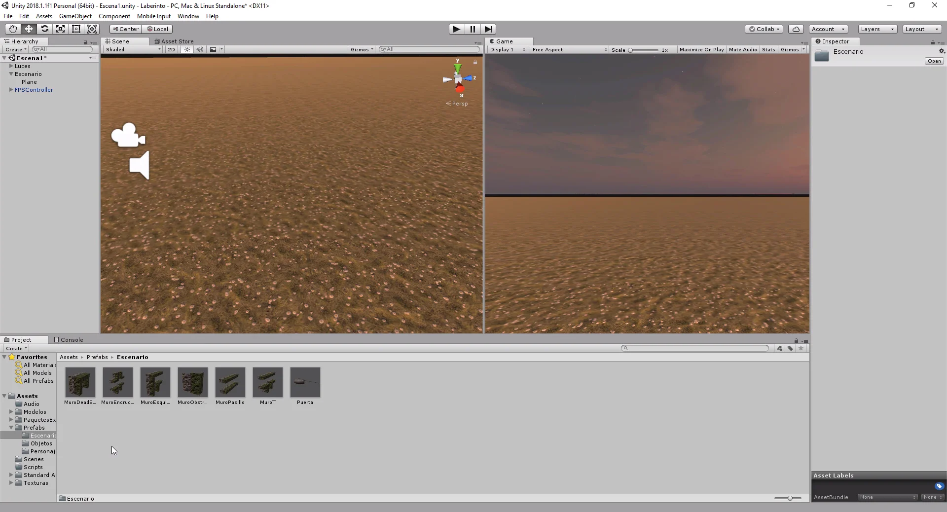
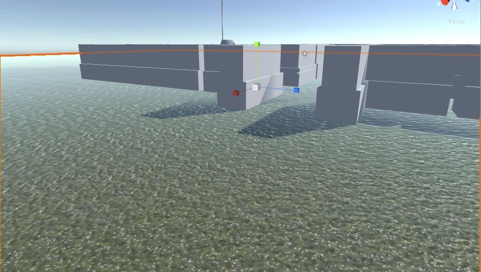
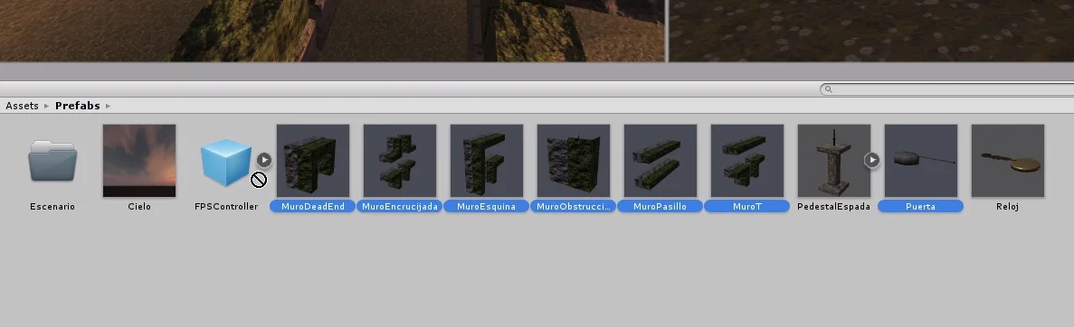
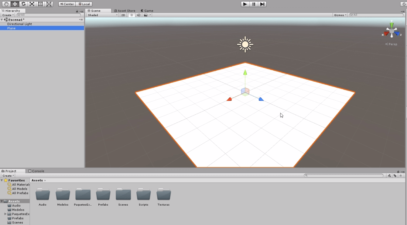
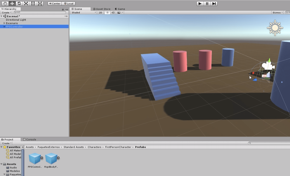
To create a model of the labyrinth we are going to use the prefabricated ones that we created previously, we will place them in the hierarchy and we will begin to duplicate them and to arrange them in the space, as it is observed in the following figure.
Fig. 1: Setting up the stage using the prefabricated elements shown in video 2.
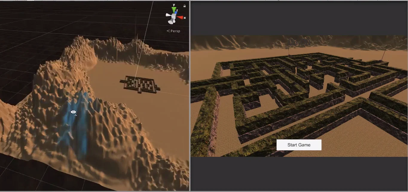
Create terrain in Unity
To create a terrain in Unity we will use the GameObject “Terrain”, which will allow us to modify its relief and textures in a simple way using different brushes and parameters.
Fig. 2: Using Unity tools we can sculpt relief in the terrain.
Download Files
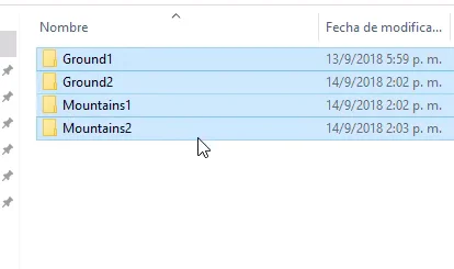
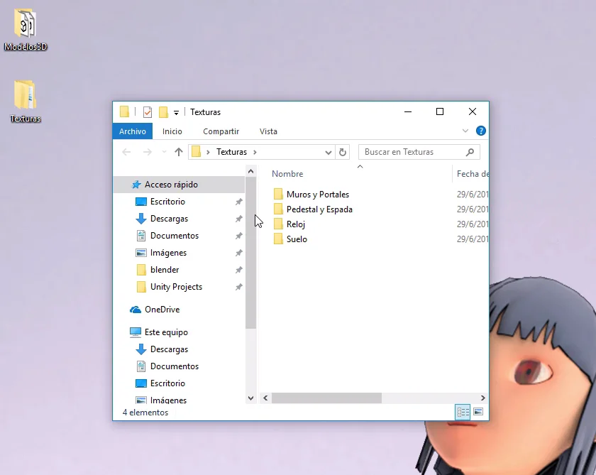
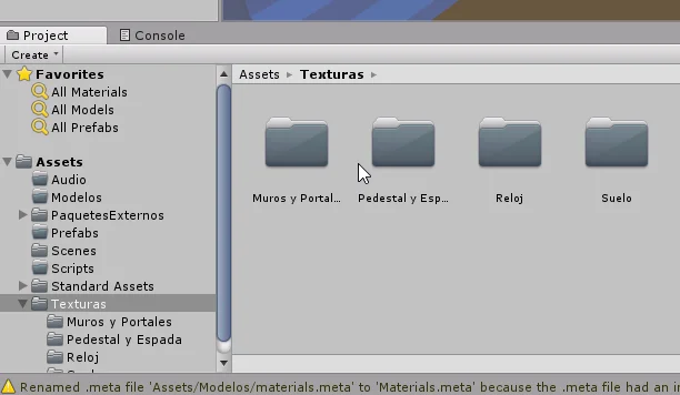
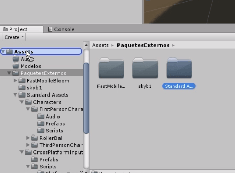
First we download the next Zip file, extract the folders and take them to Unity.
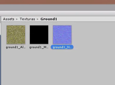
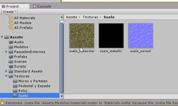
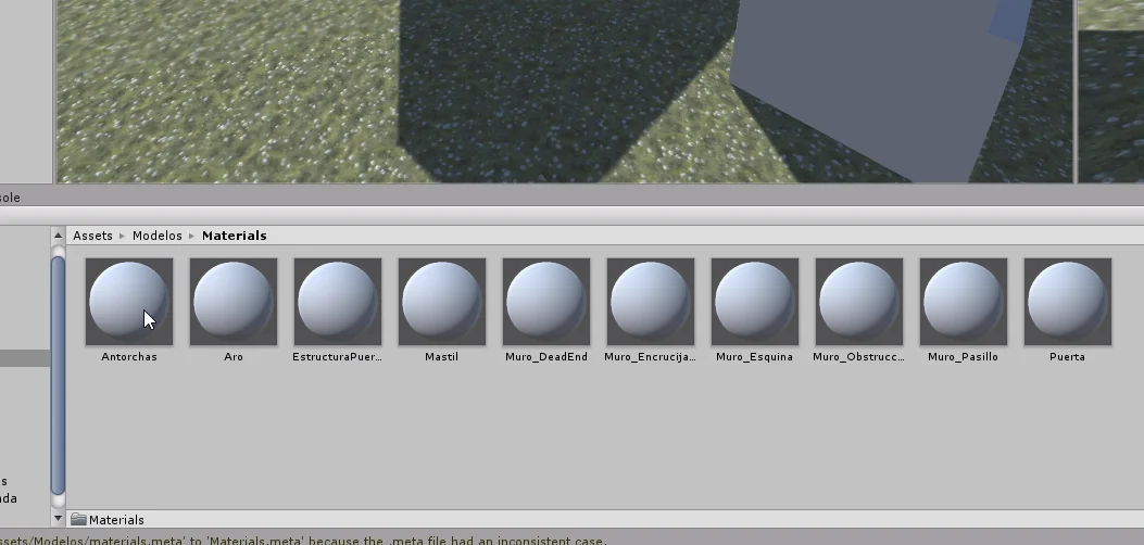
Fig. 3: Extract the textures from the download file to add them to the project.
Fig. 4: Each texture comes with its Albedo, Metallic and Normal maps.
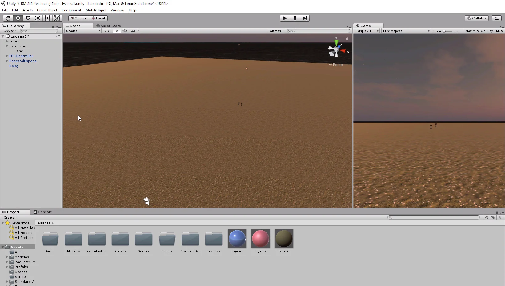
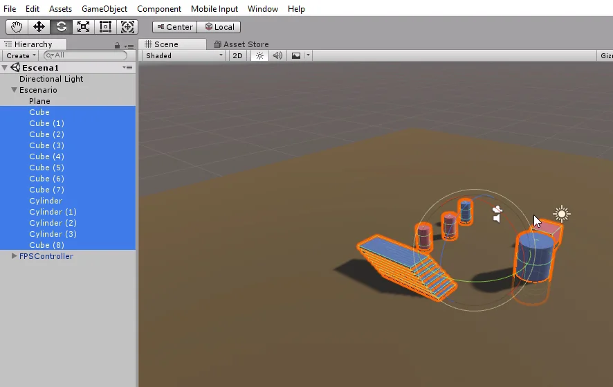
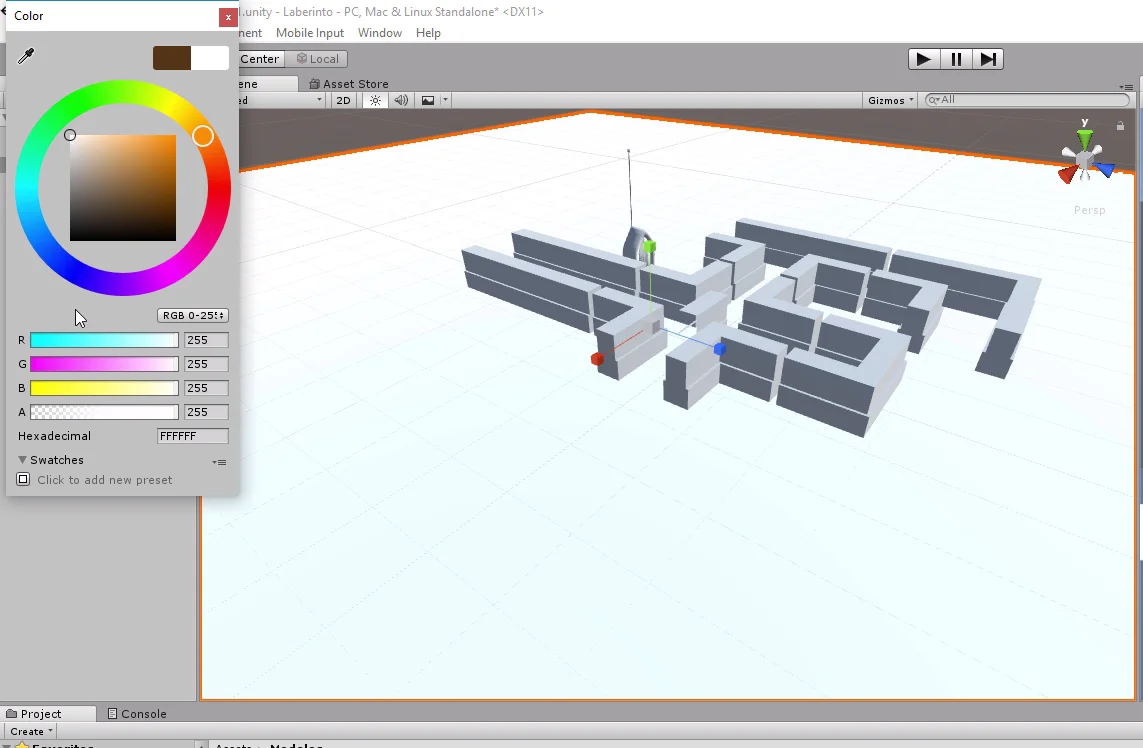
The next thing we do is remove all the elements belonging to the scenario.
Fig. 5: We start by completely cleaning the stage.
Terrain Component – Unity
As mentioned above we will use the Terrain component to create a mountainous relief for the terrain.
This component uses “Height Maps” or height maps to create reliefs, these maps are grayscale textures in which completely black areas are mapped with minimum height and white areas with maximum height (both heights configured in the parameters), the rest of the gray areas will have a height proportional to its color tone.
We can see this in the following image.
Fig. 6: The terrain works with Height maps.
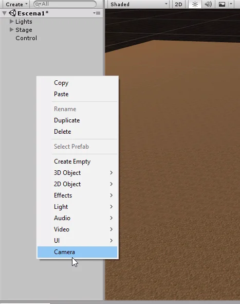
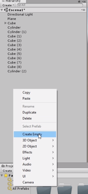
In the hierarchy right click > 3D Object > Terrain.
Fig. 7: From the hierarchy we create a GameObject type terrain.
In the stage a white plane appears and in the inspector we can see that it has two components that define it, the component Terrain and a Collider type Terrain.
Fig. 8: The terrain appears in the scenario and we can see its properties in the inspector.
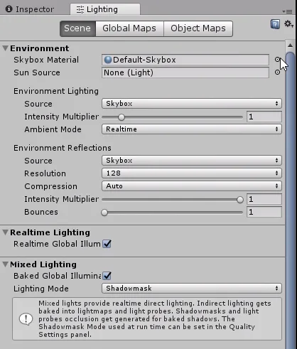
Terrain Component Setup
It is important that we first configure the basic parameters of the terrain, such as the dimension and the difference that will exist between the maximum and minimum height. Then we can modify these parameters but we will probably lose the design we had.
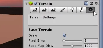
As shown in figure 9, click on the gear icon to go to the configuration. Then enter the parameters.
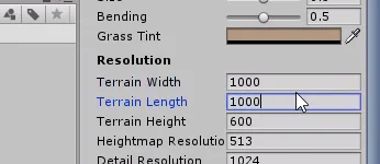
The only thing I’m going to change is the resolution of the land, which will be 1000 x 1000.
Fig. 9: First configure the basic parameters of the inspector.
Fig. 10: We adjust the resolution of the terrain.
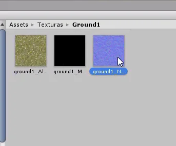
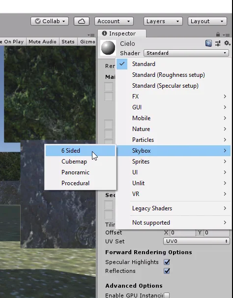
Texture Setup
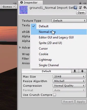
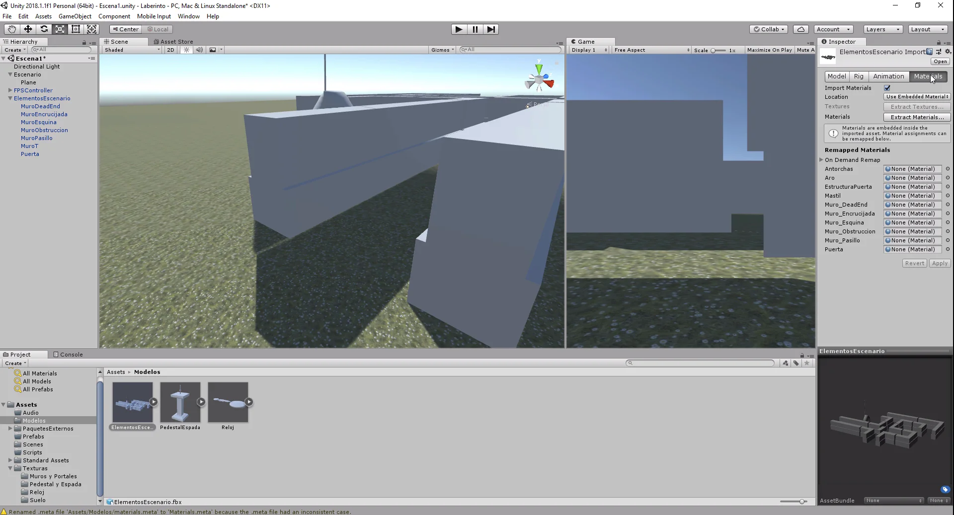
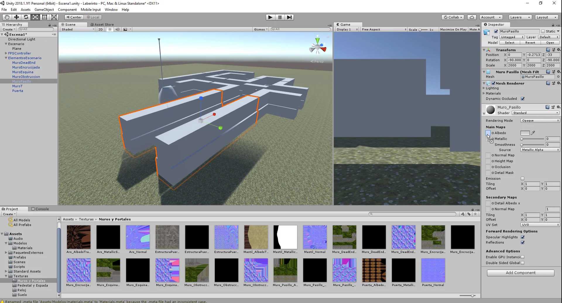
We can paint the terrain using different sets of textures that will consist of Albedo and Normal maps. First we select all the normal maps we have, in the inspector we choose the type of texture as “Normal map” and apply the changes. We do this for all the normal maps we have.
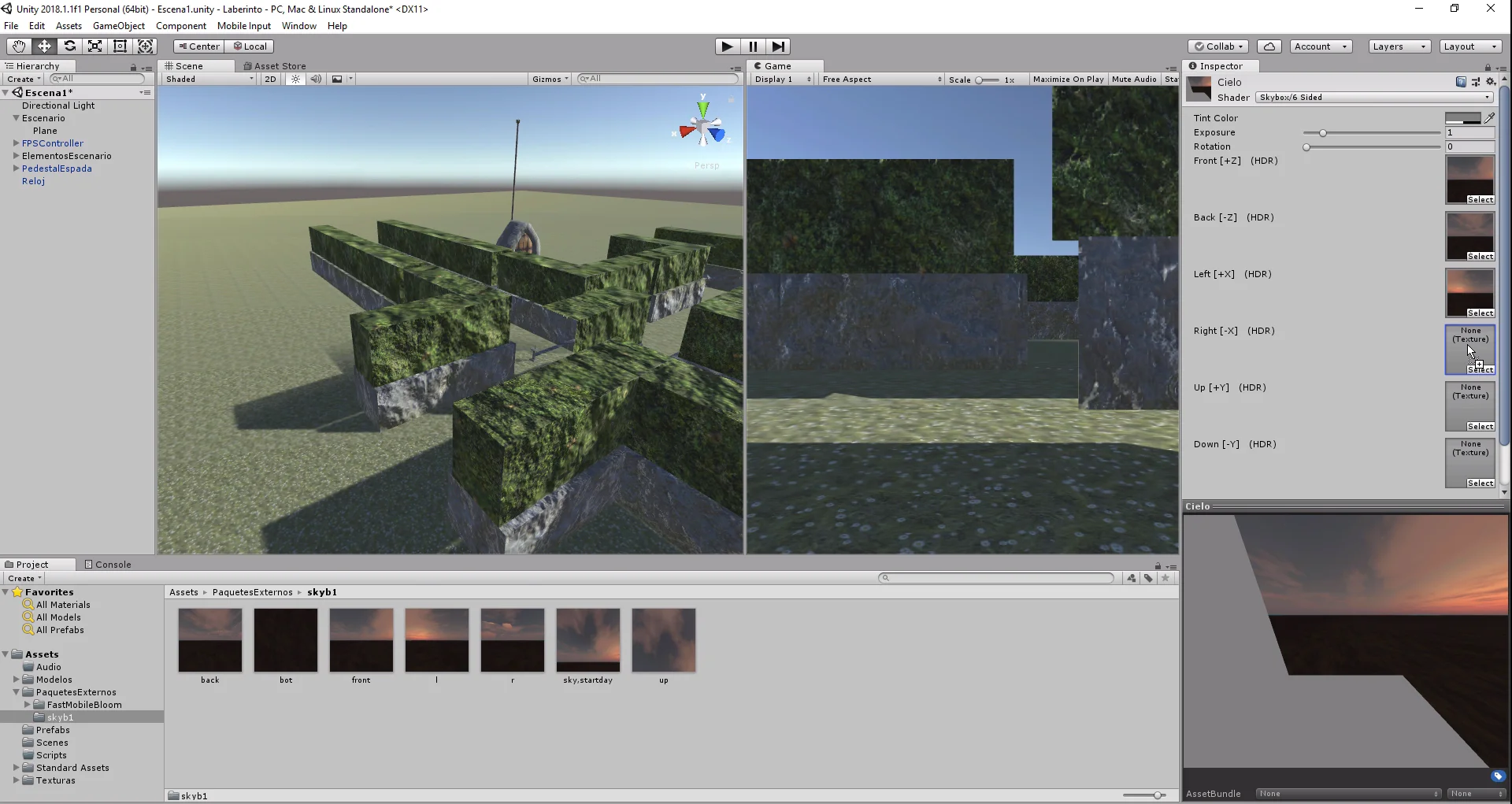
Fig. 11: Select textures such as Normal Map or Normal Map.
Fig. 12: In the inspector we can select the type of texture. Select Normal Map and apply.
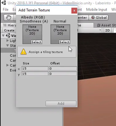
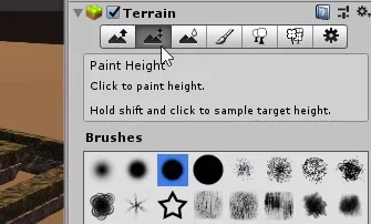
Then select the terrain again and click on the brush icon, then on “Edit Textures…”, “Add Textures” (figures 13 and 14).
Fig. 13: Select the brush tool on the ground component.
Fig. 14: We must configure at least one painting for the terrain.
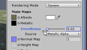
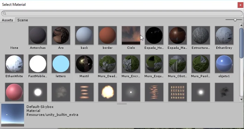
In the pop-up window we can select a texture that represents the Albedo in the RGB channels and its Alpha channel is mapped in the softness. Another texture for the surface Normals. We can also configure the size of the mosaic or TileSize using the fields “Size” and “Offset” that are observed in figure 15.
Fig. 15: In the pop-up window we select an Albedo texture and a normal texture.
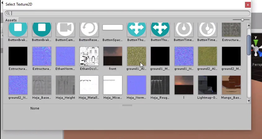
Click on Select and choose first the Albedo map and then the normal map.
Fig. 16: We must make sure to select the appropriate maps.
We’ll do this for all the textures we’ll use to paint the terrain.
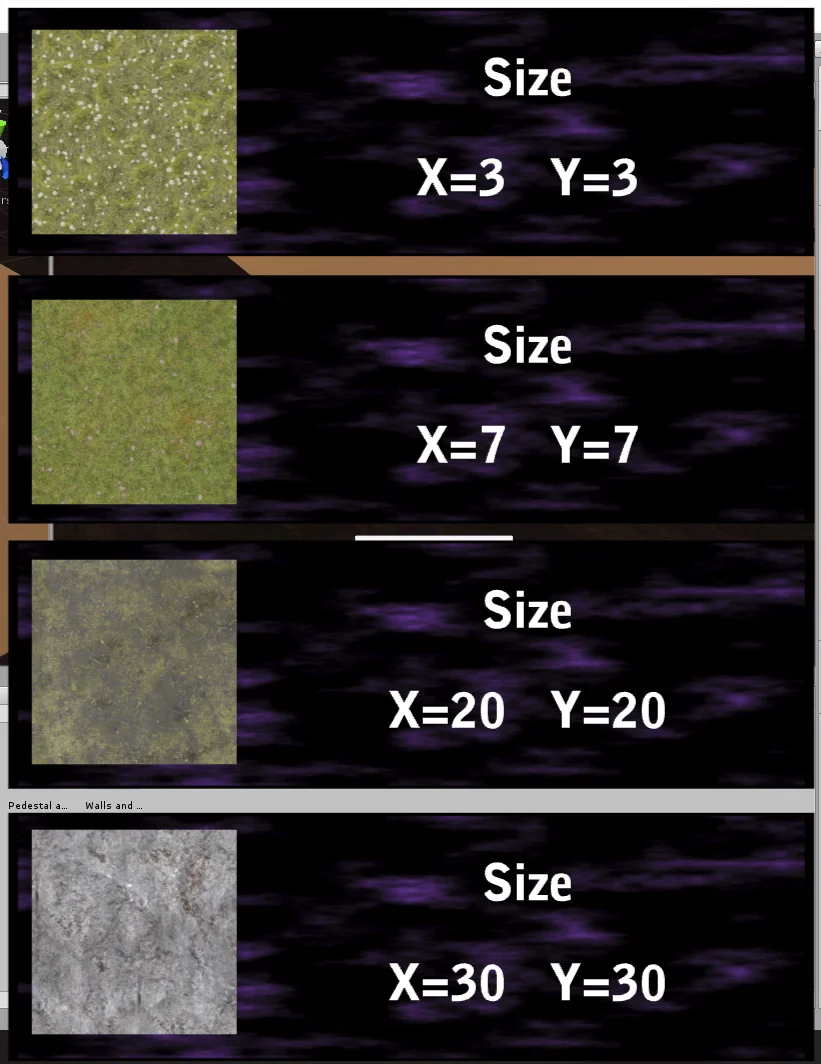
Figure 17 shows some values that work for TileSizes.
Fig. 17: Working mosaic size values.
Once we set up all the textures, we should have them all available for use in the Textures in Inspector window, as shown in figure 18.
Fig. 18: All the textures of the download have been configured.
Making the labyrinth
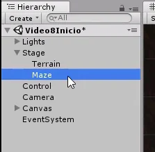
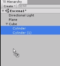
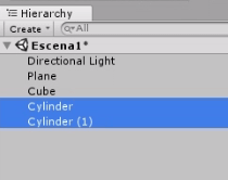
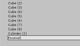
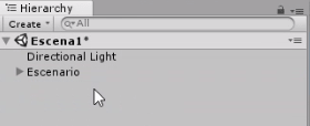
First to keep things tidy I’m going to create an Empty GameObject that I call “Maze”, inside which will be all the prefabricated ones that I use to make the labyrinth.
Fig. 19: We create an empty object that will contain all the pieces of the labyrinth.
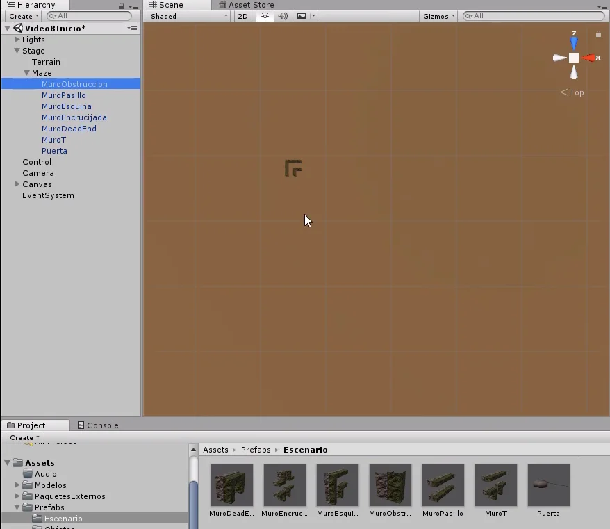
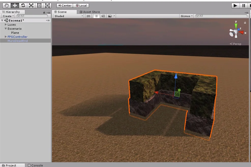
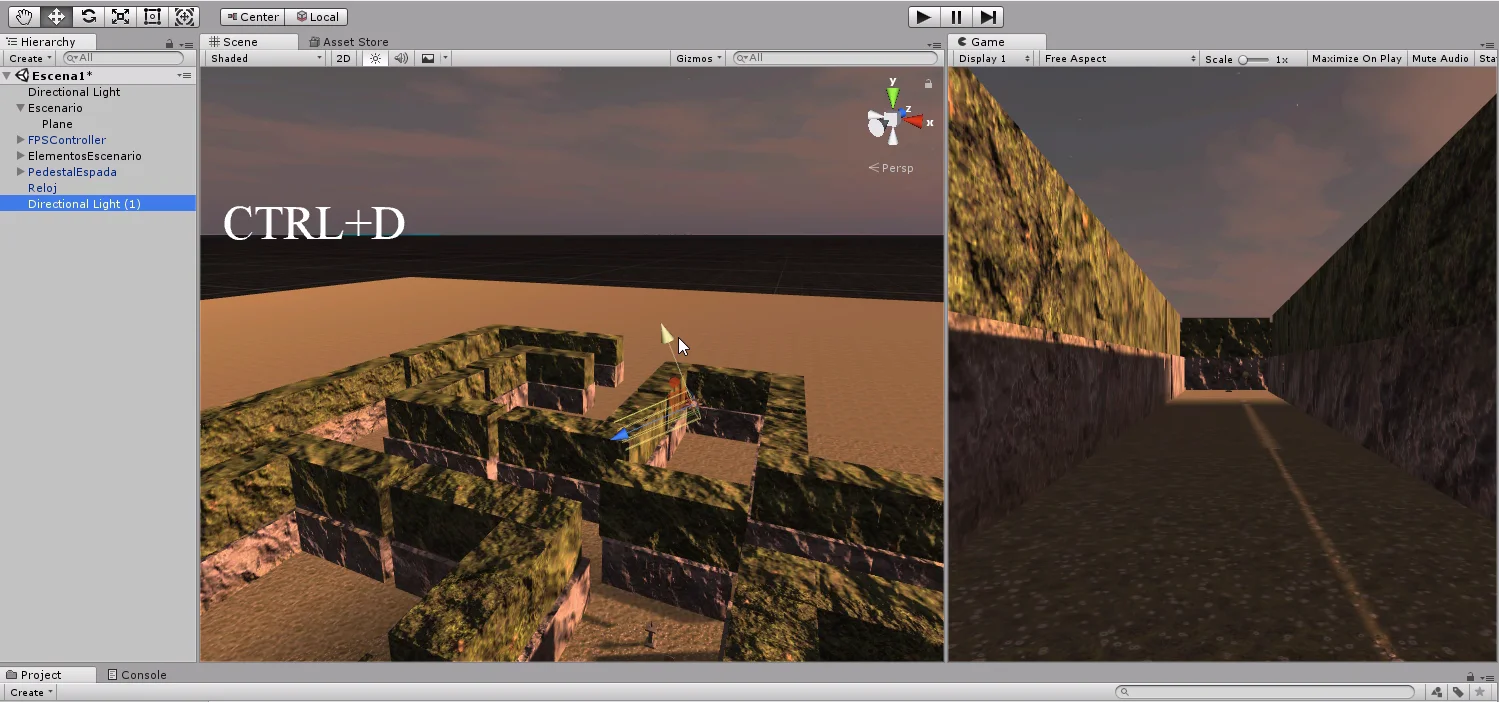
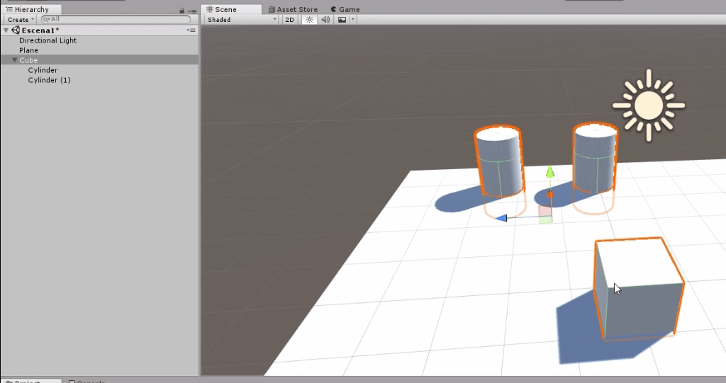
Then I drag all the prefabs to the stage and start duplicating them and moving them to form the corridors.
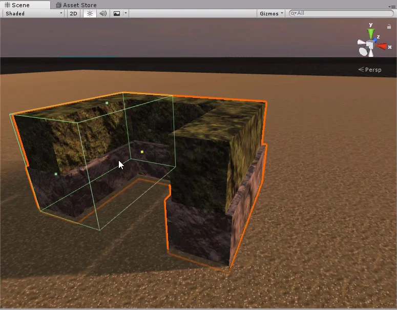
Fig. 20: We start by placing all the prefabricated parts on the stage.
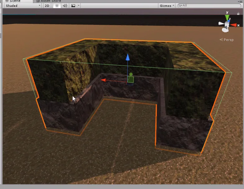
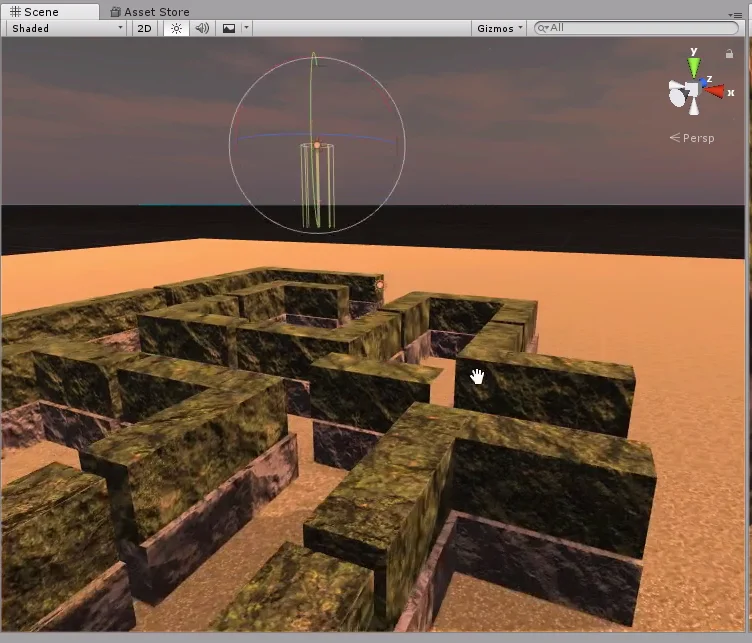
To facilitate the positioning of the pieces we can use the orthographic view. In figure 20 at the top right we have what is called a “Gizmo” that shows the axes X in red and Z in blue. By clicking on these arrows we can change the view of the scene and if we click on the cube in the center we can alternate the view from Perspective to Orthographic.
In figures 20 and 21 we can see how this orthographic view is. The effect it produces is as if all the elements were compressed into one plane, so we do not observe the depth.
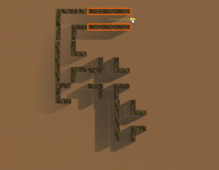
Fig. 21: Duplicate the pieces and move them on stage to build the labyrinth.
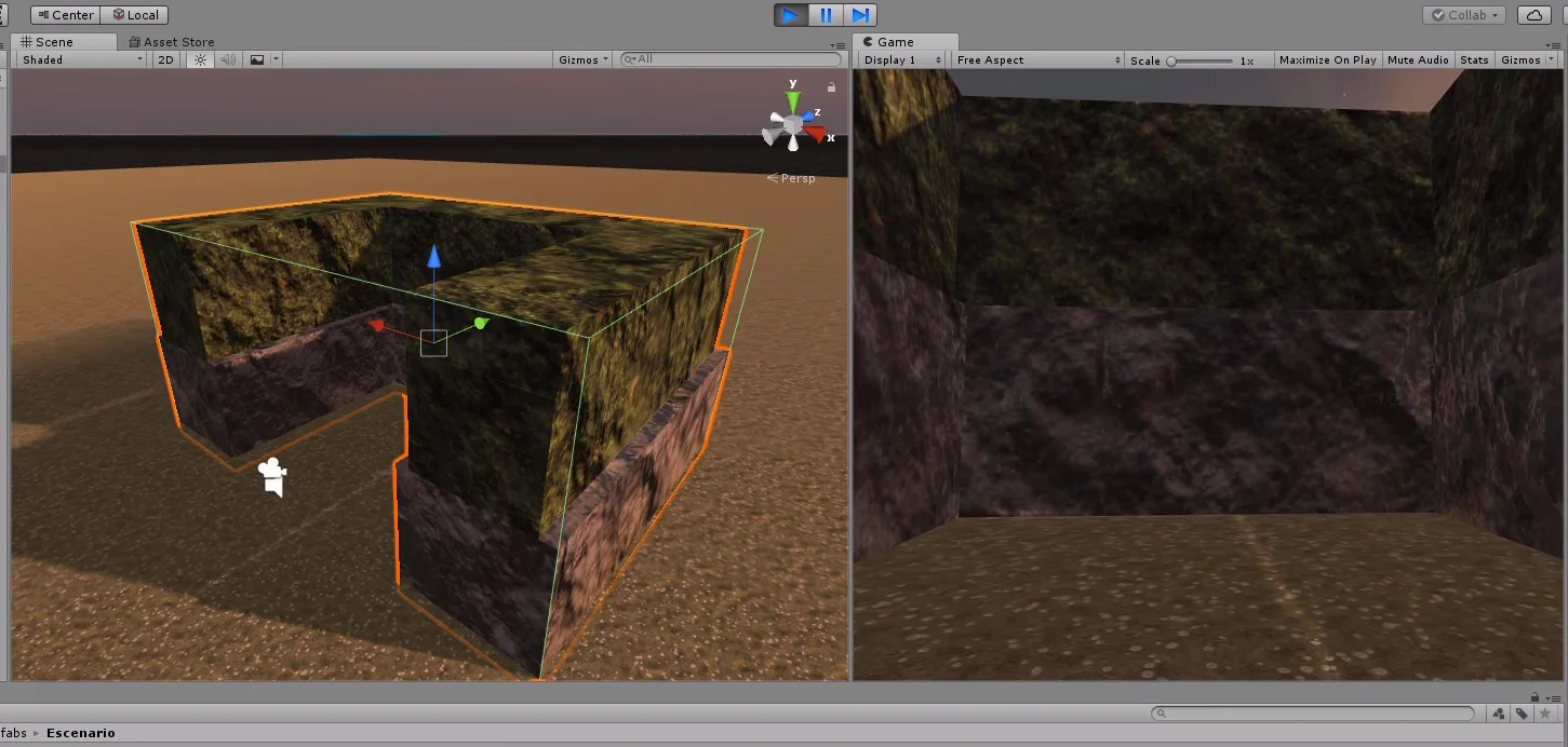
Fig. 22: Using the orthographic view and bringing the camera closer we make sure that the pieces fit together.
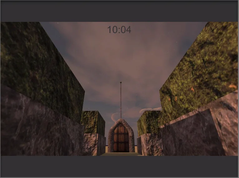
We go into game mode and go through the labyrinth to detect problems. In figure 5 you can see one of the badly placed doors.
Fig. 24: We test the scene for problems.
Fig. 25: Walking through the labyrinth we found a door that was badly positioned.
Fig. 26: We stopped the game mode to correct the problem.
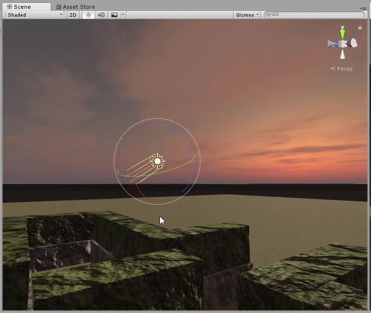
Relief modeling
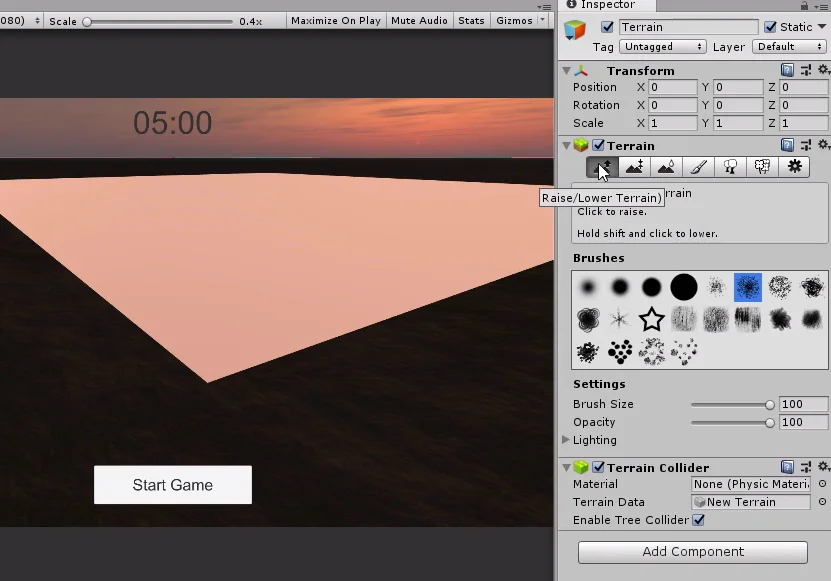
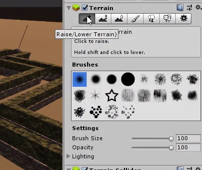
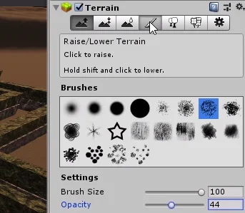
Then we’re going to start modeling the mountains. Select the GameObject Terrain from the hierarchy and in the inspector click on the first icon of the component (figure 27).
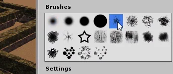
Then we select some pattern in the section “Brushes” that is observed in figure 28.
Fig. 27: Select the Raise/Lower tool in the terrain component.
Fig. 28: We choose a brush to apply the modification to the terrain.
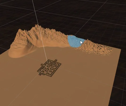
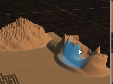
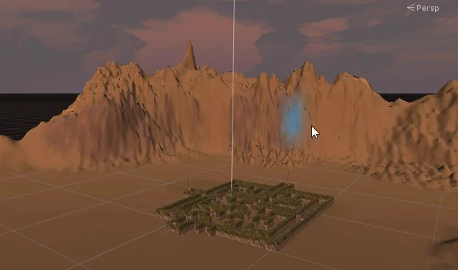
The next thing we do is paint in the editor and the terrain will gain height.
Fig. 29: We start painting regions of the terrain to produce elevations and create relief.
Another useful tool is the levelling tool (selected in figure 30).
Fig. 30: Select the ground leveling tool.
Fig. 31: We choose the height value at which we want to level the terrain.
This will allow us to establish a certain height and as we pass it over the terrain in the editor, the lower areas will begin to rise and the higher areas will descend, this is illustrated in figures 32 and 33.
Fig. 32: The regions below the level rise and those above descend.
Fig. 33: We can establish zones that will have a certain height in all its extension.
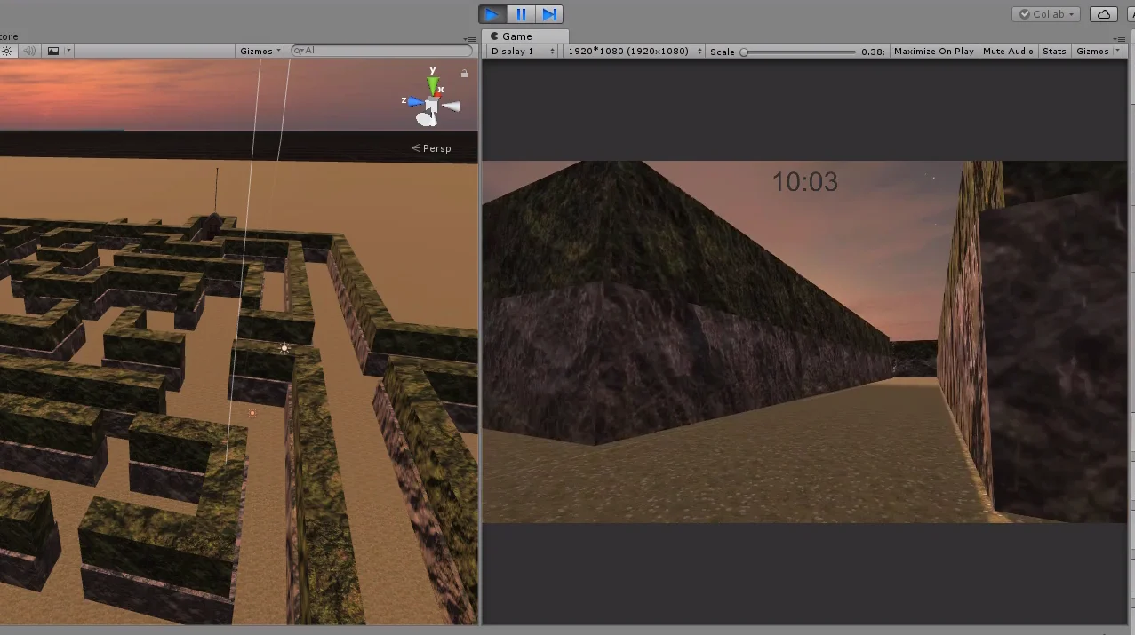
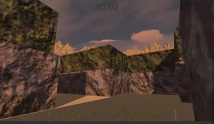
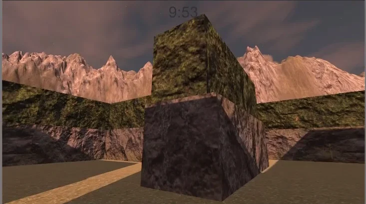
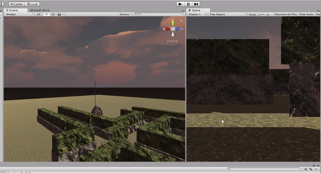
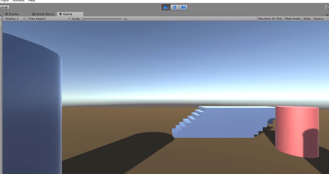
Fig. 34: We go into game mode to observe the mountainous relief from the perspective of the labyrinth.
Fig. 35: The highest part of the relief is in the opposite direction to the sun of the scene.
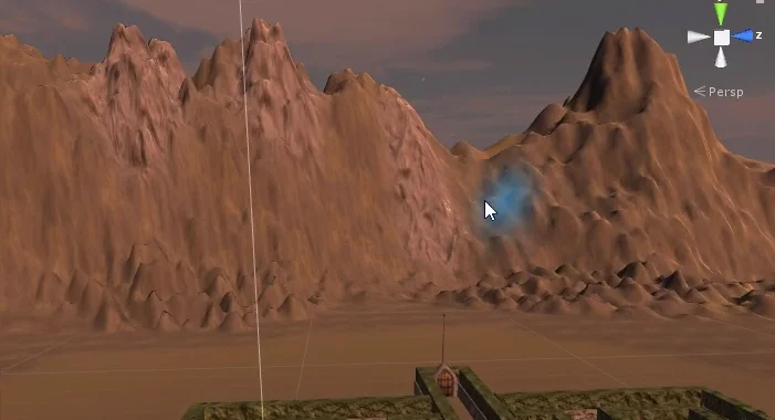
After playing with the tools for a while, I ended up with something similar to figure 36.
The most important purpose of the relief is to cover the horizon and somehow provide guidance to the player.
Fig. 36: We use the above tools until we are satisfied with the design.
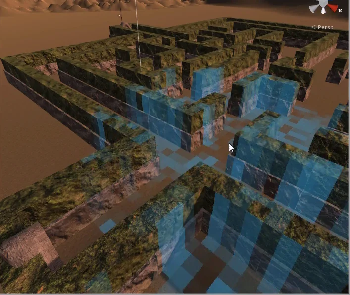
Apply textures to the terrain
In the final phase of this article on how to create a terrain in Unity we will apply the textures configured above.
Select the brush tool in the inspector, a pattern and a texture.
Fig. 37: Select the brush tool, choose the pattern and texture to apply.
Then in the editor we go around the terrain and paint.
We can alternate the textures and with this we can avoid that the ground looks monotonous with an only texture.
Fig. 38: To the base texture we apply another texture in different places to break the pattern of repetition.
The mountains will have a base of earth and then we will be applying in different parts a rock texture
Fig. 39: We give mountains a base with the ground texture.
Fig. 41: We apply the rock texture in different parts of the relief.
Fig. 40: Ground texture in the mountains.
Fig. 42: Rock texture in the mountains.
Fig. 43: Rock texture in the mountains.
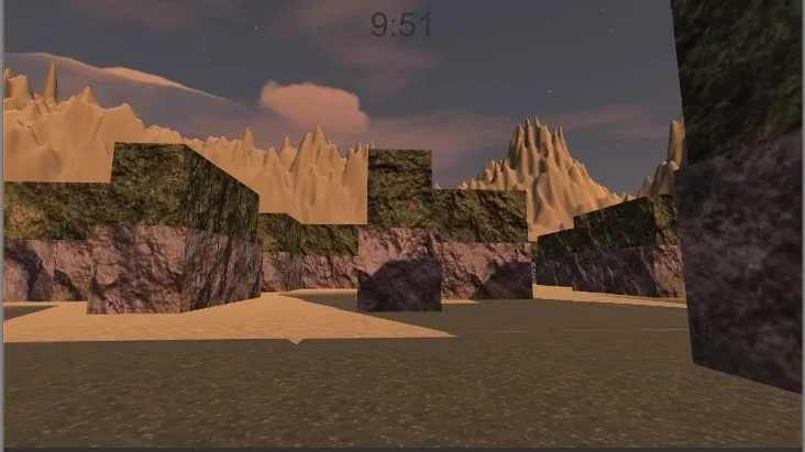
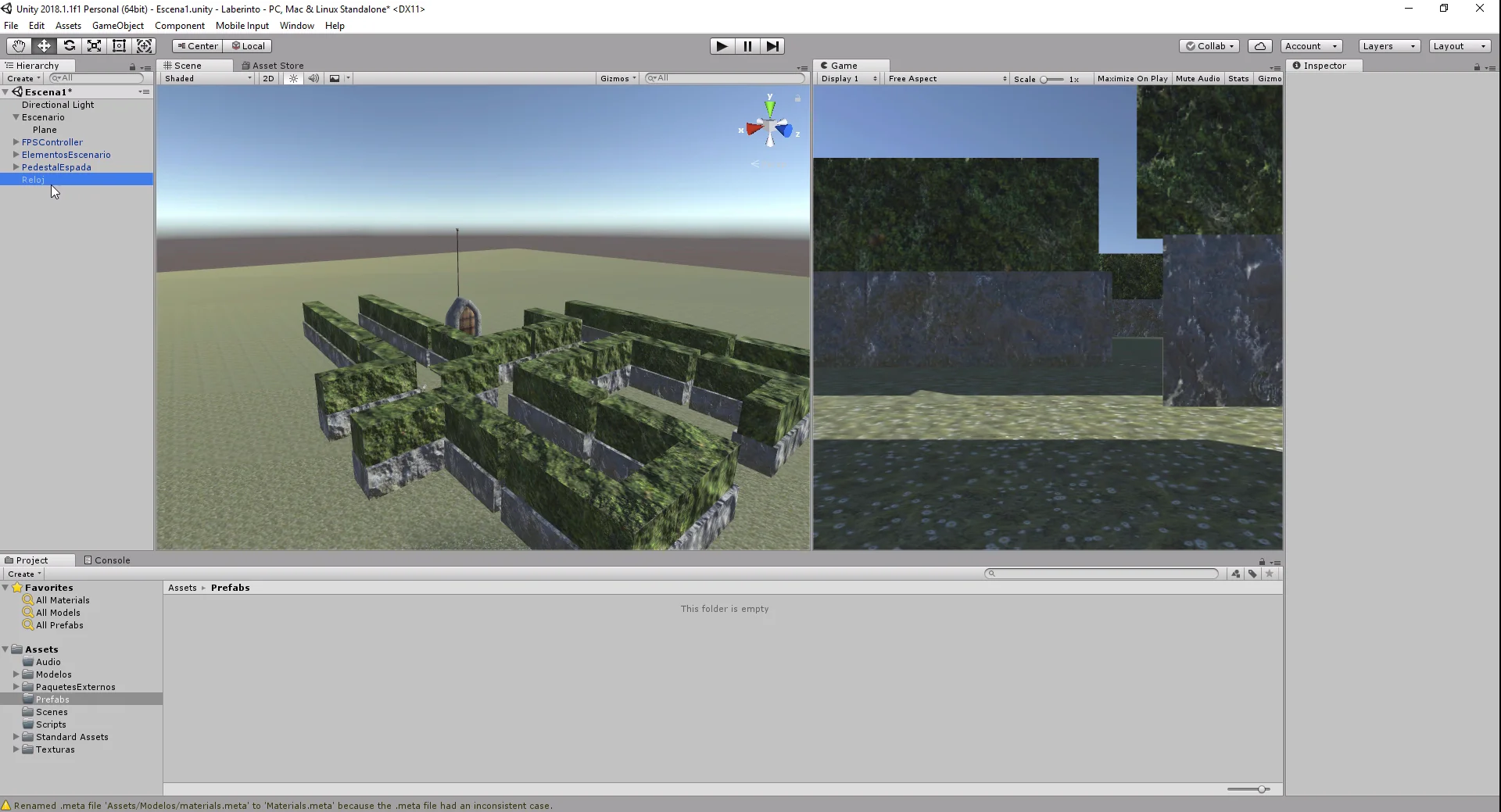
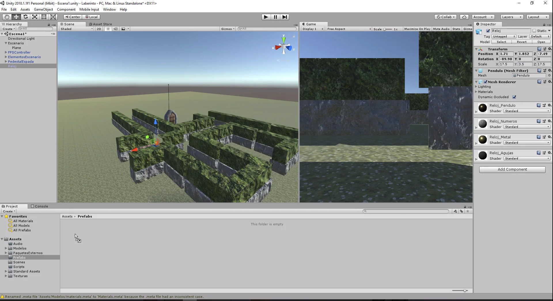
From time to time we go into game mode to see how the relief looks from inside the labyrinth.
Fig. 44: We enter the game mode to observe the results.
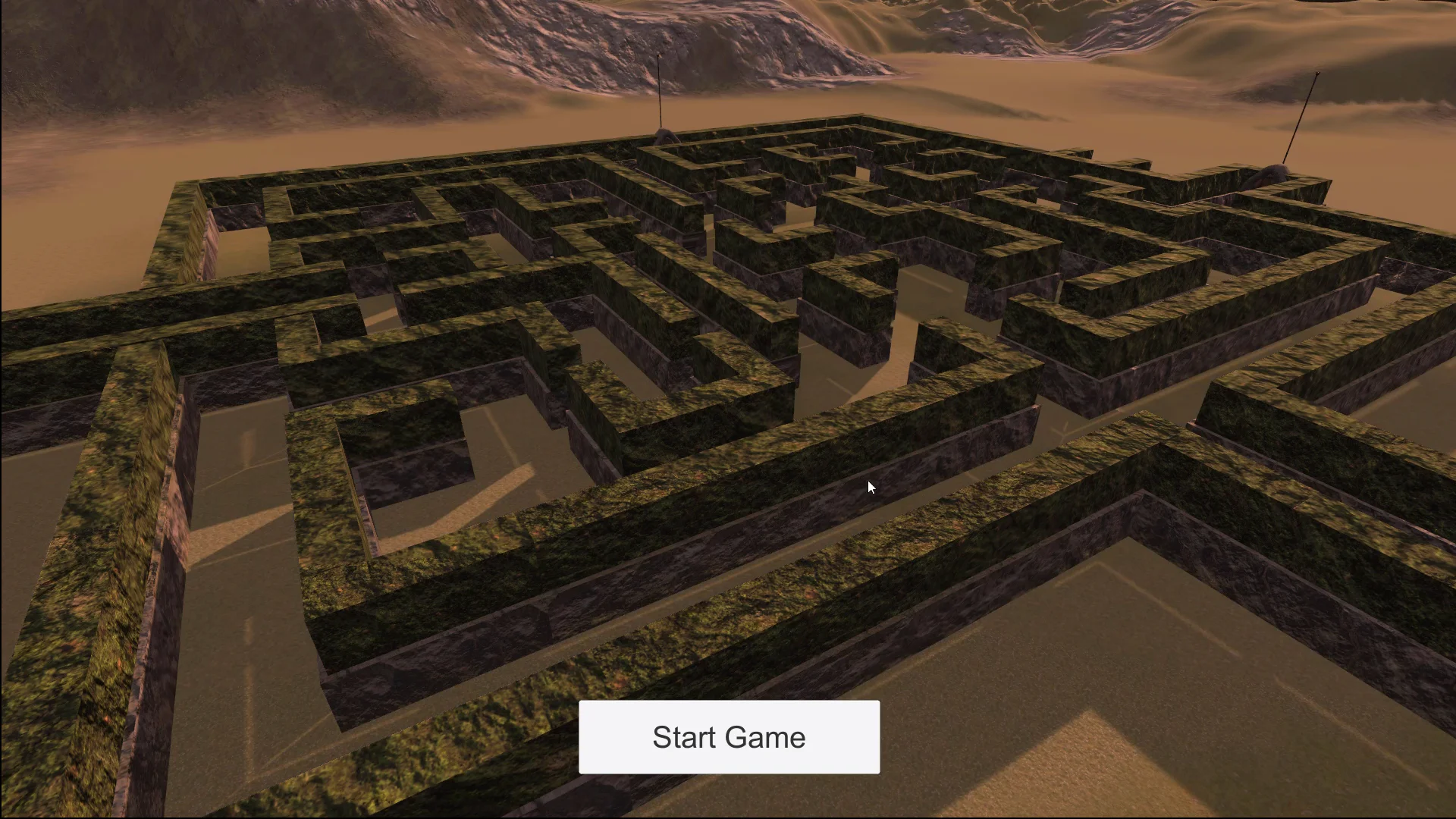
Fig. 45: Final design of the labyrinth.
Fig. 46: Final design of the mountainous relief seen from the labyrinth.
Conclusion
We’ve seen how easily we can create a piece of land in Unity using the same tools that the engine provides us. We also apply different textures to give it diversity.
The exercise proposed in this article and video is very simple, but with enough time and practice we can build a number of reliefs.
This type of land has the limitation that caverns or caves cannot be built. For that we will have to superimpose another 3D model.
In addition we have created the labyrinth using the prefabricated ones configured in previous entries. Simply by making duplicates and moving in space.
We can make both simple and complex labyrinths and assemble a level selection system if we wish. The possibilities are unlimited.
Let’s bear in mind that this project is only a prototype, in order to achieve a better graphic quality it is necessary to build better 3D models and use a greater diversity of textures and higher quality. It would be nice to add decorative elements such as rubble or trees.
Updated information about this project
This article belongs to a series that consist on making a first person game about finding objects inside a maze. It’s one of my very first series from the channel. Now I reworked this project and you can download it to import in your own Unity project. Some day I will make a new series about this project, subscribe to my channel to see all the fresh content about Blender, Unity and programming.
Follow me on itch.io and download the source code of this project
YOU CAN TRY THIS GAME HERE, IT MAY TAKE A LITTLE WHILE TO LOAD 🔻
MOVEMENT: WASD CAMERA LOOK: MOUSE
Introduction of the old article
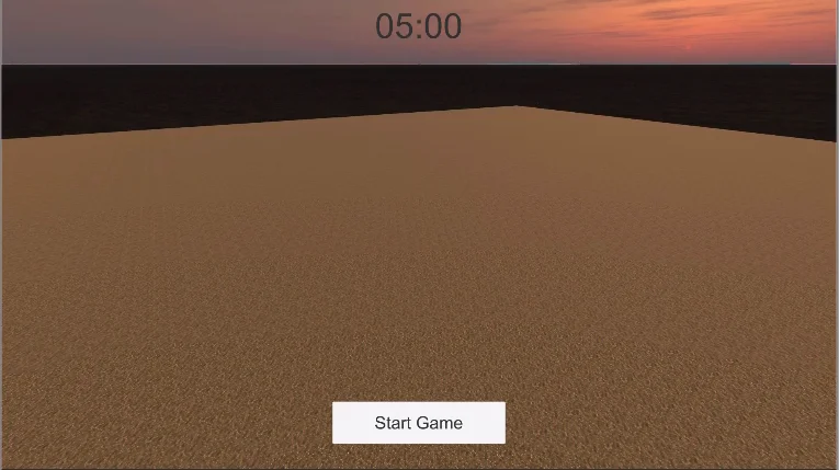
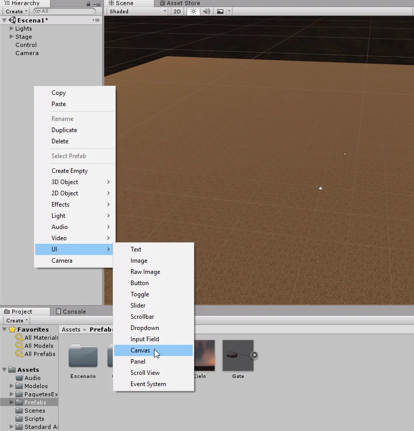
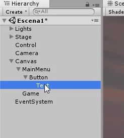
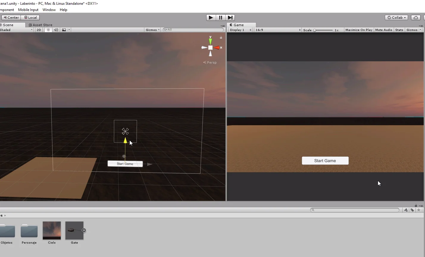
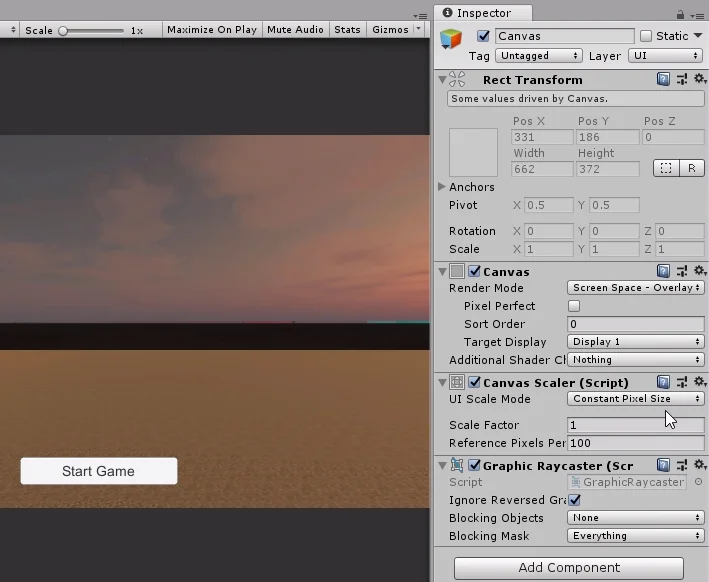
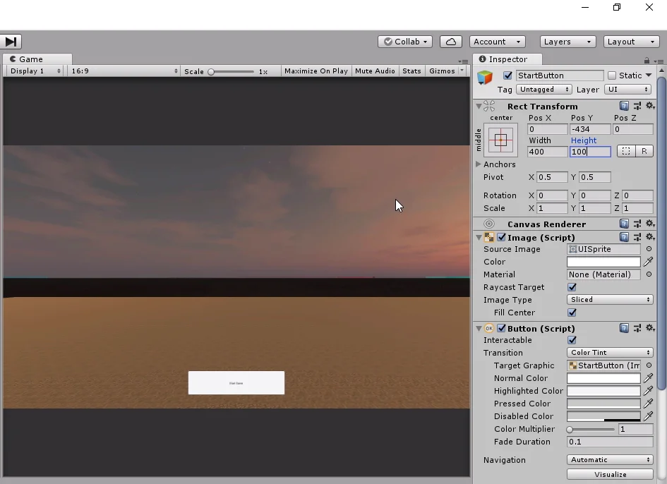
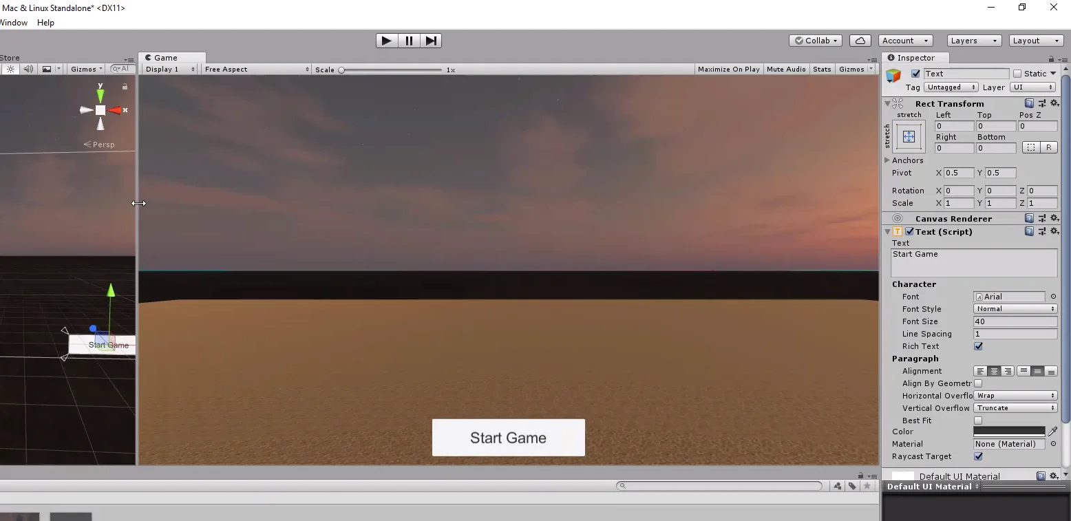
In this article we are going to see how to program a timer in C#, the operation will be counting backwards from the initial values of minutes and seconds that we indicate and in addition the Timer will be in charge of updating the information in the user interface created in the video 5 of the series of the labyrinth. Here is the article in which we created the user interface, in short we created some elements for the Canvas, which will allow the user to start playing and see information about the game.
The prototype is a first-person game in which the stage is a maze. Inside the maze, there will be a hidden object that must be found before time runs out.
Now we’re about to solve the part where time runs out. In this article we’ll create a script that is going to work as a countdown timer.
The Timer will start the countdown from a value of minutes and seconds that we will indicate in the inspector, this means that every second of clock we must update the information.
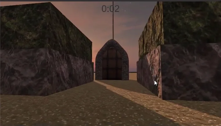
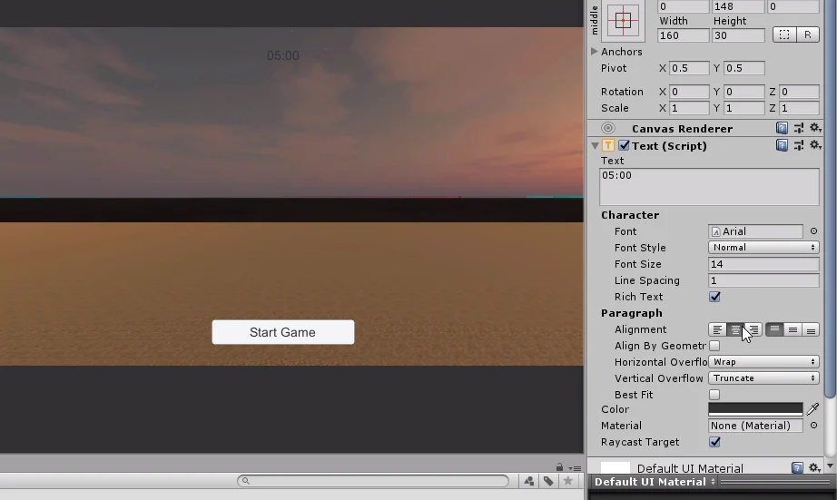
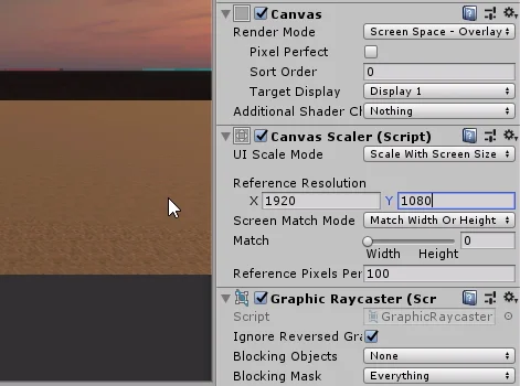
The Script Timer will also modify the value of the Canvas text element (top of figure 1).
When the time count reaches zero, the Script Timer will execute the EndGame method of the GameControl Script, this way the game will end and we will return to the main menu.
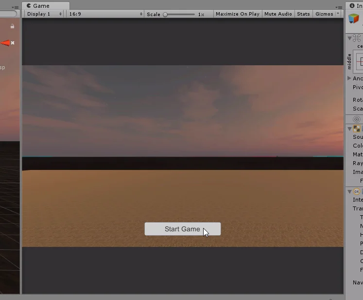
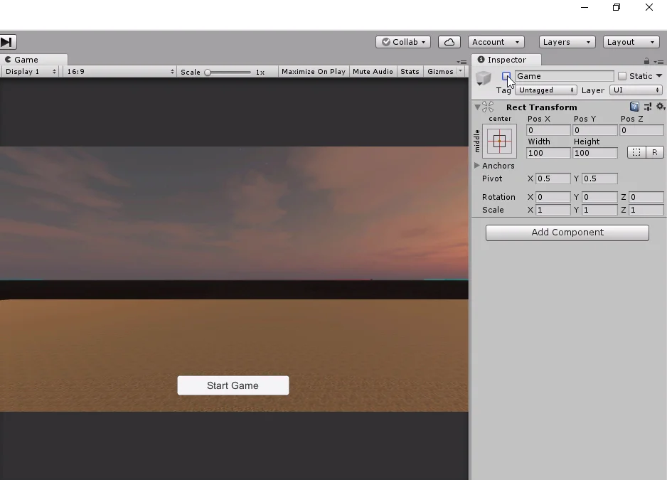
Fig. 1: The aim is to control the text at the top so that it shows the remaining time.
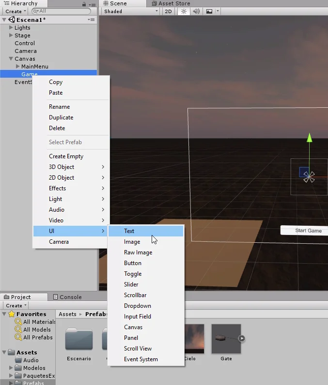
Step by Step
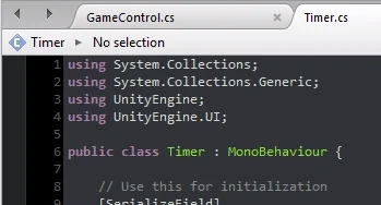
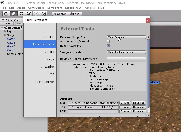
We start by creating the Timer Script and open it in the editor. In order to access to the UI components, like on-screen texts and buttons, we need to include the UnityEngine.UI namespace at the top of the script (figure 3).
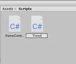
Fig. 2: A new C# Script named Timer is created.
Fig. 3: Make sure you import UnityEngine.UI to access the user interface methods.
Fields
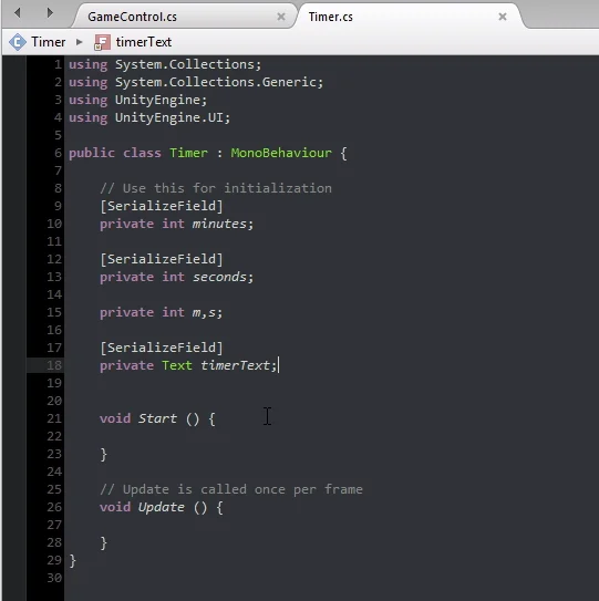
To make the countdown timer work we’ll need a couple variables.
In figure 4 you can see a “[SerializeField]” instruction above certain variables, this simply makes the variables and fields to appear in the inspector.
The two serialized integers (minutes and seconds) are the initial values of the countdown timer.
While the two private integers (m and s) will be used to keep track of time.
Fig. 4: Fields to program the countdown timer’s functionality.
We also need a Text type object to have the reference of the Text component of the Canvas.
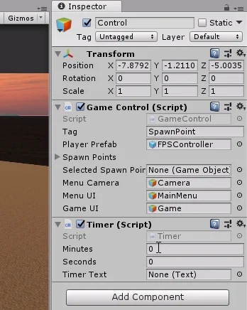
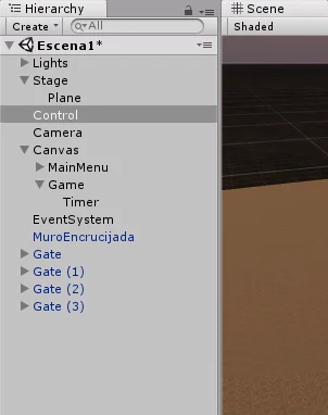
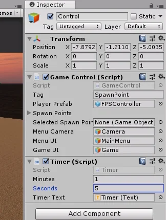
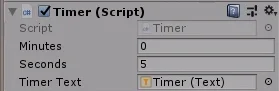
Select the “Control” object from the hierarchy and assign the Timer Script. We see in the inspector the serialized fields of the Script Timer: minutes, seconds and timerText.
Fig. 5: Assign the Script Timer to the GameObject Control hierarchy.
Fig. 6: Take the GameObject Timer and take it to the TimerText field in the previous figure.
Let’s write one minute and five seconds for the initial values of the countdown timer. Then take the Timer GameObject from the hierarchy (the one that contains the Text component, figure 6) and drag it to the timerText field.
Fig. 7: We write values to initialize the variables.
In figure 7 we can see that in the timerText field a Text type component has been recognized.
Methods to implement
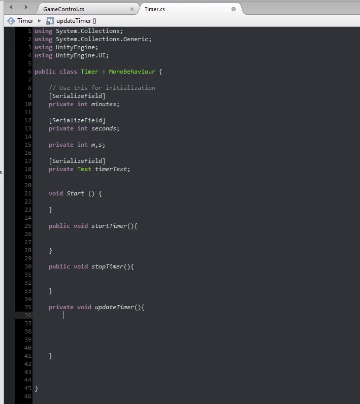
Having in mind how a Countdown timer works, some ideas of possible methods emerge. First for the Timer to start working we’ll create a method called StartTimer(). Then another method that runs at intervals of a second that is going to take care of incrementing the time value, we’ll call it UpdateTimer(). A third method to stop the Timer, that will be executed when it finishes counting, this will be StopTimer().
Fig. 8: We remove the Update method and create new methods to solve the problem.
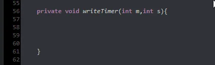
Finally, a method that modifies what is being shown in the user interface, this method will be called WriteTimer() and will take as parameters two integers for the minutes and seconds.
Fig. 9: We also added a method to write the Timer.
Note that the parameters required by this method have exactly the same name as the two integers previously defined, which are in charge of keeping track of the time.
This is done so on purpose to talk a little about contexts in programming, probably for later in another article.
Programming the functions of the countdown timer
UpdateTimer() Method
We have proposed some methods intuitively considering roughly the functioning of the Timer, now we must fill those methods with C# instructions that are the ones that will do the job.
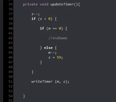
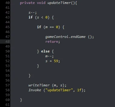
The UpdateTimer method will take care of subtracting a second, checking if the time has not run out, and modifying the minutes accordingly. Finally, it will use the WriteTimer method, passing you the values of minutes and seconds. Figure 10 shows an example of how to implement this.
Fig. 10: Instructions for the UpdateTimer method.
In the first instruction of the method we decrease by one unit the variable seconds, then we check if this variable is negative, i.e. if previously it was worth 0 and now it is worth -1.
If this happens we notice if the minutes variable is worth 0, if it is true this means that the time of the Timer is exhausted (I leave the comment //endGame in that region). If the minutes are not equal to zero, we decrease the minutes variable by one unit and make the seconds variable worth 59.
Finally we execute the WriteTimer method passing the variables m and s as parameters.
WriteTimer() Method
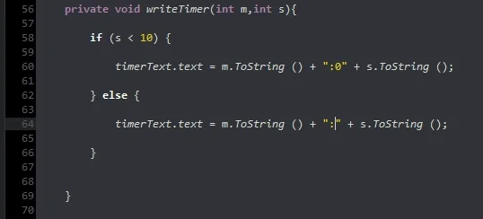
This method will take care of modifying the Text object that we had defined. Depending on whether the variable has a single digit (i.e. less than 10) or has two digits (greater than or equal to 10), we are going to execute the instructions seen in figure 11.
What is done is to concatenate a series of strings or text strings, in the case that s is less than 10, we concatenate a 0 in front of the seconds so that it conserves the format of two numbers.
There are other ways to do this such as setting a format for text strings, but in this way we take the opportunity to see how easily we can concatenate text using the sum operator.
Fig. 11: Instructions for the WriteTimer method.
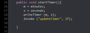
StartTimer() Method
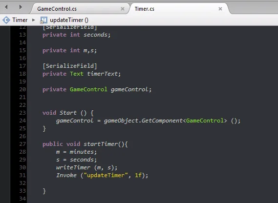
This method will perform the initialization of the Timer, that is, we take the minutes and seconds variables that appeared in the inspector with the initial values and assign them to the variables m and s that carry the count.
The method to write the values in the graphical interface is executed.
Finally we use the Invoke method, giving as parameters the string “updateTimer”, which is the name of the method and the second parameter is 1f that represents a second. This will make the updateTimer method run after one second.
Fig. 12: Instructions for the StartTimer method. Invocation of updateTimer.
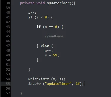
We are going to add this same instruction at the end of the updateTimer method, this way the method will invoke itself every second. This can also be done using the InvokeRepeating method instead of Invoke.
Fig. 13: The updateTimer method invokes itself every second.
Interactions between Scripts
The Timer is like a device that fulfills its function, we can configure it, put it to run and stop it. With this in mind, we are going to make the GameControl Script the one that controls the Timer, being able to start and stop it using its public methods.
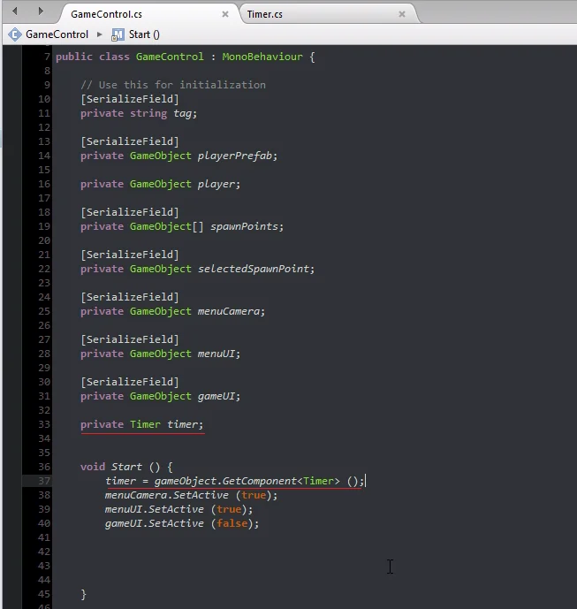
First we are going to define a Timer type object to use in the GameControl Script.
Then in the Start method we find the Timer reference that is assigned to the same GameObject Control hierarchy (hierarchy in figure 6).
Fig. 14: Add a Timer type object to the fields of the GameControl Script. Reference is found in the Start method.
In figure 14 we see underlined, the statement of this object Timer and how we find the reference in the Start method.
Now the GameControl Script has the reference of the Script Timer instance, this means that you will be able to access its methods and public fields using the dot operator.
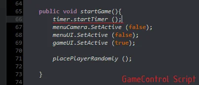
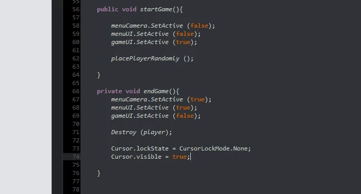
In GameControl’s StartGame method we’re going to make the Timer start working.
Fig. 15: In the startGame method we execute the Timer startTimer method.
At the same time, we also want the Timer to have some way of telling the GameControl Script that time is up, so we also need the reference to the GameControl object within the Timer Script.
In figure 16 we see the declaration of this object and how the reference is found within the Start method.
Fig. 16: Add a GameControl type object in Timer and find the reference in Start.
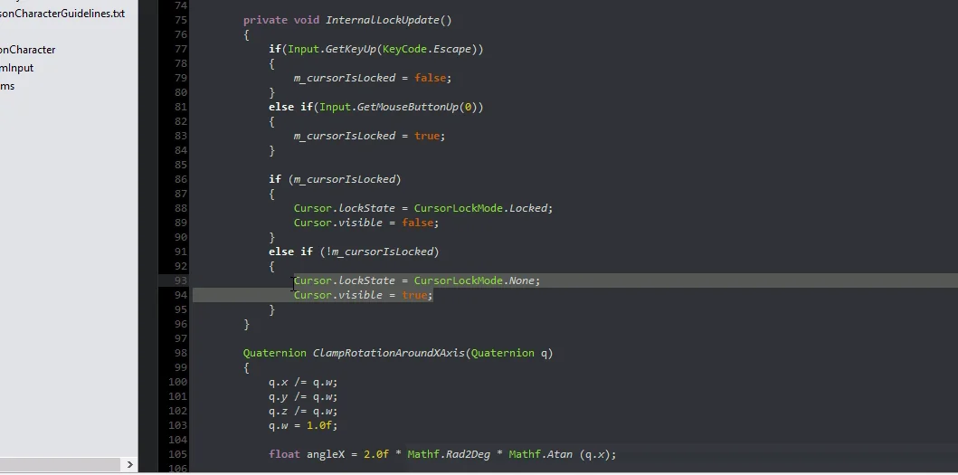
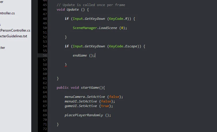
For now we are going to make that when the time runs out the game ends and we return to the main menu, that is to say the same thing that would happen if we press the Escape key. This can be done by running GameControl’s EndGame method.
In previous videos we had declared it with private visibility, which implies this method can not be executed from an external context, for example the Script Timer.
So that we can execute it from the Timer Script we change to public visibility. See figures 17 and 18.
Fig. 17: We observe that the visibility of the EndGame method is private, that’s why we can’t execute it from Timer.
Fig. 18: We change the visibility to public so that it is accessible from another context.
Now if, in the UpdateTimer region where we detected that the account reaches zero (we had left the //endGame comment), we execute the EndGame method of the GameControl Script and then the return sentence to finish the execution of the UpdateTimer method.
Fig. 19: We identify the region of the code in which time has run out and execute the EndGame method.
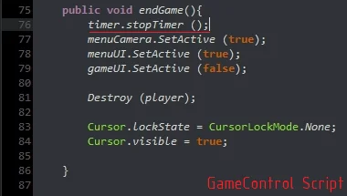
In the EndGame method of the GameControl Script we are going to stop the Timer, as can be seen in figure 20.
Why didn’t we make the UpdateTimer method stop the Timer when the count reaches zero?
It could have been done in many different ways, at the time I chose to do so bearing in mind that the Timer only serves the function of keeping track of time and warn when the time runs out, then the GameControl Script that uses the Timer decides what to do with it.
Fig. 20: In the EndGame method we execute the action to stop the Timer.
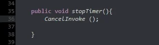
StopTimer() Method
In this method we will only cancel all invocations that may be pending, we could also reset the timer values to the initial values.
As an observation, in the code of figure 19, if the Timer reaches zero, the EndGame() method is executed and then the instruction return, which means that the program is forced to exit the current method, therefore updateTimer() will not be invoked again and the CancelInvoke() instruction would not be necessary.
But we could execute the EndGame method due to other reasons, for example pressing the Escape key or the player wins the game, in those cases it is necessary to cancel the UpdateTimer invocations.
Fig. 21: In the StopTimer method we cancel invocations that may be pending.
Final tests
I’m going to make sure it works as expected, first I’m going to set 0 minutes 5 seconds as initial values and enter the game mode.
Fig. 22: I set the initial values to quickly observe the results.
When entering the game mode the Timer starts with 5 seconds, makes the countdown and when it reaches 0 we see in figure 24 that returns to the main menu.
Fig. 23: We entered the game mode to test the operation of the countdown.
Fig. 24: When the time runs out, the result is the same as pressing the Escape key, the EndGame method is executed and we return to the main menu.
Now we verify that the format of two numbers for seconds is respected and that the minutes are correctly decremented when the seconds go from zero to 59. We start the Timer with 10 minutes 5 seconds and enter the game mode.
We observe that the format of two digits is respected for the seconds and in addition the minutes are decremented correctly. The exercise is finished.
Fig. 25: Test again with the timer in 10 minutes 5 seconds.
Fig. 26: The format of the countdown is respected.
Conclusion
We have managed to complete our Timer in C#, which serves the function of keeping track of time, displaying it in the user interface and when the time runs out notify the GameControl Script to decide what to do.
This timer could have been implemented in several different ways, the Invoke method was chosen in this case, because I considered a quite simple alternative.
We saw how easily we can modify a text component of the Canvas as long as we have its reference, so we can use this for other things like scoring, information messages, etc..
We began to introduce little by little the concept of objects, how each has a specific function and have references to other objects to make use of their methods and public parameters. This is an extremely interesting and useful topic for creating object-oriented solutions.
Updated information about this project
This article belongs to a series that consist on making a first person game about finding objects inside a maze. It’s one of my very first series from the channel. Now I reworked this project and you can download it to import in your own Unity project. Some day I will make a new series about this project, subscribe to my channel to see all the fresh content about Blender, Unity and programming.
Follow me on itch.io and download the source code of this project
YOU CAN TRY THIS GAME HERE, IT MAY TAKE A LITTLE WHILE TO LOAD 🔻
MOVEMENT: WASD CAMERA LOOK: MOUSE
Introduction of the old article
In this article we will program the logic of the user interface created in video 5 of the labyrinth series. If you did not read the previous article, in summary we created a user interface in Unity, which will have the minimum functionality for the user to interact with the game.
In the previous article we designed a simple user interface so that the user can control the fundamental aspects of our game, such as starting the game, knowing how much time he has left, etc…
At this point we are going to use the GameControl Script to manage the user interface. In the following chapters we will delegate this responsibility to a new Script.
To summarize the elements of the user interface we have two screens, one for the main menu which contains only one button that serves to start the game. The second screen is for the game and has a text element that will show the amount of time left to finish the game.
Resolution
In the GameControl Script we define three serialized GameObjects, one for the camera that is active in the main menu, another for the menu interface and another for the game interface.
The three GameObjects defined are highlighted in Figure 1.
Fig. 1: Three serialized GameObjects are defined for the camera and interface displays.
In figure 2 we can see that these new fields appear in the inspector.
Fig. 2: The three GameObjects appear in the inspector.
We take the objects created in the previous video and drag them to the fields in the inspector. These objects are the camera, the GameObject MainMenu and the GameObject Game.
Fig. 3: We take the GameObjects from the hierarchy and take them to the inspector.
Fig. 4: In the inspector we place each GameObject in its corresponding space.
StartGame and EndGame methods
We are going to define two methods, one is going to be called “startGame” and the other “endGame”. The startGame method will have the function of doing everything necessary for the game to start, i.e. setting the timer to zero, placing the character’s prefab, placing the pedestal in a random position on the stage and so on. Keep in mind that these actions will probably be defined in other methods.
In the endGame method we remove all objects from the scenario, go to the main menu and so on.
Fig. 5: The startGame and endGame methods are defined.
In the methods we are going to activate and deactivate the corresponding elements, as can be seen in figure 6.
Fig. 6: Inside each method we place the appropriate instructions.
Let’s go to the hierarchy and select the “Start” button, to observe its properties in the inspector.
Fig. 7: The start button in the hierarchy is selected.
Fig. 8: In the inspector click on the plus sign to add a function to OnClick().
In the Button component there is a field called OnClick(), let’s click on the plus sign in the lower right corner, in figure 8 the cursor is over this button.
This will allow us to run public methods within the GameObject components we assign.
In the field that appears we are going to place the GameObject Control.
Fig. 9: A space appears for placing a GameObject.
Fig. 10: Place the Control object assigned to the GameController Script.
Ahora utilizando el menú desplegable, podemos acceder a las componentes y sus métodos.
Fig. 11: With the drop-down menu you can select a method from one of the components of the Control object.
Como se trata del botón Start, estamos buscando el método StartGame que hemos definido en el Script GameControl, en la figura 12 podemos observar los atributos y métodos públicos del Script GameControl y vemos que StartGame no se encuentra entre ellos.
Fig. 12: The startGame method does not appear between the functions.
This is because we use private visibility in the definition.
To solve the problem, we changed the method to public visibility, as shown in Figure 14.
Fig. 13: We had defined the startGame method as private.
Fig. 14: We change the visibility to public.
Ahora podemos elegir que se ejecute este método cuando se haga clic en el botón Start.
Fig. 15: The startGame method now appears in the functions.
I arrange the camera a little so that the small scene of the doors is seen and I enter the game mode to test the operation of the button.
Fig. 16: Arrange the main menu camera.
Fig. 17: Enter game mode to test the button.
Bug fixing
When entering game mode, the character appears on one of the doors randomly, but for some reason the controls don’t work properly, the character drags on the floor and the camera turns in a strange direction.
Fig. 18: The game starts but there seems to be a problem with the character.
Fig. 19: The character appears on the side and cannot move.
The Debugging process can be a bit tortuous, luckily we have tools to analyze the flow of the program, discover the parts of the code that work properly, see the values of the variables and so on to detect the problem and be able to correct it.
Without going into details, because I honestly don’t remember how I discovered the bug, the problem had to do with the hierarchy structure between GameObjects and the inherited transformation of the parent GameObject.
To correct the problem in the instruction to instantiate the character, within the “placePlayerRandomly” method, change the rotation from local to global, as seen in figures 20 and 21.
Fig. 20: The placePlayerRandomly method is the one that places the character on the stage.
Fig. 21: In the instantiate instruction we change localRotation for rotation.
This corrects the problem and we can use the start button to start the game.
Fig. 22: The character now appears correctly on the stage.
Final details
When you enter the game mode, the first-person controller prefab captures the cursor, places it in the center of the screen, and hides it.
This is a problem because when we return to the main menu when the game is over we can’t click on the buttons. So the solution is to unlock the cursor and make it visible at the end of the game, i.e. in the endGame() method.
To find out how to do this let’s analyze the MouseLook Script that uses the controller in the first person. In figure 23 we can see this Script along with its route to get to it.
Fig. 23: Abrimos el Script MouseMira dentro de FirstPersonCharacter de Standard Assets.
Fatal Error
When trying to open MouseLook the editor fails and must be closed losing all unsaved changes! It is important to save at all times, the CTRL+S access is very useful.
Fig. 24: When opening the script an error occurs and all unsaved changes are lost.
On the second attempt we were able to access the script. We are looking for an instruction related to the Cursor.
We see that in lines 93 and 94 of figure 26 there are a couple of instructions that seem to be the indicated ones so we copy them.
Fig. 25: Check the MouseLook script for instructions that unlock the mouse.
Fig. 26: The two selected instructions unlock the cursor and make it visible.
Then we go to the GameControl Script and paste these instructions at the end of the endGame method that will run when the time runs out.
Fig. 27: Paste the instructions at the end of the endGame method.
End the game
We are also going to give the user the possibility to end the game whenever he wants by using the Escape key.
We do this with the GetKeyDown method of the Input class.
In the first video of Unity’s fundamental series, I explain how to read keyboard and mouse entries, plus the difference between the different methods, there is also an article about the video on this page.
Fig. 28: Execute the endGame method by pressing the escape key.
Conclusion
In the article we discuss how to program the interaction between the user interface elements and the GameControl Script.
In the case of the button the functionality is already programmed for it to execute methods of the Scripts, but we must make sure that these methods have public visibility.
Updated information about this project
This article belongs to a series that consist on making a first person game about finding objects inside a maze. It’s one of my very first series from the channel. Now I reworked this project and you can download it to import in your own Unity project. Some day I will make a new series about this project, subscribe to my channel to see all the fresh content about Blender, Unity and programming.
Follow me on itch.io and download the source code of this project
YOU CAN TRY THIS GAME HERE, IT MAY TAKE A LITTLE WHILE TO LOAD 🔻
MOVEMENT: WASD CAMERA LOOK: MOUSE
Introduction of the old article
In this article we are going to analyze in detail the video 5 of the labyrinth series, in this video we create a simple interface with the minimum functionality so that the user can interact with the game.
This article covers the design of the graphical interface, the programming of the operation is done in the following article.
The user interface of our game will allow the player to configure parameters such as resolution, volume, load and save games, start playing, see your score and so on.
In our case we will focus on making a graphical interface with the minimum functionality we need for the project, which is first a “Main Menu” where the game starts and from there we can start the game.
The second thing we need is a graphical interface that is shown while we are playing, for the moment we want to visualize the countdown.
User interface functionality
What we’re going to do is create a Canvas type GameObject that is a basic element in the GUI and then two empty GameObjects that will contain all the elements of the main menu and the game.
When the game starts the graphical interface of the main menu will be active, which will only show us a button to start the game.
Pressing the button will turn off the graphical interface of the main menu and turn on the game which shows the remaining time to complete the mission.
When the game is over, we’ll turn off the game’s graphical interface and turn on the main menu interface again.
This way we don’t need a second separate scene for the game and we can solve everything in the same scene.
Procedure
Before we start making the graphical interface we will create a prefabricated object of the door to be able to replicate easily. We took the scene as it was at the end of the previous video (figure 1) and eliminated three doors and three points of appearance.
Fig. 1: Estado de la escena al final del video anterior. Se borran tres puertas.
We take the point of appearance we have left and make it the son of the door.
Fig. 2: The spawn points are also eliminated by leaving one.
Fig. 3: Take the spawn point and make it the child of the door.
Then we take the GameObject Gate from the hierarchy and drag it to the Prefabs folder of our project, with this we create a prefab that we can place as many times as necessary in our game.
Fig. 4: Taking the GameObject from the hierarchy we create a Prefab.
Fig. 5: This allows you to replicate the GameObject as many times as you like.
We are going to create a camera that will be initially active for when we show the graphical interface of the main menu.
This camera will be turned off when the game starts so that it doesn’t conflict with the camera included in the character’s prefab.
Fig. 6: In the hierarchy we create a camera that will be active in the main menu.
User interface design
Now we begin to create the necessary elements for the graphical interface. First a Canvas where the elements will be placed.
Fig. 7: In the hierarchy we created a GameObject type Canvas for the user interface.
Como se dijo en la introducción, creamos dos Empty GameObjects para que contengan los elementos de cada pantalla.
Fig. 8: In the hierarchy we create two Empty GameObjects.
Vamos a nombrar a estos objetos “MainMenu” y “Game” para identificarlos fácilmente, como se observa en la figura 9.
Fig. 9: One empty object is called Main Menu and the other Game.
Right-click on the GameObject “Main Menu” to create a button.
Fig. 10: For the main menu we create a button to start the game.
To see our graphical interface, in the tab “Game” we will select an aspect ratio 16:9.
Fig. 11: We adjust the game view to have a 16:9 aspect ratio.
Inside the button we have like son a GameObject type text, we are going to select it to modify it in the inspector.
Fig. 12: Select the GameObject text that is the child of the button.
Type “Start Game” in the text field shown in figure 13 on the right.
Fig. 13: In the inspector we can configure the text of the button.
Using the basic tools we can position the button on the screen.
Fig. 14: Position the button on the screen.
When entering the game mode we see that the button has an animation when you press it, but of course it still does not perform any action.
Fig. 15: When testing the game, the button has an animation for the pressed one, but does nothing yet.
Let’s give the button the name “StartButton” to easily identify it in the hierarchy.
Fig. 16: Rename the button to make it easier to identify.
The next thing we do is create a text type GameObject, this time as a child of the “Game” object.
Fig. 17: We created a text type GameObject for the game interface.
In the inspector we write any value with the time format, only to visualize it on screen. Later we will modify the text using C# code.
Fig. 18: We write a time value in the text. Then we will program the operation.
In addition to writing the text we can do other actions such as center, change the size of the font, font type, color and so on.
Fig. 19: Center the text using the options in the inspector.
We choose a font size that fits the button well.
Fig. 20: We modify the size.
With the GameObject “Game” selected, at the top of the inspector we have a button that allows you to enable and disable it (figure 21), this makes it show or not in the graphical interface.
We will use this property from the C# script to program the behavior of the GUI.
Fig. 21: Using the button at the top of the inspector it is possible to disable the GameObject.
Adaptation to different screen resolutions
How to make our game look good in any screen resolution is not a minor problem.
There are several ways to approach this issue, for example we could create a different user interface for each resolution, then using a c# script we could detect what type of resolution the device has and show the appropriate graphical interface.
In this video we use a component that is assigned to the Canvas and is called “Canvas Scaler”, canvas climber.
This component will make the graphical interface bigger or smaller depending on the screen resolution. For the moment this will help us.
Fig. 22: Select the GameObject Canvas in the hierarchy and observe its parameters in the inspector.
Display the “UI Scale Mode” menu which by default is in “Constant Pixel Size” and select the “Scale With Screen Size” option.
Fig. 23: The UI Scale Mode option selects Scale With Screen Size.
Then we set a reference resolution, in my case I’m going to use 1920×1080, as shown in figure 24.
Fig. 24: Let’s set the reference resolution to 1920×1080.
We must now adjust all the elements so that they look good for that reference resolution.
Fig. 25: It is observed that we must correct the size of the elements.
Fig. 26: Using the Rect Transform component we adjust the size of the element.
Adjusting the canvas scaler is something that would have been better to do from the beginning, but in this labyrinth series we’re showing all the elements we count on to make a game in Unity, it didn’t make sense to show the canvas scaler before showing the canvas and its elements first.
Fig. 27: We adjust the font size to taste.
Once we have adjusted the elements to the new reference resolution, we can observe the behavior of the Canvas Scaler, selecting Free Aspect for the aspect ratio, using the drop-down menu we use in figure 1.
Then making the window wider or narrower we observe in figures 28 and 29 that the button becomes proportionally larger or smaller.
Fig. 28: Let’s look at the Free Aspect option for the aspect ratio. As in figure 11.
Fig. 29: Changing the width of the window shows that the button changes its size proportionally.
The last thing we do is create a new resolution for the game window. FullHD 1920×1080.
This resolution is only for viewing in the editor, it has nothing to do with the resolution that the executable game will have.
Fig. 30: We add a resolution of 1920×1080 to have reference in the game window.
Conclusion
In this article we have reviewed the key points to create a simple graphical user interface, i.e. the minimum necessary elements that the player needs to see to use the game.
The basic element of the graphical interface in Unity is the Canvas, inside the other elements will be placed.
The “Canvas Scaler” provides us with a simple solution for adapting the graphical interface to different resolutions.
As the project has not yet advanced much, the game still does not have more functionality than placing the character on the stage. Later on we’ll have to include more elements in the interface and probably create more screens.
Updated information about this project
This article belongs to a series that consist on making a first person game about finding objects inside a maze. It’s one of my very first series from the channel. Now I reworked this project and you can download it to import in your own Unity project. Some day I will make a new series about this project, subscribe to my channel to see all the fresh content about Blender, Unity and programming.
Follow me on itch.io and download the source code of this project
YOU CAN TRY THIS GAME HERE, IT MAY TAKE A LITTLE WHILE TO LOAD 🔻
MOVEMENT: WASD CAMERA LOOK: MOUSE
Introduction of the old article
In this article we analyze the video 4 of the series My First Game in Unity. In this video we created the first Script that will be in charge of placing a Prefab randomly on the stage. The Prefab that we are going to place is the first person controller FPSController of Standard Assets.
We will place the character in front of a door and as there will be several of them on the stage, we will have to make a random choice.
We began by assembling with the prefabricated a scene like the one shown in figure 1.
Fig. 1: Initial arrangement of objects in the scene.
We created an empty GameObject that we’re going to use to mark the position where the player will appear at the start of the game.
Fig. 2: A new Empty GameObject is created to assign the Script.
We are going to call this object “SpawnPoint”.
Fig. 3: The new GameObject will have the name “SpawnPoint”.
In the inspector we can choose an icon to better visualize the GameObject in the scene.
Fig. 4: We can assign an icon to the GameObject to better visualize it in the scene.Fig. 5: The GameObject is now displayed with the label selected.
We will create a new Tag to assign to this GameObject. At the top of the inspector we have a drop-down menu called Tag, clicking allows us to choose a Tag to assign or create a new one with “Add Tag”. We click on this option.
Fig. 6: Menu for assigning an existing Tag or creating a new one.
In the window that appears click on the plus sign and type the name of the Tag. It is important to note the use of capital letters.
Fig. 7: We created a new Tag called SpawnPoint.
We select again the GameObject “SpawnPoint” from the hierarchy and in the Tag menu we select the Tag “SpawnPoint” that we just created.
Fig. 8: Assign the created Tag to the GameObject “SpawnPoint”.
Creation of the first Script
Finally we are going to start programming in C#. To start we need to create a C# Script, for this we right click on a folder in the project (I suggest the Script folder we created to organize ourselves), then we go to Create > C# Script, as shown in Figure 9.
Fig. 9: Creation menu, select C# Script.
We’re going to name the file “GameControl” because it will control the fundamental aspects of our game. The file that is created can be seen in figure 10.
Fig. 10: The new script is called GameControl without spaces.
Programming usually uses a way of writing as shown in Figure 10, is known as Camel Case and consists of eliminating spaces and distinguish words using capital letters.
We use this notation for script names, variables and methods.
Before starting to program, let’s select a Scripts editor, click on Edit > Preferences.
Fig. 11: Unity preferences window, select the MonoDevelop editor.
For the series My First Game in Unity we used the script editor MonoDevelop, this editor was discontinued, that’s why in the Fundamental Series of Unity Visual Studio is used.
Fig. 12: You can choose the editor you like the most, currently the default editor is Visual Studio.
When opening the Script to edit we find some code already written.
In figure 10 the first 3 lines that begin with the word “using” are used to import libraries that will allow us to access certain functionality.
Then comes the definition of a class that bears the name we gave to the Script, in this case GameControl. It also indicates the super class, ie the class from which inherits its behavior, in this case MonoBehaviour. So all the attributes and methods of the MonoBehaviour class will be available for us to use.
The previous paragraph has several object-oriented programming concepts that do not make sense to delve into this article, because it is a fairly extensive topic. However, I believe that the mention of words such as “class”, “attributes” or “super class” may arouse curiosity and encourage the reader to investigate the subject further. At this time I do not have articles on object-oriented programming, although I wish to write them soon.
Then there are two methods defined, the Start method and the Update method. The Start method will run automatically once when the game starts and the Update method will run automatically once in each Frame in the game.
Fig. 13: View of a newly created script.
In the region that is between the definition of the class and the definition of the Start method we are going to place all the attributes of the class, that is to say all the variables and objects that we will use so that the Script fulfills its functionality. Some time ago I wrote an article about the basic types of variables that we are going to use in the tutorials.
Let’s write two lines of code, the first is “SerializeField” in square brackets, this is to tell Unity that what comes next is a field to be serialized. Without going into detail this line will make private fields (variables or objects) appear in the inspector.
The next instruction is “private string tag”, with this we are declaring a variable of type string of name “tag” with private visibility.
Visibility is also an object-oriented programming theme, used to hide attributes or methods that are not accessible from a context outside the class. Attributes or methods with public visibility are accessible from other classes.
Fig. 14: A String variable called “tag” is defined.
Asignar Script has a GameObject
For the code to be executed it is not enough to create a Script, we must assign it to at least one GameObject of the hierarchy.
GameControl will be in charge of controlling the basic aspects of the game. In principle it could be assigned to any GameObject that is present during the whole game, but for a better organization we are going to create an Empty GameObject that we will call “Control”.
Fig. 15: We created a new empty GameObject.
With the new GameObject selected, we drag the GameControl Script into the inspector to add it as a component.
Fig. 16: The new GameObject will be called Control.
Fig. 17: We can drag the GameControl Script into the hierarchy of the Control object to assign it.
Figure 18 shows that the script has been added as a component to the Empty GameObject Control.
Fig. 18: Script is now a component of the Control object.
Another way to accomplish this is by using the Add Component button and searching for the GameControl Script.
Fig. 19: Another way to assign the Script is through the Add Component button.
The reason why in figure 18 we don’t see the String “tag” that we define is because we don’t save the changes in the Script. In figure 20 you can see that in the Script tab there is a circle instead of a cross, this means that there are unsaved changes, you can easily save by pressing CTRL-S.
It is advisable to save frequently enough so that in case of possible failures we do not lose our work.
Fig. 20: The circle on the tab indicates that there are unsaved changes.
After saving the changes we see in the inspector the string “Tag”. In this field we are going to write “SpawnPoint” which is the name we gave to the tag we assigned to GameObject SpawnPoint (figures 5 to 8).
Fig. 21: The serialized string Tag appears in the inspector.
Fig. 22: We can write a value for the String.
Place character prefab randomly
The character will definitely be a GameObject, in particular the Prefab FPSController from Standard Assets. We have to tell Unity somehow which prefab we want to put on stage.
For this we are going to define a private GameObject that we will call “playerPrefab” and we will indicate it as serializable so that it appears in the inspector.
Figure 23 shows the two instructions that allow you to do this.
Fig. 23: We define a GameObject to save the Prefab of the character to instantiate.
In previous videos we had created a Prefab of the FPSController and we had placed it in Assets > Prefabs > Character. This is the Prefab that we are going to place on the stage.
Fig. 25: The prefab FPSController from Standard Assets will be our character.
We take the Prefab FPSController and drag it to the new field in the inspector, as shown in figure 24.
Fig. 24: We assign the prefab in the new space in the inspector.
It’s very important that we keep the reference of the player’s GameObject, for example to destroy it when the game is over. We are going to do this by defining a new private GameObject that we will call “player”.
In this case we will not mark this field as serializable, because it is for internal use of the GameControl Script.
Fig. 26: We define a private GameObject to save the reference of the character we place in the scene.
Then we need to know where we’re going to put the character on stage. For this we created the Empty GameObject that we call SpawnPoint (figures 2 to 5). We are going to make it the son of a door and create a Prefab of the door with the object SpawnPoint.
So each door will have its own SpawnPoint. If we have only one door in the stage, the character will appear in that place, but if we have four doors (as it will be in our case) the character will be able to appear in any of them randomly.
First we need the GameObject SpawnPoint reference, but how many? Since we don’t want to limit the functionality of this script to a fixed number of doors, we’ll simply make it automatically detect how many points of appearance there are and choose one of them randomly with the same probability.
We are going to define a vector or array of GameObjects, that is to say a structure of data that contains several ordered GameObjects, which we will be able to access with an integer value that will indicate its position in the array.
To define this array we use the word GameObject followed by square brackets, as illustrated in figure 27. As this array will contain all the points of appearance of the scenario I will call it “spawnPoints” and I will also define it as private and a Serializable field.
Fig. 27: A GameObjects Array is defined to save the reference of all the points of appearance in the scene.
In the inspector you can see what this data structure looks like. It appears as a drop-down menu that has an integer value called “Size”, which will indicate the size of the array.
As can be seen in figure 29, if we write a number in this variable, we see that there are that many GameObjects fields.
En este punto podríamos hacer que la variable Size sea igual a 4 y asignar manualmente todos los puntos de aparición, pero no queremos estar limitados a eso, queremos lograr que cuando agreguemos o quitemos una puerta, la selección del punto de aparición se haga automáticamente.
Fig. 28: Display of the Array in the inspector, we can indicate the size of the Array.
Fig. 29: When defining the size of the Array, the fields to fill in appear. We could manually place the appearance points.
We will define a new GameObject that will have the reference of the chosen point of appearance, we will call it “selectedSpawnPoint” and we will make it private and serializable to be able to observe it in the inspector.
Fig. 30: Define a GameObject to save the reference of the randomly selected point of appearance.
Programming the behaviour
Until now we have been defining the objects we will need, now we will begin to write instructions that are the ones that will make things happen in our game.
The first instruction will be placed in the Start method and will be responsible for finding all the points of appearance on the stage and save them in the “spawnPoints” array.
Figure 31 shows that the editor helps us by suggesting code as we write. If this doesn’t happen it could be for two reasons, the option “code-autocomplete” is deactivated in the configuration.
The other reason may be a bug in the editor, or that Unity is not connected to the editor. If this happens, try to solve it because not only will we not have the code suggestion but we will not have syntax analysis.
Fig. 31: As we write code the editor suggests variables or methods that start with what we write.
To find the references of the points of appearance we are going to use a method of the GameObject class that will allow us to find objects using its tag.
In figures 31 and 32 we see that there are two variants of this method, one returns a single GameObject (figure 31) and the other returns an array containing all GameObjects that have the tag we indicate (figure 32).
Notice how these two methods are only differentiated by an “s” letter.
Fig. 32: We are going to use the FindGameObjectsWithTag method of the GameObject class.
Fig. 33: The instruction in the Start method is responsible for finding all the points of appearance of the scenario and saving them in the Array spawnPoints.
In the second video of Unity’s fundamental series I analyze this way of finding GameObjects references and four other ways. I also wrote an article about that video going deeper into the information.
Figure 34 shows that when entering game mode, our array is size 1 and contains the GameObject SpawnPoint reference of the hierarchy (highlighted in yellow by Unity itself).
Fig. 34: When entering the game mode, we see that in the inspector is the reference of the point of appearance.
Let’s create some copies of this GameObject with CTRL-D and go back into game mode.
Fig. 35: Copies of the points of appearance are created.
Now we can see that the array is of size 4 and contains all the references of the GameObjects.
Fig. 36: When entering the game mode again, the Array now has four elements and all references are present.
We put a SpawnPoint in every door.
Fig. 37: We place a point of appearance on each door.
Select a random element from the array
To choose a random spawn point we need to randomly choose an element from the array. This will be done by defining an integer variable named “rand” that will be equal to a random number between 0 and the number of elements of the array minus 1.
This last part is so because in C# the first element of the array has the position 0 and the last one the position “Length-1” (size of the array minus 1).
To generate a random integer we use the Range method of the Random class and indicate two parameters, the beginning of the interval (value that is included) and the end of the interval (value that is excluded). As shown in figure 38.
Fig. 38: The second instruction generates a random integer between 0 and the number of appearance points minus 1.
Notice how the range of values for this number will automatically adjust to the number of occurrence points in the hierarchy.
The next step is to obtain the reference of the point of appearance that is in the position that defines that random integer. To access the component of an array we use the name of the array and between square brackets the whole number of the position.
The element of the array is assigned to the GameObject selectedSpawnPoint previously defined. We can see this in figure 39.
Fig. 39: The third instruction selects the point of appearance of the array.
In figures 40 and 41 we see two tests of the game in which a different point of appearance has been chosen.
Fig. 40: In this test the spawn point is D.
Fig. 41: In this test the spawn point is B.
The next step is to place the character’s prefab in the position of the selected appearance point.
For this we are going to use the Instantiate method of the MonoBehaviour class (super class of GameControl).
The fourth video in Unity’s fundamental series is about the Instantiate method, although that video is somewhat strange, the article explains in detail how the method works.
The Instantiate method has several versions, we are going to use one that requires the Prefab to instantiate, the position where it is going to be placed and the rotation it will have.
For the prefab we had defined the GameObject “playerPrefab”. While the position and rotation will be read from the GameObject “selectedSpawnPoint”.
The execution of the Instantiate method will return a GameObject which will be the reference of the created GameObject, i.e. the reference of the player. We are going to save this reference in the GameObject “player”, because we will probably use it later.
What was explained in the last three paragraphs is illustrated in the last instruction in figure 42.
Fig. 42: The fourth and final instruction places the character’s prefab at the chosen point of appearance.
As an observation, we can mention the use of the point operator to access the position and rotation attributes, which are defined in the Transform component.
In principle it is not so simple to understand, but as we acquire practice and study a little programming will become something trivial.
Figures 43 and 44 show two tests of the game in which the player appears in different positions.
Fig. 43: The character appears in the door in the upper left corner.
Fig. 44: The character appears in the door in the lower right corner.
Modularization
These four instructions that we have created place the character in one of the doors randomly.
It would be great if we had an instruction called “placeCharacterInARandomDoor” and do all the work. Then we could put a single instruction into start instead of four.
Luckily we can do exactly this by defining a new method.
Fig. 45: A private method called “placePlayerRandomly” is defined that does not require parameters and does not return parameters.
The method will be called “placePlayerRandomly”, will not require parameters, will not return data, and will be private. The definition of a method with all the enunciated characteristics is illustrated in figure 45.
In the first two videos of this series I used Spanish names, but I think it’s better to get used to using English names, as well as making it easier for me to translate.
Fig. 46: Move the four instructions to the placePlayerRandomly method.
We are going to select the four instructions that we put in the Start method, we are going to cut them and paste them in this new method, as can be seen in figure 46.
Then in the Start method we make the call to the placePlayerRandomly method, as we see in figure 47.
Fig. 47: We call placePlayerRandomly in the Start method.
Reset Scene
To easily test the random position feature, I’m going to restart the scene by pressing the R key.
For this we need to add the Namespace UnityEngine.SceneManagement, a Namespace is simply a collection of classes grouped under a name, in this case they are related to the management of scenes in Unity.
We added the Namespace in line 4 shown in figure 48.
Fig. 48: We import the SceneManagement library.
To read the keyboard we use an if sentence and the Input class. Video 1 of the Unity Fundamental Series is about reading the keyboard and mouse inputs, in the video article the information is deepened.
Inside the sentence if we execute the static method LoadScene of the class SceneManager and we pass as parameter the number zero, indicating that the scene 0 is loaded. This scene would be the first scene declared in the window Build Settings. In our case we only have one scene so it will just restart.
Fig. 49: In the Update method we read the R key and if it is pressed we load scene 0.
Final details
The last thing we’ll do is modify the rotation of the Empty GameObjects SpawnPoint, so that the blue arrow pointing in the direction opposite the door.
With the E key we select the rotation tool and keeping the SHIFT key pressed we make that the modifications of the angle are with fixed step, if I am not mistaken of 15 degrees. That way if the Y axis angle is for example 0 degrees, we can take it exactly to 90 degrees thanks to that fixed step.
Fig. 50: Rotation of the appearance points so that the character appears as if there was an entrance through the door.Fig. 51: In this case the blue axis indicates the direction in which the character is looking. In this case it must be rotated 90 degrees clockwise.
To conclude we make a compilation. In the figures 53 and 54 there are two different starts of the game, in each one the player appears in a different door.
Fig. 53: Compilation test 1.
Fig. 54: Compilation test 2.
Conclusion
In this article we saw how to create the first C# Script that will place the character in a random position on the stage.
All the attributes were analyzed to meet the objective and it was explained what each one was used for.
Modularization is a useful tool to organize our code and make it more intuitive.
Updated information about this project
This article belongs to a series that consist on making a first person game about finding objects inside a maze. It’s one of my very first series from the channel. Now I reworked this project and you can download it to import in your own Unity project. Some day I will make a new series about this project, subscribe to my channel to see all the fresh content about Blender, Unity and programming.
Follow me on itch.io and download the source code of this project
YOU CAN TRY THIS GAME HERE, IT MAY TAKE A LITTLE WHILE TO LOAD 🔻
MOVEMENT: WASD CAMERA LOOK: MOUSE
Introduction of the old article
In this article we’ll look at the different types of Colliders and how to apply them to our 3D models, as well as how they interact with the RigidBody component.
We started by clearing the scene of the GameObjects that were left in the previous video. Let’s leave the pedestal with the sword and the clock, to be able to analyze the different types of Colliders.
Fig. 1: Initial state of the scene to start working.
The sword and the pedestal are two separate objects grouped under the same father, so we can select the sword and remove it from the pedestal (figures 2 and 3).
Fig. 2: The GameObject sword is selected in the hierarchy.
Fig. 3: The GameObject sword moves away from the pedestal.
In addition we will create a cube and a sphere by right clicking on the hierarchy and using the 3D Object menu. We arrange the objects so that they look like in figure 4.
Fig. 4: Arrangement of GameObjects to analyze the different types of Colliders.
With the cube selected, we observe its properties in the inspector. By default it comes with several properties included, among them there is a Box Collider component.
Fig. 5: Viewing the inspector of a GameObject cube type.
Components can be removed by using the small gear at the top right of a component and clicking Remove Component, as shown in Figure 6.
Fig. 6: Click on the gear in the upper right corner to remove a component.
In the following figure we see that the Box Collider component has been removed.
Fig. 7: The Box Collider has been removed from the components.
We can add new components to our GameObjects by clicking on the “Add Component” button, when we do so a window is displayed with all the components and has a search bar. If we type “Collider” in the search bar we can see the different types of Collider we can add to our GameObject.
Of course there are Colliders that are more appropriate than others for a particular GameObject, this will depend on the geometry of the GameObject and the use we are going to give it.
Fig. 8: Pressing the Add Component button displays a list of all the components that can be added to the GameObject.
Let’s deactivate the MeshRenderer component of the cube to better observe the Collider, the components usually bring a small box to the left of their name to activate or deactivate them.
In figure 9 we see that the Box Collider is represented as a Cube defined by green edges. Because the GameObject is a cube, this type of Collider fits perfectly into its geometry.
Fig. 9: Switching off the Mesh Renderer component of the GameObject cube displays the Box Collider.
Now let’s select in the hierarchy the GameObject sphere and see its properties in the inspector.
This time he’s assigned a type of spherical Collider.
Fig. 10: Viewing the inspector of a sphere type GameObject.
Again we deactivate the Mesh Renderer component to observe the Collider (figure 11). Again, as it is a spherical GameObject the type of spherical Collider fits perfectly to its geometry.
Fig. 11: Turning off the Mesh Renderer component of the GameObject sphere displays the Sphere Collider.
Let’s see what happens with the sword, select it in the hierarchy and observe its properties in the inspector. Unlike the two previous GameObjects, the sword is not assigned a Collider by default, we must assign one manually as shown in Figure 8.
Fig. 12: Select the sword that was previously moved from the pedestal.
First we assign a Box Collider. In this case as shown in figure 13, we see that a box appears with the minimum volume necessary to fully contain the GameObject sword.
Fig. 13: GameObject sword with a Box Collider assigned.
Then we tried a kind of spherical Collider. As shown in Figure 14, the Collider is a sphere with the minimum radius such that the sphere completely contains the GameObject sword.
Fig. 14: GameObject sword with a Sphere Collider assigned.
Now let’s add a Mesh Collider, this type of Collider will use the geometry of the object. Figure 15 shows its properties in the inspector.
Fig. 15: A Mesh Collider component has been added to the GameObject sword.
We deactivate the Mesh Renderer to observe the Collider and what we see is that it has the exact shape of the sword, the Collider coincides with the geometric mesh of triangles.
Fig. 16: By turning off the Mesh Renderer component of the GameObject sword, we can visualize the Mesh Collider.
Of course this brings more complexity in the calculations of interactions with this type of Collider, so we have to decide if it is necessary to use it, or with a Box Collider is not enough. Everything will depend on the purpose.
Fig. 17: It is observed that the Mesh Collider has a complex geometry, which translates into more computation time.
Next we’ll select the GameObject clock in the hierarchy and apply a Mesh Collider but this time we’ll click on the “Convex” box that is seen in the properties of the Collider in Figure 18.
Fig. 18: A Mesh Collider has been added to the GameObject Clock and the Convex box has been checked.
In figure 19 we observe that now the Collider type partially respects the geometry of the object. This type of Collider also involves more calculations, but not as much as it would be in the previous case, is as if we had a low poly model of the GameObject.
It also has other advantages such as being able to use it in Trigger mode.
Fig. 19: The Mesh Collider is displayed in convex mode.
For now we saw three types of Colliders: Box Collider, Sphere Collider and Mesh Collider, the latter can be used in Convex mode, which simplifies the geometry of the Collider.
Fig. 20: Overview of Collider types.
Physical behavior of the Colliders.
The Colliders behave like barriers that can’t be crossed. In other words, if our character has a Collider and tries to go through a GameObject assigned to a Collider (such as a cube or a clock), he won’t be able to do it. Unless this Collider is in Trigger mode.
Figure 21 shows that the character is standing on the clock, the spherical Collider prevents it from falling.
Fig. 21: The player is standing on the clock. The assigned Mesh Collider prevents the player from falling through it.
Now we are going to place the sphere suspended in the air over the cube (the latter was scaled).
Fig. 22: The sphere is suspended on the hub.
With the sphere selected click on Add Component and within the Physics category select the RigidBody component.
Fig. 23: A RigidBody component is added to the sphere.
Figure 24 shows the parameters of the RigidBody component. We can assign a mass, activate or deactivate gravity and modify other parameters related to the physics of an object.
Fig. 24: Display of RigidBody component parameters in the inspector.
When entering the game mode we see that the sphere falls as if by gravity and collides with the corner of the cube (actually the collision is with the Collider).
The RigidBody component gives physical behaviour to the sphere.
Fig. 25: The ball has fallen due to the gravitational behaviour of the RigidBody component.
Add Colliders to the labyrinth pieces
We are going to place one by one all the prefabricated ones created in the previous video and configuring their Colliders so that the player can’t go through the walls.
Fig. 26: We open the folder where you can find the prefabricated products that were made in the previous video.
First the closed alley piece. We take the Prefab from the project folder and drag it to the scene or to the hierarchy. Then in the inspector click on the Add Component button and choose the Box Collider component.
Fig. 27: We place the piece “Dead End” in the scene.
We see in figure 28 that the Collider completely covers the GameObject, which will not allow us to walk inside it.
Fig. 28: A Box Collider has been assigned to the part.
Figure 29 shows that in the game mode the character can only advance to the border of the Box Collider. This type of Collider is not suitable for this piece.
Fig. 29: The player cannot enter the space between the walls because he is obstructed by the Box Collider.
We have an alternative, if we click on the button “Edit Collider” of the Box Collider (figure 30), we will be able to modify the position of its faces.
Fig. 30: Using the Edit Collider button you can edit the dimensions of the Collider.
This way we can make the Box Collider enclose a part of the object.
This way we can make the Box Collider enclose a part of the object.
Then adding more Colliders and repeating the previous process for the rest of the geometry of the object, we would be able to represent with sufficient precision the border of the object.
Fig. 32: We add two more Box Colliders and edit.
Figure 33 shows that the superposition of the three Box Colliders covers the entire geometry of the piece and allows the player to move around inside.
Fig. 33: Using three Box Colliders the frontier of the GameObject is represented.
The above works for us, but let’s eliminate all the Box Colliders and add a Mesh Collider instead, in this case the wall geometry and quite simple.
Fig. 34: When the Mesh Renderer component is deactivated, the Mesh Collider component can be seen.
Something very important when we are dealing with Prefabs is to apply the changes we are making, for that we use the Apply button located at the top of the inspector (if we have the Prefab selected).
Fig. 35: It is necessary to apply the changes that are made to a Prefab.
Figure 36 shows the model of the portal with an assigned Mesh Collider component.
Fig. 36: Mesh Collider assigned to the door. Complex geometry.
It is not justified to use a Mesh Collider for this model, taking into account the use that we are going to give it, let’s put better a Box Collider and apply the changes to the Prefab.
Fig. 37: Box Collider assigned to the door.
The same for the pedestal model, with a Box Collider we get enough.
Fig. 38: Box Collider assigned to the pedestal with the sword.
The clocks are going to be collectible objects, that is to say when the player passes over them, these will disappear and will give more time of game.
Bearing in mind the use that we are going to give them, we are going to use a spherical Collider, increasing a little the radius as it is observed in figure 39.
Fig. 39: A Sphere Collider is assigned in Trigger mode.
Then let’s activate the “Is Trigger” option of the Sphere Collider component. This will ensure that the Collider does not hinder the player and allows him to detect when he enters the spherical region.
Fig. 40: Activating the “Is Trigger” box indicates that the Collider will act as a Trigger.
Conclusion
In this article we look at different types of Colliders and what each may be appropriate for.
Everything depends on the purpose that we have for the GameObject, for example in the pieces of the labyrinth we use Mesh Collider because we need to be able to walk through the inner regions of the model. On the other hand in the clocks we use a spherical Collider because it is a piece that the character will be able to grasp.
Colliders interact with each other and are very important when RigidBody components come into play, which give GameObject physical behaviour.
Updated information about this project
This article belongs to a series that consist on making a first person game about finding objects inside a maze. It’s one of my very first series from the channel. Now I reworked this project and you can download it to import in your own Unity project. Some day I will make a new series about this project, subscribe to my channel to see all the fresh content about Blender, Unity and programming.
Follow me on itch.io and download the source code of this project
YOU CAN TRY THIS GAME HERE, IT MAY TAKE A LITTLE WHILE TO LOAD 🔻
MOVEMENT: WASD CAMERA LOOK: MOUSE
Introduction of the old article
In this article we are going to import assets, i.e. 3D models and textures, add them to the Unity engine and configure them so that they are ready to start working on stage. We are going to create GameObjects prefabricated that we can then reuse and we are going to modify the sky that comes by default, replacing it with a Skybox where we will apply the textures that were downloaded from Asset Store in the previous video.
The first thing we are going to do is to download the necessary files for the project. You can do it in the following link.
3D Models and Textures
Within these files we will find 3D models for the labyrinth walls, a pedestal, a sword and a clock. Each model has its own textures.
Fig. 1: Display of the downloaded files.
Select the folders and drag them to the appropriate folder in Unity.
I do this first by selecting the files, then clicking to drag them (a ghost icon appears indicating the amount of files being dragged) and then pressing the ALT-TAB combination to change the window, this does not make the selection lose, that’s why we can drop the files into the Unity folder.
If there are problems to do this you can minimize the Unity window or use the Unity import options.
Fig. 2: The textures have been imported and are in the project folder.
Then we do the same with 3D models. You have to take into account the folders we created in the previous video in order to organize ourselves.
Fig. 3: The textures have been imported and are in the project folder.
Modify scenario
Now let’s put all the 3D models on the stage to start shaping the labyrinth.
First we remove all the elements of the scenario except the floor. In the previous video we had placed them all as children of an Empty GameObject called Scenario.
Fig. 4: All scenario objects are selected except the floor.
The next step is to take the 3D model called ScenarioElements that we import and drag it into the scene or hierarchy. This will place all the pieces of the labyrinth on the stage.
Fig. 5: We place the 3D Scenario Elements Model that comes in the download of this page.
In the previous video we had made the floor brown. Now we are going to apply textures so we make it white again, otherwise our texture will have a brown tint.
Fig. 6: Modify the colour of the floor material so that it turns white again.
Apply textures to the floor
Now we are going to use the textures that come inside the zip that can be downloaded at the beginning of the article.
We start with the floor, inside the folder we have three textures.
The Base Color texture is used to give color to the material. Metallic determines the behavior of the material in front of light and the normal texture also determines how the light bounces off the material, but it is used to add geometric details that appear to have a high density of polygons in 3D models.
Fig. 7: Three textures corresponding to the soil together will define the material.
Place textures in the slots of the material
We add the textures in the inspector, to see the material in the inspector we have two options: we can select the material directly from the project folder or selecting a 3D model of the world that has it assigned.
Fig. 8: Display of the parameters of a standard material in the inspector.
Figure 8 shows that the textures are assigned in the slots of the material.
Albedo slot determines the color of the material, there we place the texture Base Color. The metallic texture in the slot metallic and the normal texture in the slot Normal map. For the latter we must define that texture as a normal map, there are two ways to do this, but Unity gives us the option in the same place, as shown in Figure 8 appears a sign that says that this texture is not defined as a normal map and we have a button to fix it. We click on Fix Now.
Tiling of textures
The upper left corner of Figure 8 shows a portion of the soil. Notice that the floor looks blurry unlike what it should look like (a lawn floor with daisies).
This happens because the texture is expanded to occupy the entire plane, to change this we must make it repeat more times in the geometry. This is done with the Tiling parameter of the material, in my case (because of the size of the plane) the values 100 for X and 100 for Y work.
Fig. 9: Tiling. This will cause the textures to be distributed on a larger or smaller scale within the geometry.
What is going to happen is that the same texture is made smaller and placed one after the other. In figure 10 you can see the lawn with daisies. Notice how in the lower part of the image the ground looks good, but as we move away the pattern of the texture becomes more evident, it is obvious that it is the same texture that repeats itself.
We are using a “Seamless” texture, that is to say a texture that when you put it one after the other (in the four sides) fit perfectly and you don’t notice a line of rupture. Even though the texture is very good, we can’t avoid the repetition pattern from a distance. To avoid this we have to use more textures, place objects that interrupt the pattern and so on.
Fig. 10: The floor material has a suitable mosaic size. At a distance, the texture is repeated.
Figure 10 also shows that the floor reflects a lot of light, as if it were made of glass or something similar. To correct this we decrease the Smoothness value, making the material reflect less light.
Fig. 11: Decrease of the Smoothness parameter of the material so that it reflects less light.Fig. 12: Final configuration of the material.
Extract materials from 3D models
In previous versions, when we imported a file with an FBX extension, the materials that could be defined automatically appeared along with the models. This has changed and I think it makes sense that we have to manually extract the materials, so we can have better control and avoid having many copies of the same material.
There are two ways to extract the material, at least in the version at the time of recording the video.
In this case we click on the imported model and in the inspector we go to the materials tab and click on: “Extract from prefab”.
Fig. 13: Extraction of materials from the imported file from the inspector.
A window appears to select the location of the extracted materials, if you want we can create a folder for the new materials.
Fig. 14: Selecting the place for saving the extracted materials.
The new materials appear in the selected folder.
Fig. 15: Display of the extracted materials in the project folder.
Apply textures to new 3D models
The next step is to do the same thing we did with the floor material, we are going to go material by material adding the textures to the respective slots.
There is a problem that arises when we have to do this type of tasks and is that when we select something in the hierarchy or folder of the project, the inspector shows us information about that selection. In our case it would be good that the inspector is blocked showing the material we are configuring.
For this there is the small padlock that you can see in the upper right corner of the inspector tab. Clicking on it blocks what the inspector shows and we can navigate freely through the project folders without losing sight of our material. Beware that this can also be a problem, sometimes we forget the locked inspector and we don’t know why we can’t see information about what we select.
Fig. 16: Placement of the textors in the materials. When you select a part from the hierarchy, its components appear in the inspector, including the material assigned to it.
Another alternative for this type of tasks is to modify the Unity layout for our benefit, that is to say to open more tabs of the project and to lock them so that each one shows a thing.
Figure 16 shows that one of my project windows shows the materials, the other shows the textures and the inspector shows the selected material. This makes the process of adding many textures to the materials faster.
Fig. 17: Taking advantage of the flexibility of Unity’s windows and the option of locking them to facilitate the process of configuring materials.
Creation of Prefabs
Once we have configured all the materials, the next step is to create the “Prefabs” that is to say GameObjects prefabricated that later we will be able to instantiate during the design or in time of execution of the game. For example, later on we will make the clocks appear randomly on the stage. In order to achieve that we need to have a GameObject prefabricated from which clones will be created.
Fig. 18: Process of creation of Prefabs. First we select a GameObject from the hierarchy.
To create a prefabricated GameObject we simply take it from the hierarchy and drag it to any folder in our project, as shown in figures 18 and 19.
Fig. 19: Process of creating a prefab. Second: we take the GameObject and drag it to some folder of the project.
After that the Prefab appears in the folder, as a thumbnail that shows its appearance and name. From there we can take it and drag it to the scene to create all the copies we need, as can be seen in figure 20.
Fig. 20: The prefab is in the project folder and can be reused.
We repeat this process for each individual piece of the labyrinth, pedestal and portals.
Fig. 21: Prefabs have been created for all imported models. In this way we can build the labyrinth and place the objects.
Define a new Skybox
Now let’s modify the standard sky of the scene. We will use the files downloaded from the Asset Store of the previous video, doing this was an optional step, so if you have the files no problem, we can keep moving forward.
First we create a new Material, we call it “Sky” and we select it to visualize its properties in the inspector.
Fig. 22: Modification of the Shader to define it as a six-sided Skybox.
Then we click on the Shader drop-down menu that by default has “Standard Shader” selected, instead we choose the Shader “6 Sided Skybox”. This will completely change the properties of the material in the inspector, now you see an inspector like the one in figure 23.
Fig. 23: Six-sided skybox type shader displayed on the inspector.
We will assign the textures of the Skybox package downloaded from the Asset Store to the corresponding Skybox slot.
Fig. 24: The textures downloaded in the previous video are assigned to the slots of the material in the inspector.
Then go to the menu Window > Lighting > Settings to open the lighting configuration.
Fig. 25: The lighting configuration window opens.
A window opens like the one shown in figure 26, which I place next to the inspector so that he is not floating.
Fig. 26: Display of the lighting configuration parameters.
Click on the icon of the circle with the “Skybox Material” point (on which the cursor is in figure 26) and in the window that appears we choose the Skybox that we have just configured (figure 27).
Fig. 27: Selection window for Skybox material. The previously created material is selected.
Immediately we see how the default heaven is replaced by a new sky of a cloudy sunset. With the appropriate images we can create a personalized sky for our project.
Fig. 28: The sky in the scene changes, now there is a cloudy sunset.
Adjust lighting
Figure 28 shows that the light is too pale, i.e. it does not look like the light you would see in a sunset. To correct this we select the light source in the hierarchy to see its properties in the inspector (an inspector similar to the one seen in figure 33 is observed).
In the inspector we select a color according to the tone of the sky and we adjust the intensity to taste.
Then we modify the rotation of the light source to match the position of the sun in the Skybox.
Fig. 29: The rotation of the directional light is modified to match the position of the sun in the Skybox.
At this point of the video I make a folder to place the prefabricated ones belonging to the stage and others for the objects. Again I emphasize the organization of the project.
Fig. 30: The prefabs are placed in folders with significant names to improve the organization.
Finally it occurs to me to add a second light source that points directly down and does not produce shadows, that way the scene does not look so dark.
Fig. 31: The color of the directional light has been changed to match the tone of the Skybox and duplicated to add light in the dark areas.
I select the light source from the hierarchy and press CTRL+D to duplicate it, then I orient it perpendicular to the ground.
Fig. 32: The new directional light is oriented perpendicular to the stage for general illumination.
In the inspector I adjust the parameters and in “Shadow Type” I select the option “No Shadows”, as it is observed in the figure 33. With this we finish the video 2 of the series My First Game in Unity.
Fig. 33: With the new directional light selected, in the inspector we make sure that it does not produce shadows.
Conclusion
In this video we have worked quite a bit on the aspect. We added 3D models and textures, so we learned a little more about the materials. In the case of imported 3D models, we must manually extract the materials that can bring or place new materials, this part is very connected with the 3D design of the piece, ie the materials defined in our 3D design software will appear in Unity, we may have the opportunity to delve deeper into this issue later.
We saw that we can create prefabricated GameObjects that are in the hierarchy. These prefabricated can be placed in the world easily, at the time of editing or at the time of running the game.
We modify the sky that comes by default in the scene, instead we create a Skybox type material in which we place textures to represent the six sides of the “sky box”, this behaves as if we were inside a giant cube whose horizon is very far away.
Finally, we improved the illumination of the scene a little, correcting the color and adding another light source that adds intensity but does not produce shadows.
Updated information about this project
This article belongs to a series that consist on making a first person game about finding objects inside a maze. It’s one of my very first series from the channel. Now I reworked this project and you can download it to import in your own Unity project. Some day I will make a new series about this project, subscribe to my channel to see all the fresh content about Blender, Unity and programming.
Follow me on itch.io and download the source code of this project
YOU CAN TRY THIS GAME HERE, IT MAY TAKE A LITTLE WHILE TO LOAD 🔻
MOVEMENT: WASD CAMERA LOOK: MOUSE
Introduction of the old article
This is the beginning of the Labyrinth series, in which we’ll create a simple prototype of a first-person game in which the stage will be a labyrinth, while we see all the tools that Unity has to create games.
This series is ideal for those who do not have experience with Unity as it shows a little of everything and without going into detail, the purpose is rather to observe the entire development process to get a general idea.
When you run Unity or Unity HUB, a window appears in which you can create new projects, open them and access the tutorials.
We will create a new 3D project, give it a name and choose a location on the disk. Everything else is optional. When everything is ready we create the project
We give it a name and select the 3D template.
Fig. 1: Unity startup window. Create or load a project.
The first thing we’re going to do is create a new scene. In this version of Unity, by default we create the scene “SampleScene.unity”, as seen in the header of the program in Figure 2.
To create a new scene click on File > Save Scene As…
Fig. 2: To save a new scene go to File > Save Scene As…
We give it a name and keep it. When you do it, you can see in the header the name of the new scene.
Fig. 3 Pop-up window to save the scene.
Each scene has its own design independent of the others. For example we can use one scene for the main menu and another for the game.
It’s all going to depend on how we want to structure the game.
Creating folders
It’s important to set up an organization system for our Unity game files from the beginning, because as we go along we’re creating more Scripts, importing more files and things get cluttered easily.
All project files are located in the “Project” window, inside a folder called “Assets”. This folder can be found in the directory we defined for the project.
Fig. 4: Create a new folder for the project.
As can be seen in figure 4, right-clicking displays a menu with different options, go to the “Create” option and choose “Folder”.
We create as many folders as necessary to organize ourselves, this part is personal.
Import Packages
To start making a game in Unity is not necessary to create everything from scratch, we can use existing libraries to start working on an idea. Next we’ll import Unity Packages from the Standard Assets library and the Asset Store.
Standard Assets – Unity
In the version of Unity that I had at the time of recording the video, you could import the Standard Assets packages, a library offered by Unity that has different prefabrications, effects and scripts that are useful to start with.
Right-clicking on the folder we have the option “Import Package” where we can choose a package that we have downloaded using the option “Custom Package” or we can choose a package from Standard Assets.
If you do not see all the packages as shown in Figure 5, you have the option to download them from the Asset Store, but you must have a Unity account to do so. We’ll talk about that later.
Fig. 5: Import packages from the Standard Assets library.
In this case I will import from Standard Assets the packages “Characters”, “ParticleSystems” and “Utility”.
With the package “Characters” we will be able to place in the stage a prefabricated one that has implemented a control in first person.
ParticleSystems brings some interesting effects to use, such as fire and smoke.
Utility brings some useful scripts like a frames per second (fps) counter.
Asset Store – Unity
Unity’s store contains an infinity of Assets, some of them paid and others free.
To access the shop we use the Unity Asset Store tab, if it is not open, go to Windows > Asset Store or use the direct access Ctrl+9. As shown in figure 6.
Fig. 6: Open the Assets shop from the Window.
To use the store we must log into our account (we can do it from Unity). Then using the home screen or the search bar we can explore the content.
In order to see how Asset Store is used we are going to download two packages. The first is called “SkyBox” and the second “FastMobileBloom”, we use the search bar to find them, in figures 7 and 8 you can see the miniatures of the packages.
Fig. 7: Skybox package from the assets store.Fig. 8: FastMobileBloom package from the assets store.
To add them to our project we enter the package and put “Download”, at the end of the download we have the option “Import”.
Fig. 9: When entering a package we can download and import it, read comments and more.
Project hierarchy
Within each scene all the elements of the game will be defined, that is to say a scenario, objects that are part of the world, invisible objects that serve for the logic of the game, graphical interface, etc. All these elements are known as GameObjects and will be listed in the hierarchy of our project.
As you can see in figure 10, when creating a new scene, we have two GameObjects that come by default. A camera and a directional light.
Fig. 10: Project hierarchy. By default we have a camera and a directional light.
Let’s delete the camera and start adding objects to the scenario.
By right clicking on the hierarchy we have the option to add different GameObjects, e.g. empty objects, primitives, lights, etc.
Fig. 11: Right-click on the hierarchy to create new objects.
I’m going to set up a simple stage with a floor plan and some buckets and cylinders.
Fig. 12: Plan created from the hierarchy.
As we add more objects to the scenario the hierarchy grows. It’s also recommended to have a good organization from the beginning, placing appropriate names and using Empty GameObjects to group the objects.
Fig. 13: Adding objects to the world.
Note figures 14 and 15. In the first one you can see that both cylinders are contained by the cube, as they are slightly to the right and the cube has an arrow to unfold and collapse the contents. In figure 15, on the other hand, it is observed that they are at the same level, so to speak.
Fig. 14: The cube is the father of the cylinders.Fig. 15: The hub and cylinders are on the same hierarchical level.
This represents the kinship that exists between GameObjects. In figure 14 it is said that the cube is the father GameObject and both cylinders are children. This implies that the cylinders are going to be affected by certain changes that apply to the parent. For example if we deactivate the cube, both cylinders will also be deactivated.
The same applies to the transformation component, for example. The position of the cylinders is measured with respect to their parent, so if we move the parent, the cylinders move together.
Materials
To apply colors and textures on the objects of the world the materials are used. Let’s create some to see how they work. Right click on a project folder then Create > Material, as shown in figure 16.
Fig. 16: Materials creation process.
The material is visualized as a sphere in which are applied the properties of the material we must assign it a name, as always maintain the order from the first moment benefits us in the long term.
Fig. 17: Display of the materials in the project window.
The materials have several parameters that define it, in our case we will simply modify the color by clicking on the box to the right of “Albedo”. When doing so, a color palette appears where we can choose the color or write its hexadecimal code.
Fig. 18: Display of material properties in the inspector.
To apply a material we simply drag it over the desired object.
Fig. 19: A material has been applied to the plane.
Lighting
Let’s select the directional light from the hierarchy or in the scene window.
Fig. 20: Materials have been applied to all objects in the scene.
Directional light is a source of light such as the sun, i.e. situated in infinity and sending all its parallel rays. For this reason moving the source or making it larger does not affect the illumination of the scene, but changing the rotation if it does. We see it in the direction of the shadows.
Fig. 21: Rotation of the directional light, the shadows are projected in another direction if we compare with figure 20.
Create a ladder with primitives
Let’s do this little exercise to see the elements of Unity’s toolbar, particularly the tools that will allow us to modify the Transform component of GameObjects. We started by creating a cube in the hierarchy.
Fig. 22: Unity’s basic toolbar.
The tools move, rotate and scale are shown in figure 22 in positions 2, 3 and 4 respectively and are quickly accessed using the “W”, “E” and “R” keys (respectively).
If we press the R key with the cube selected, we can scale it using the “Gizmo” of the three axes, as shown in figure 23.
Fig. 23: Scaling a GameObject in one direction.
We scale it in two directions to give it the appearance of a step.
Fig. 24: Scaling a GameObject in one direction.
We apply a material to it and with the W key we can place the step on the stage.
Fig. 25: Positioning of the object in the scene.
We can easily duplicate the object using the shortcut CTRL+D and with the W key raise it a little and move it backwards.
Fig. 26: Duplication of a GameObject.
We can repeat this process with several selected steps.
Fig. 27: Duplication of a set of GameObjects.
Let’s create an Empty GameObject and call it “Scenario”.
Fig. 28: Creating an Empty GameObject to organize elements.Fig. 29: The Empty GameObject is given the name Scenario.
Then we select all the objects and drag them to this new object to group them. In this way we can collapse the whole content and the hierarchy is more orderly, as shown in figure 30.
Fig. 30: All GameObjects on the stage are dragged into the Empty GameObject and the content collapses.
First-Person Controller
The reason why we previously removed the camera is because we are going to place the prefabricated “FPSController” from Standard Assets on the scene and it already has a built-in camera. This prefab is located in the directory Standard Assets > Characters > FirstPersonCharacter > Prefabs.
Fig. 31: Prefab FPSController of the Standard Assets Characters package.
We take it to the scene and put it where we like.
Fig. 32: The FPSController prefab is placed in the scene.
Bugs
We are already able to do some tests, in the top center we have three buttons.
The Play button is used to start running the game. The second button pauses the game but does not end it. The third button is used to advance a single frame in the game.
Pressing the Play button displays an error sign saying that all errors must be fixed before you can enter game mode.
Fig. 33: When trying to enter game mode an error message appears.
This is a problem that we are going to encounter very often, especially at the beginning and it is usually very frustrating, even more so if we are learning to program.
To get information about what is happening we have the “Console” window. If it is not open, you can find it in the “Window” menu.
Fig. 34: Several warnings with a yellow sign are displayed on the console.
In figure 34 we see a large number of warnings but this does not affect the operation of the game, are suggestions for optimizing the code, warnings for use of obsolete code and so on. If only we had warnings we could enter the game mode without problem.
Figure 35 is a screenshot after clicking the “Clear” button, this clears the warnings and lets you see the errors that cannot be overlooked in order to enter the game mode. These are shown with a Red sign.
Fig. 35: The console displays an error message with a red sign.
There is not much information about the error but it is enough for us to understand that there is a file that is not found. If we look at the address we see that it is related to the Standard Assets package and we see that its address begins with “Assets > Standard Assets > …”. In the video we made a folder called “External Packages” and inside it we put the Standard Assets package.
Everything seems to indicate that there is some process that is looking for Standard Assets files but inside the Assets folder, not the External Packages folder, so I move the Standard Assets folder to the Assets folder and the error is fixed. Now if we are able to enter the game mode.
Fig. 36: The Standard Assets package is taken to the Assets folder of the project.
Testing the game at Unity
The prefab FPS Controller works like a standard first-person game. Move forward, backward, sideways with WASD keys or arrows. Jump with space bar, with Shift you can run. With the mouse you can control the view and it has the sound of steps. It’s a good starting point to start forming an idea.
Fig. 37: After correcting the errors, the game mode can be entered.
Build the project
Now we will generate a standalone version of the project, ie a set of folders and executable file that can run on our operating system without having the Unity engine open.
Go to the File tab and click on Build Settings to configure the compilation parameters.
Fig. 38: To make a compilation click on File > Build Settings.
We get the window illustrated in figure 39, there we can select the target platform.
If you look at the top is where the game scenes are listed. At that time we don’t have any scenes added to the compilation.
Fig. 39: Window with compilation parameters. No scenes have been added.
By clicking on the Add Open Scenes button we are going to add the scene we were working on throughout the video. As you can see in figure 40.
Fig. 40: Compilation window. The scene in which we work has been added.
Now all that’s left is to click on Build And Run and choose the folder where to place the generated files. At the end of the compilation process the game runs and a window appears in which we can select the resolution and quality. Press the Play! button and the game starts.
Fig. 41: Game start window. You can choose the resolution and quality.
Conclusion
In this article we saw the first steps in starting a game at Unity. We put emphasis on organization, which will benefit us in the long run in development.
We saw the scenes of Unity, each scene is a world apart and contains a certain amount of elements or GameObjects that are listed in the hierarchy of the project.
We import files from both the Standard Assets library and the Asset Store. At the beginning the most important thing is to try to give form to the ideas that we have, for this the assets of the bookstores facilitate the things to us.
We saw something about the parentship that exists between GameObjects and how changes applied to a parent object also impact their child objects.
We create materials that give color and texture to objects.
The directional light source serves us to illuminate a scene as the sun would, the shadows will be projected according to the rotation that this light source has.
We made a simple ladder using the primitives that can be created with Unity and applying transformations to them, that is to say changes of scale, rotation and position.
We place the Standard Assets prefabricated “FPSController” which is a first person control. Quickly we already have a character that can go around the stage, run and jump.
In the process there were bugs that we had to fix in order to get into game mode. Debugging errors is a difficult task when we start programming, but with practice we make fewer mistakes and it’s easier to correct them.
Finally we made an executable compilation from the operating system. There are a lot of platforms to which we can export our game in Unity. In principle we are going to export to Windows and Android.
This website uses cookies to improve your experience. We'll assume you're ok with this, but you can opt-out if you wish. Cookie settingsACCEPT
Privacy & Cookies Policy
Privacy Overview
This website uses cookies to improve your experience while you navigate through the website. Out of these cookies, the cookies that are categorized as necessary are stored on your browser as they are as essential for the working of basic functionalities of the website. We also use third-party cookies that help us analyze and understand how you use this website. These cookies will be stored in your browser only with your consent. You also have the option to opt-out of these cookies. But opting out of some of these cookies may have an effect on your browsing experience.
Necessary cookies are absolutely essential for the website to function properly. This category only includes cookies that ensures basic functionalities and security features of the website. These cookies do not store any personal information.


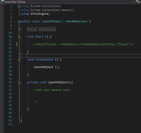

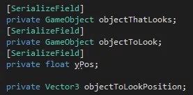

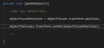


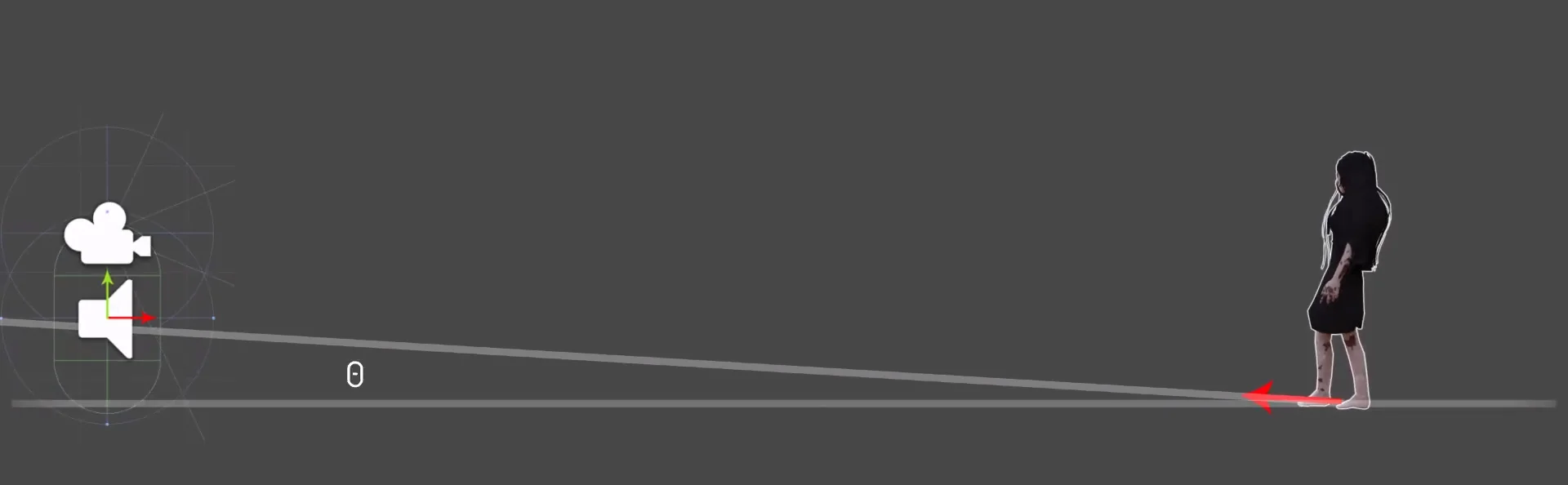


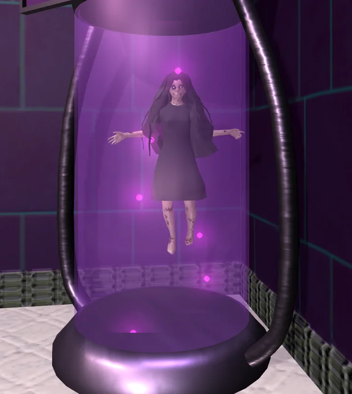


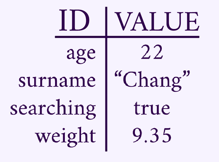
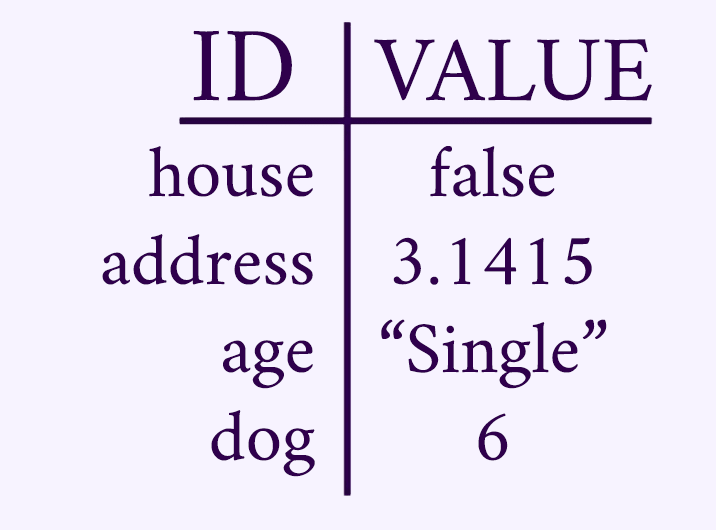

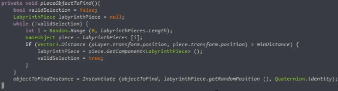

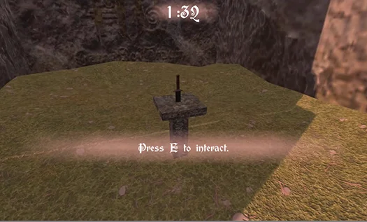

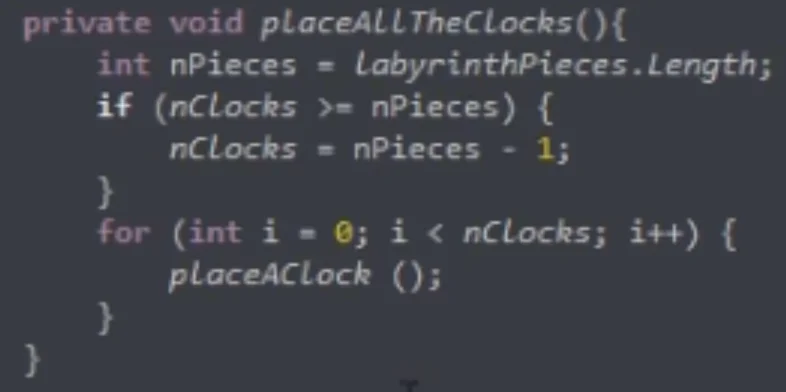

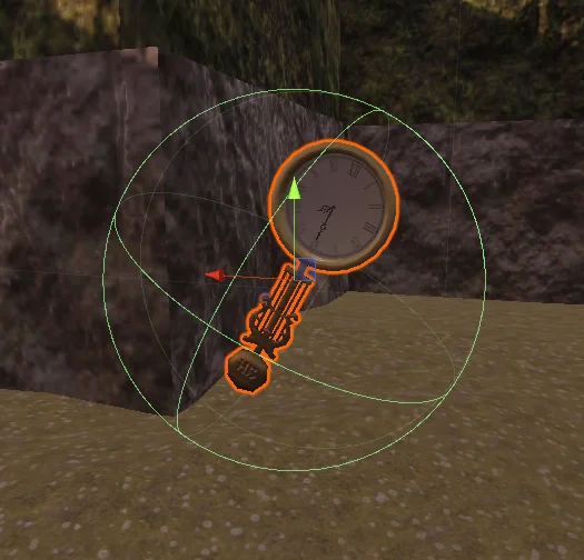

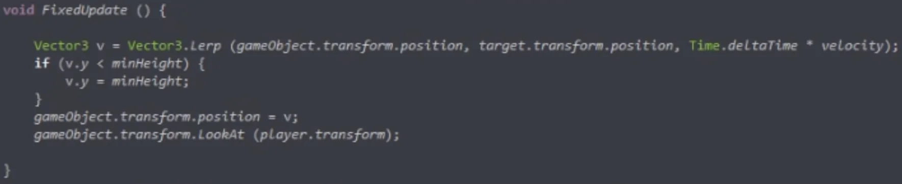

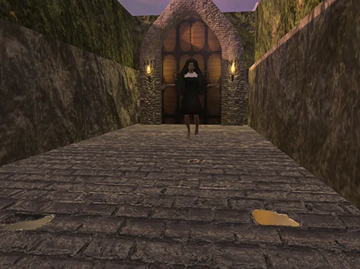

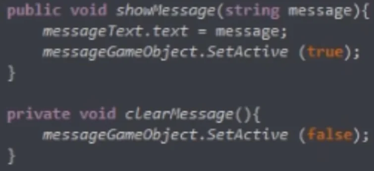

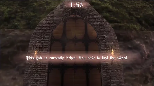


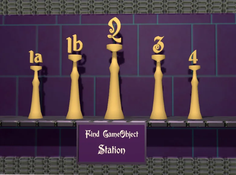

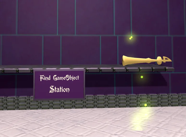


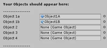

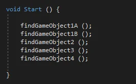

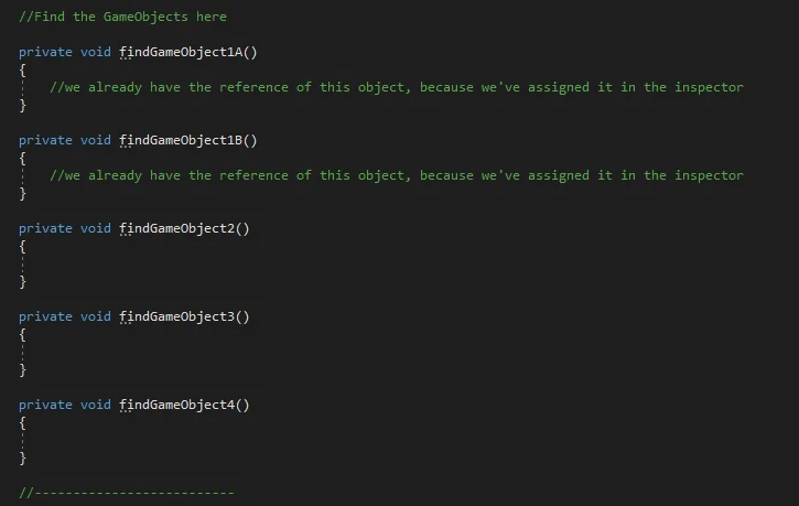


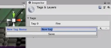


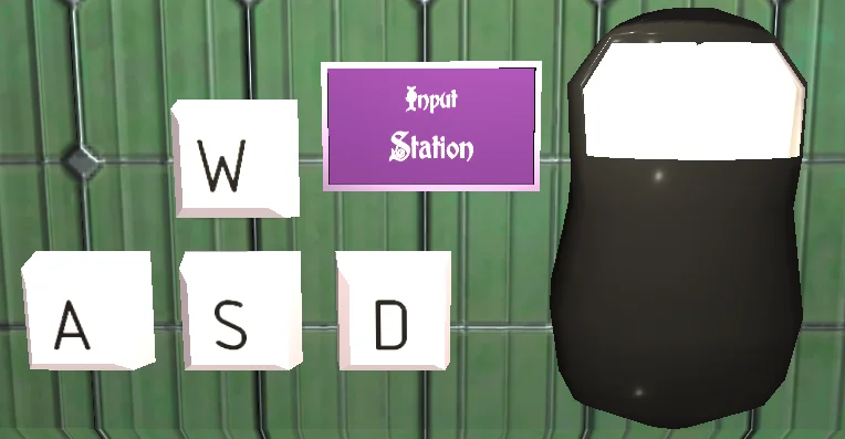

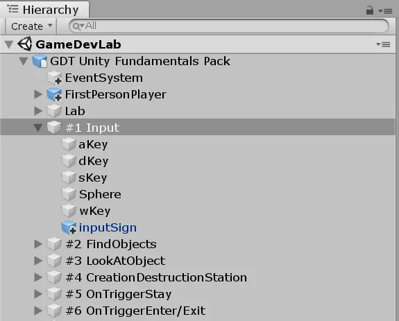

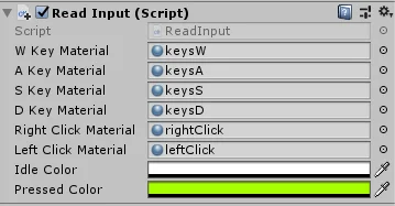

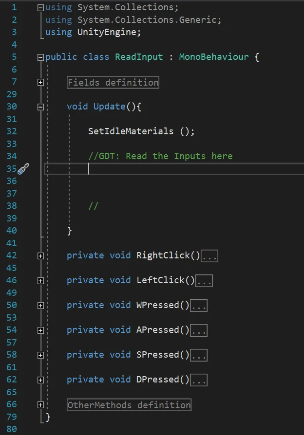

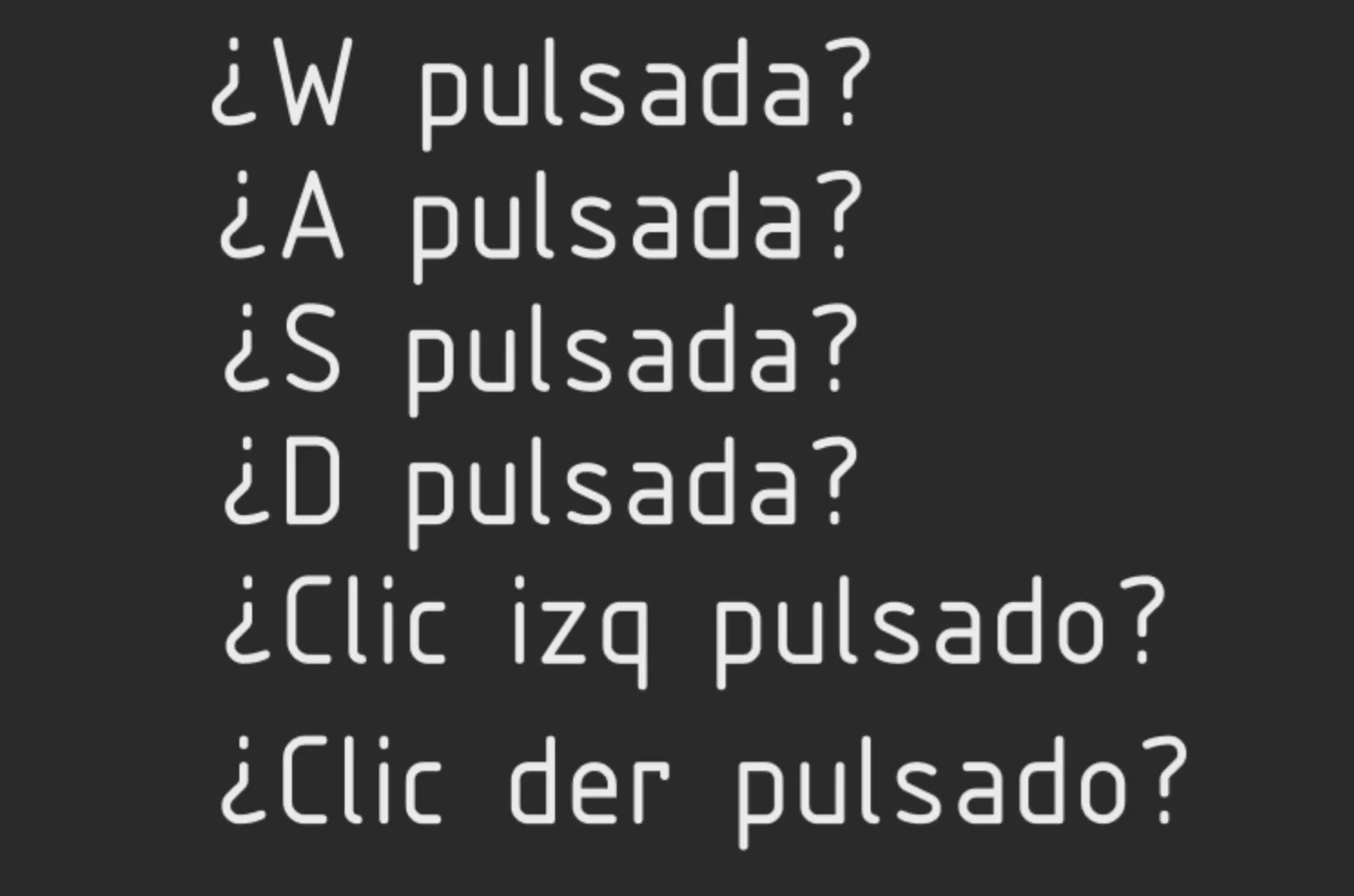

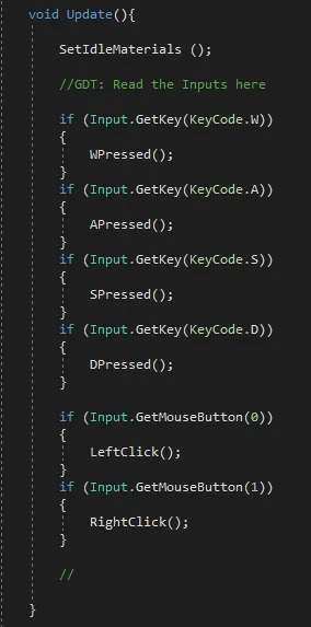

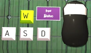

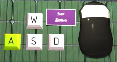

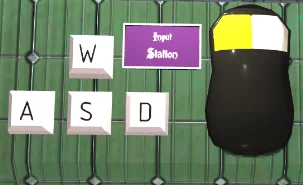

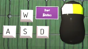

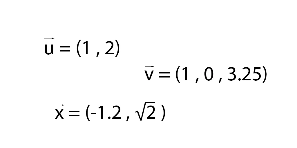
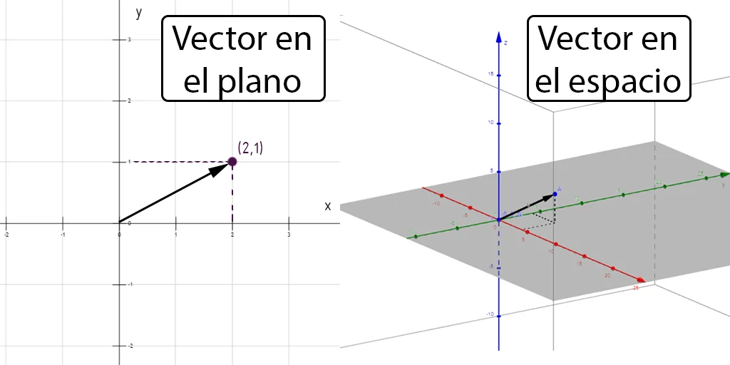

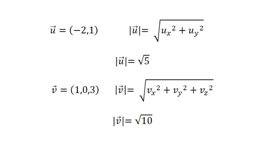

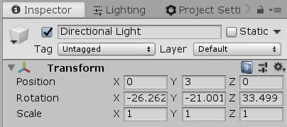

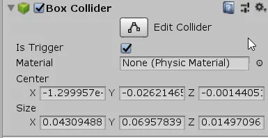

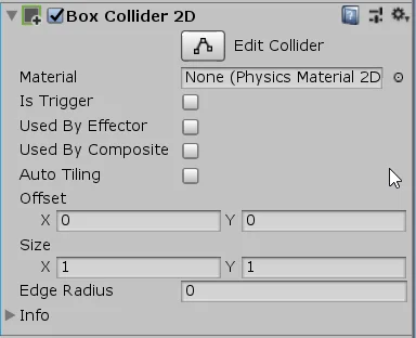
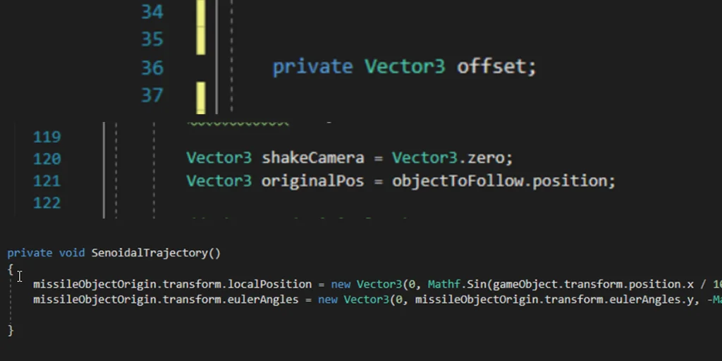

![[UNITY 3D] Randomness #3. Placing objects on the stage RANDOMLY](https://i.ytimg.com/vi/jbx3NXfzL30/hqdefault.jpg)


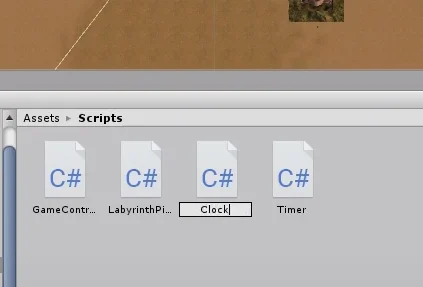

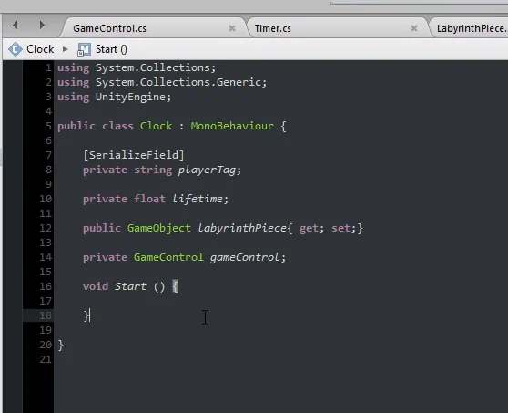

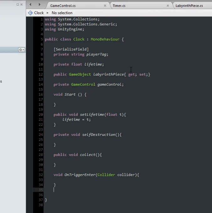

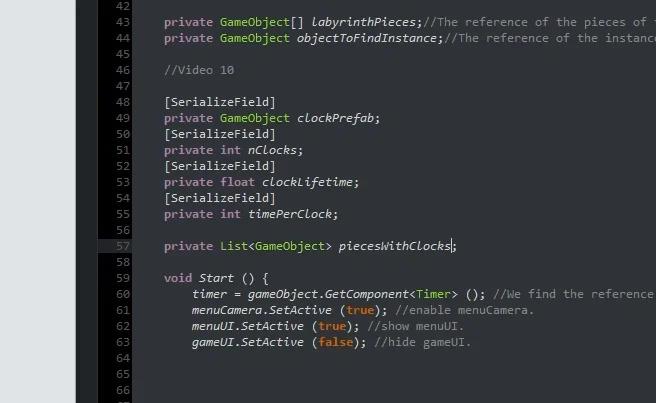

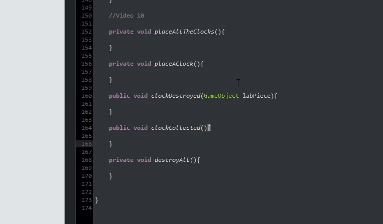

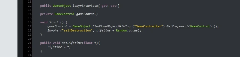

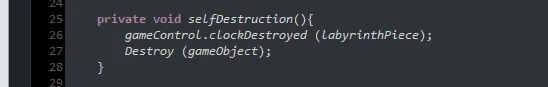

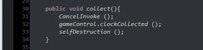

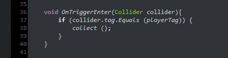

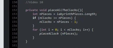

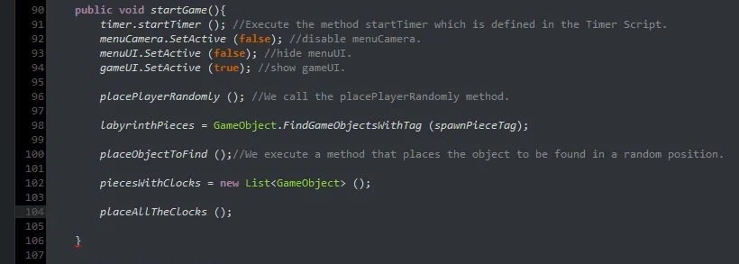

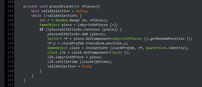


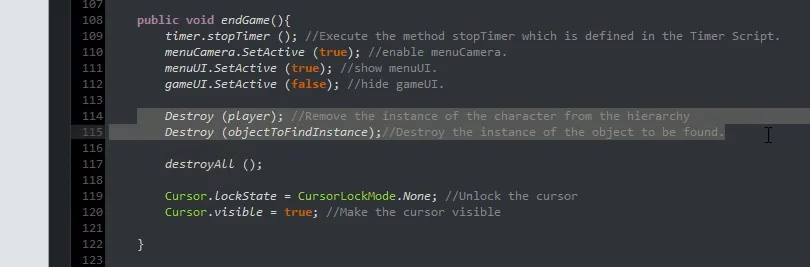

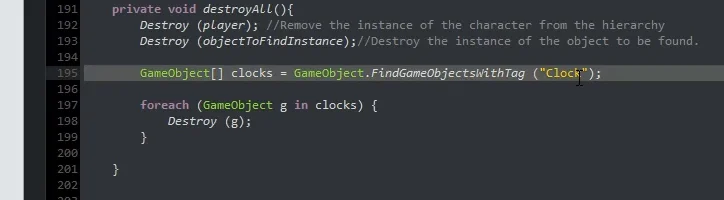


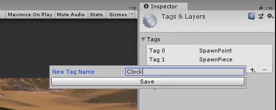

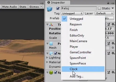

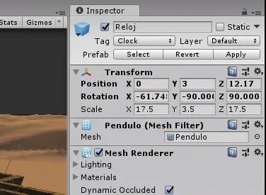


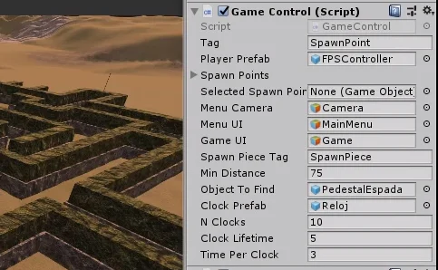


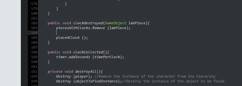


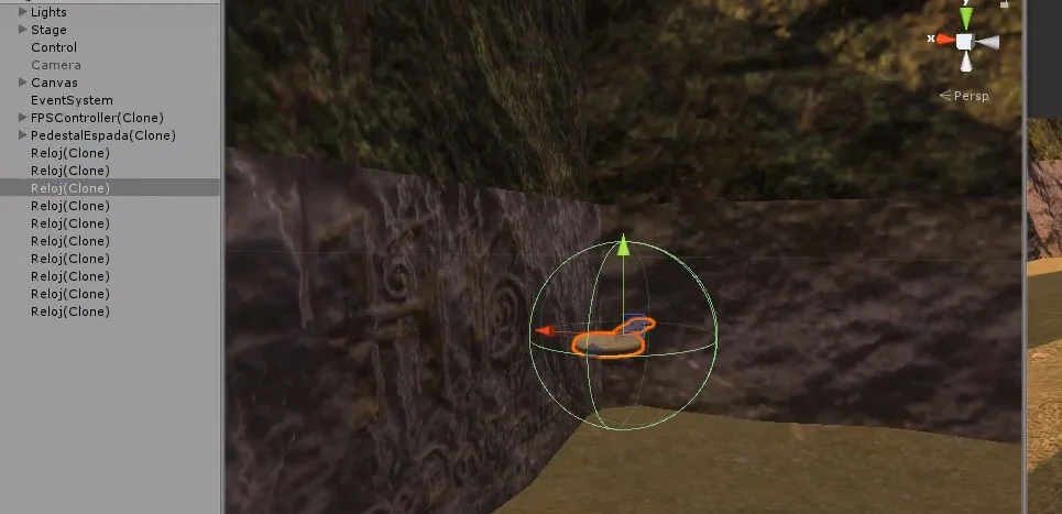


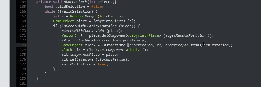

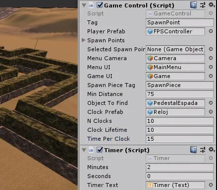

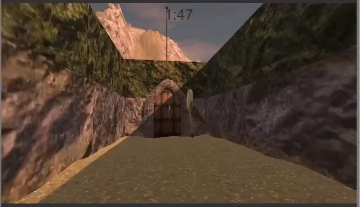

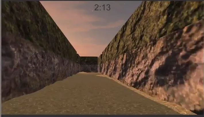
![[UNITY 3D] Randomness #2. Method to INSTANTIATE the object to find.](https://i.ytimg.com/vi/8J5NM7TxFPE/hqdefault.jpg)


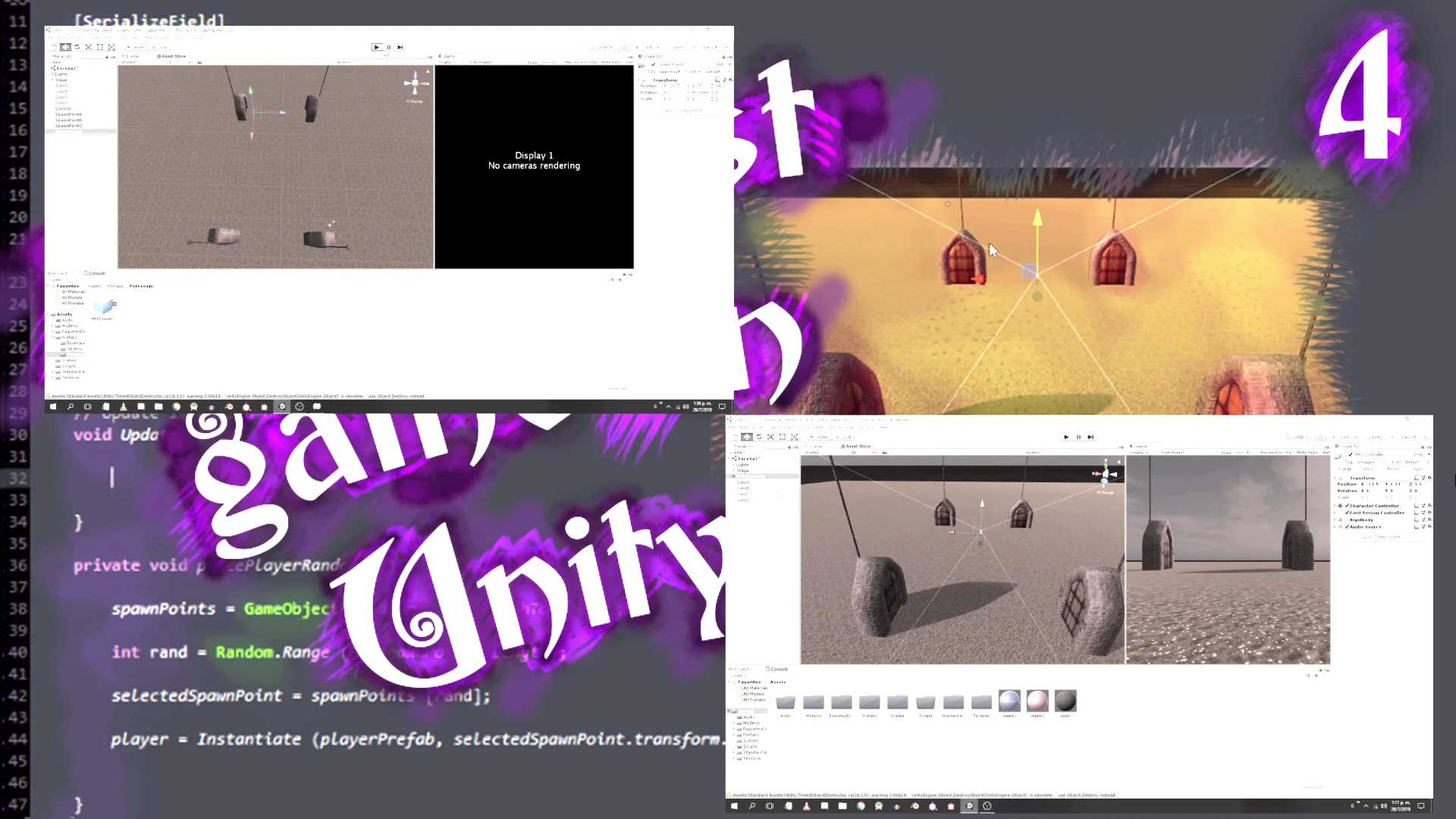


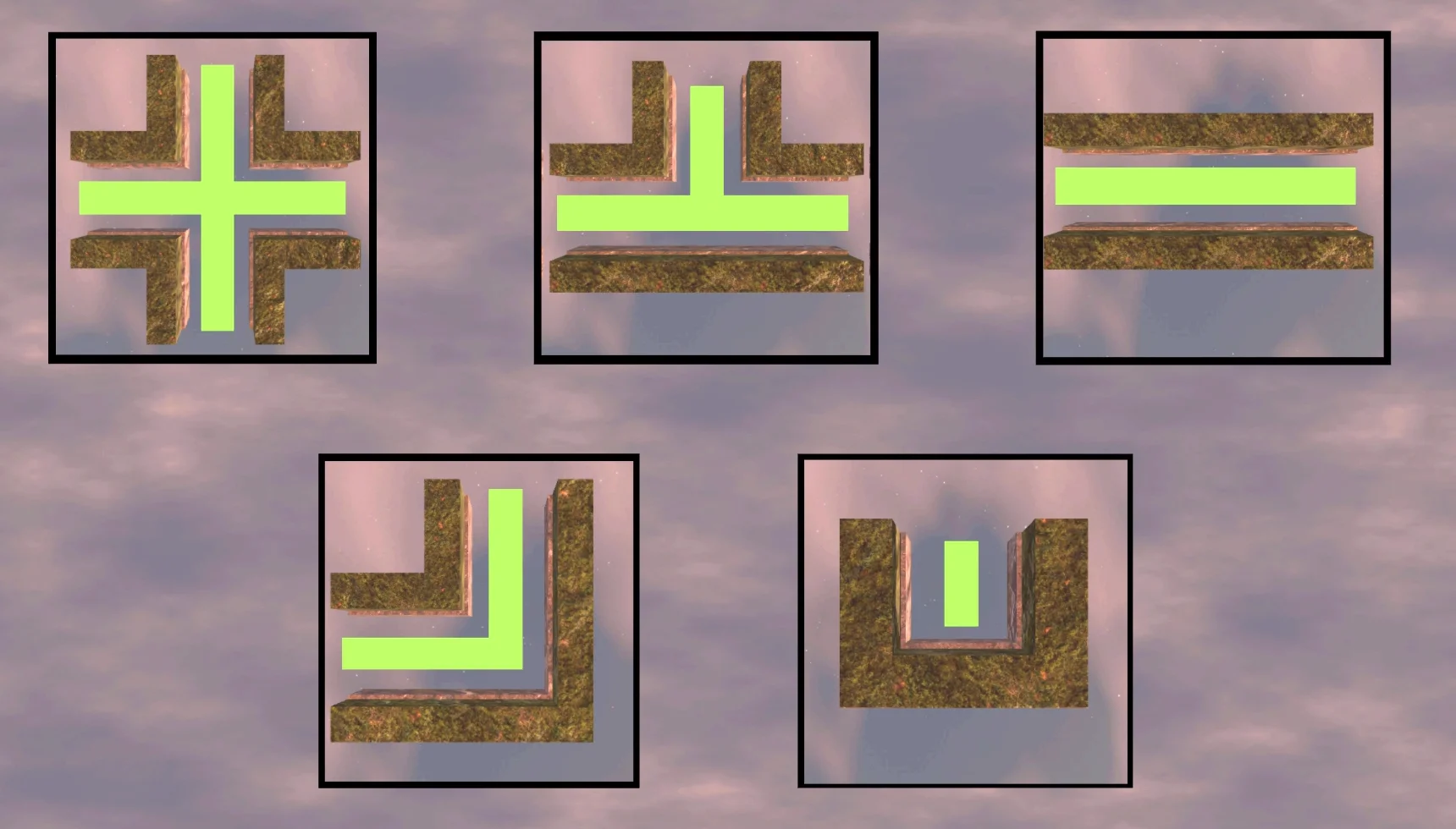


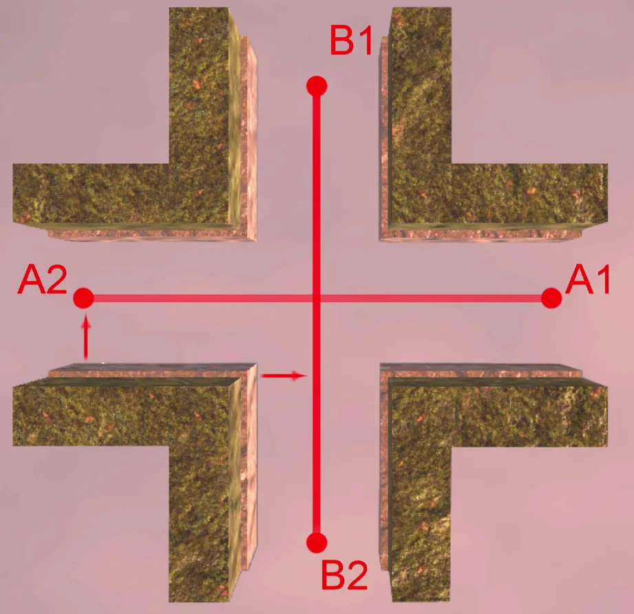

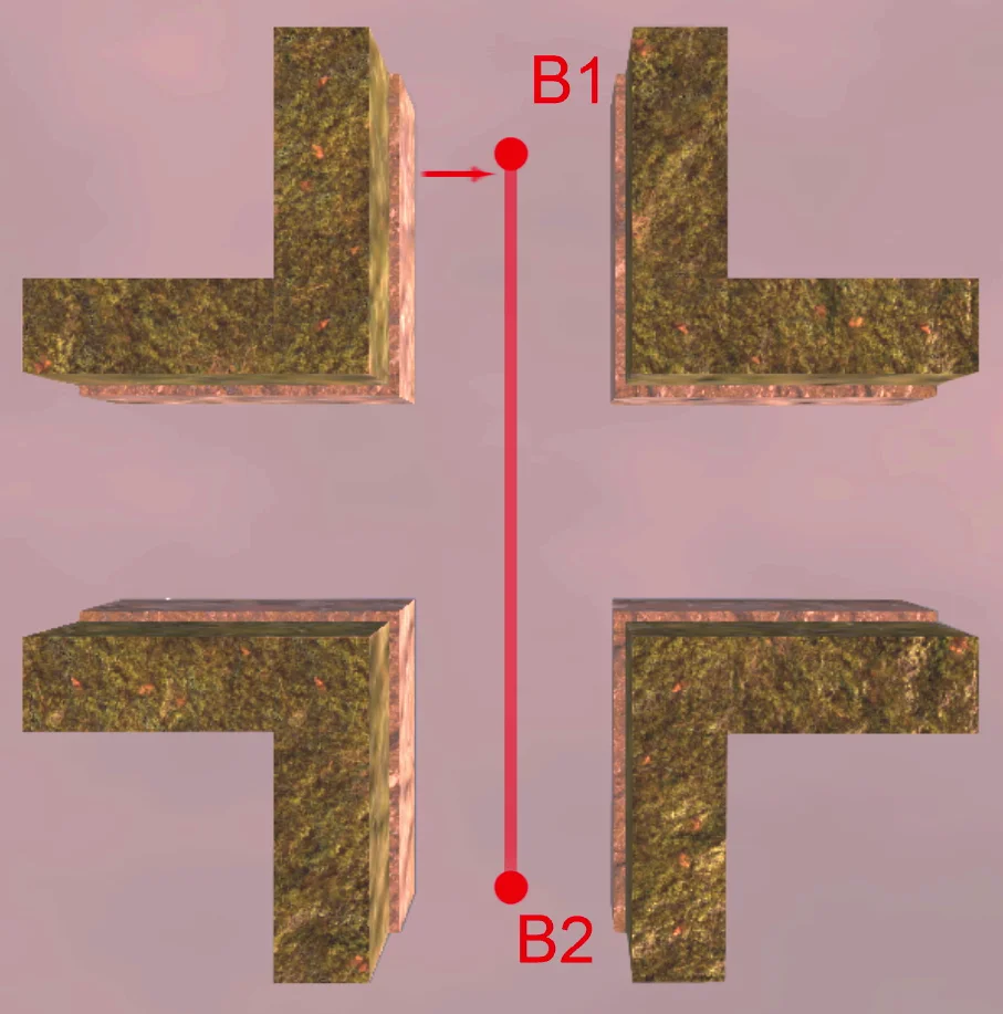

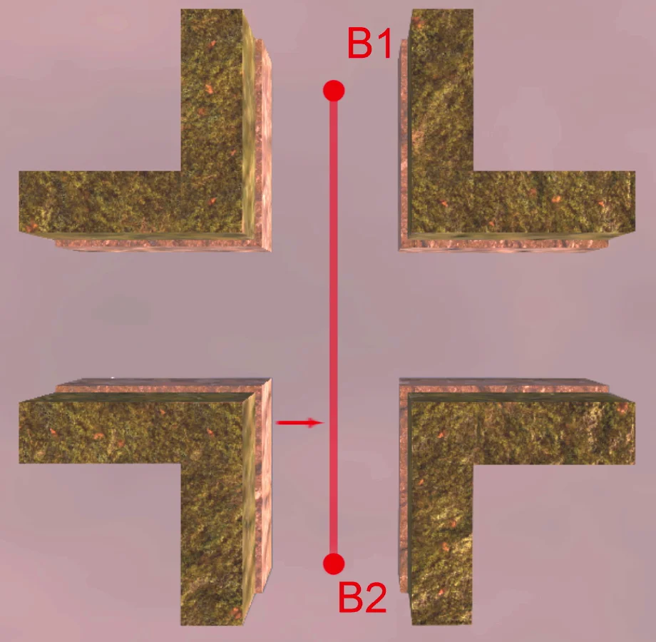

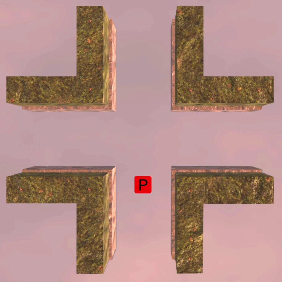


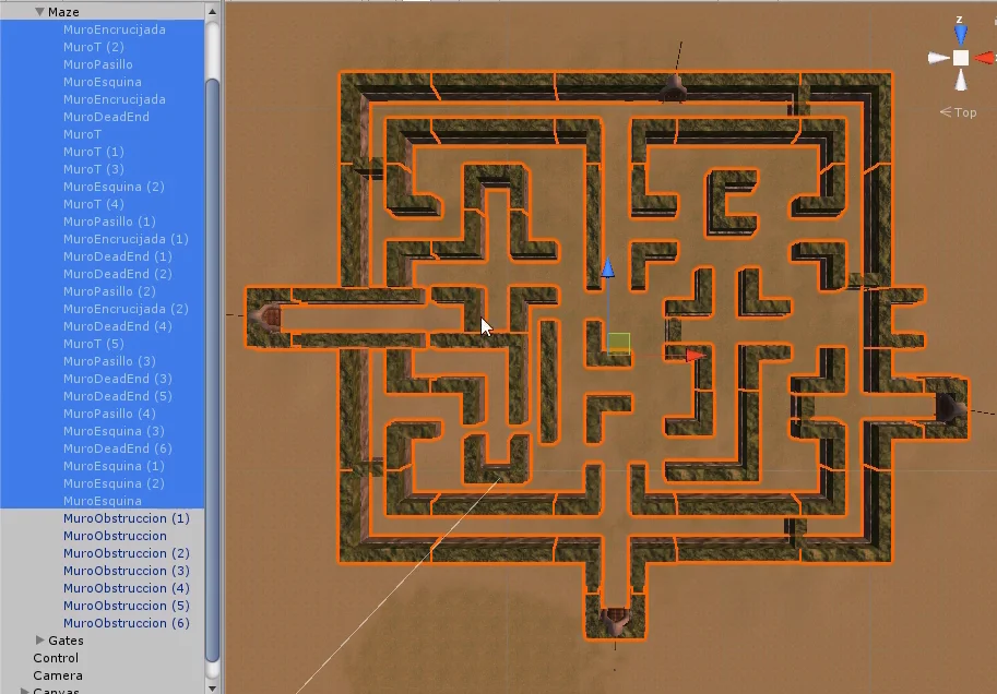


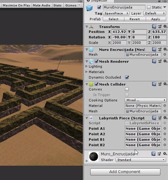

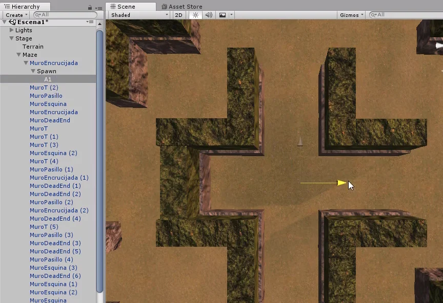


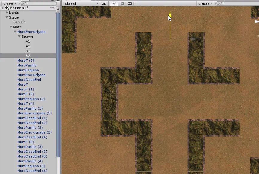

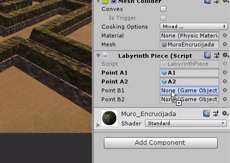

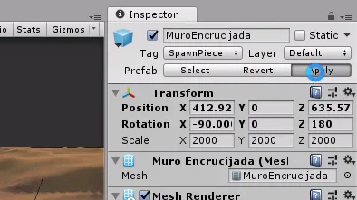

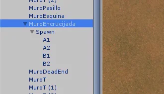

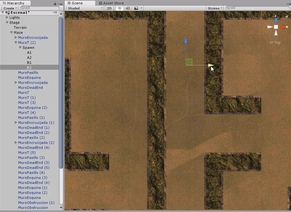

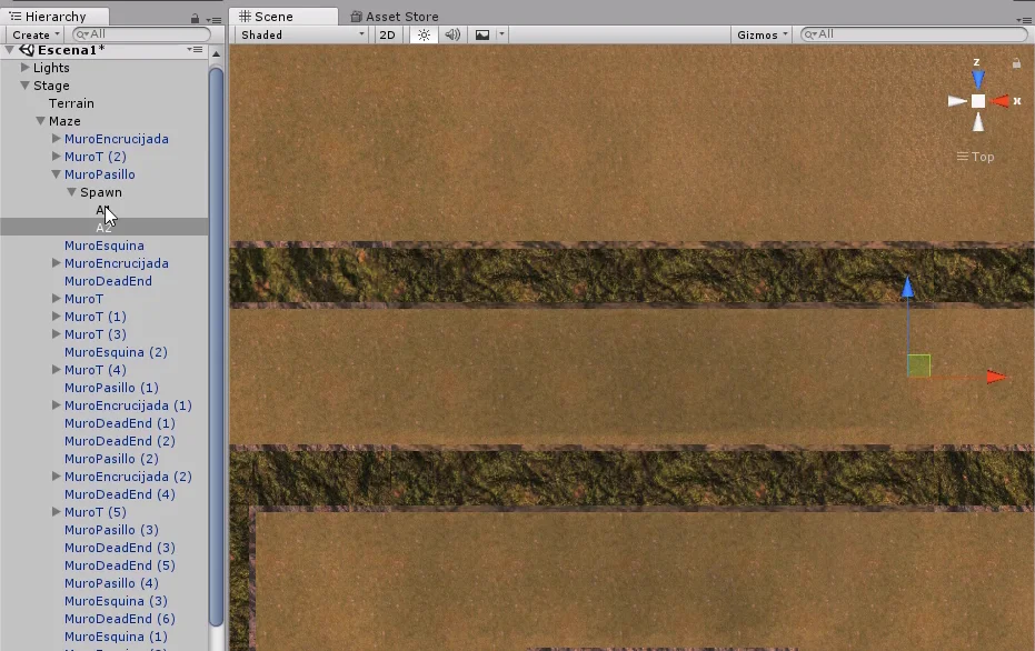


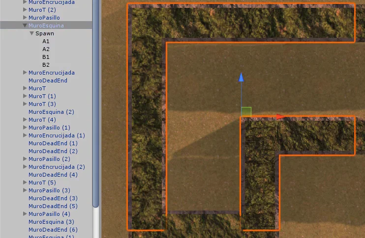

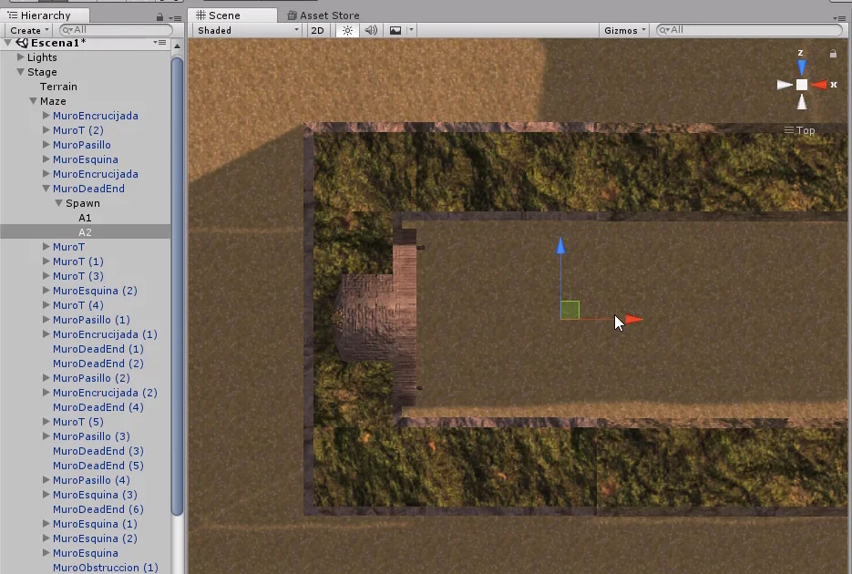

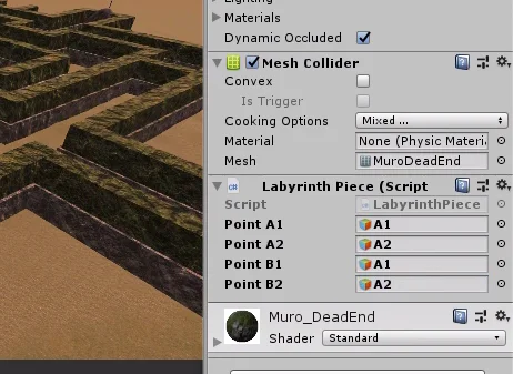


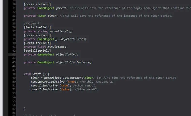


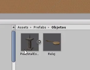


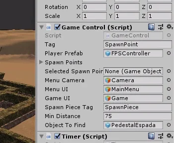

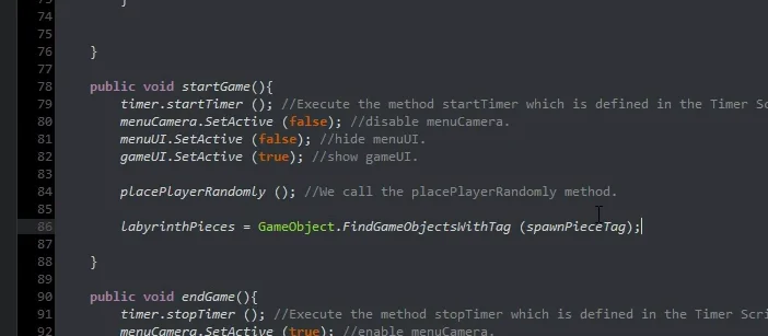

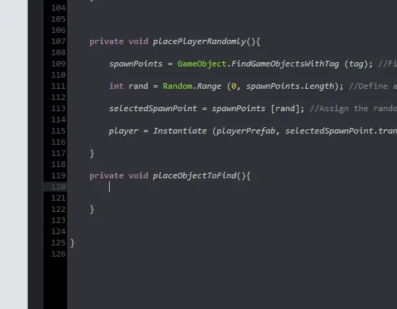


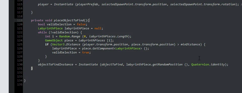

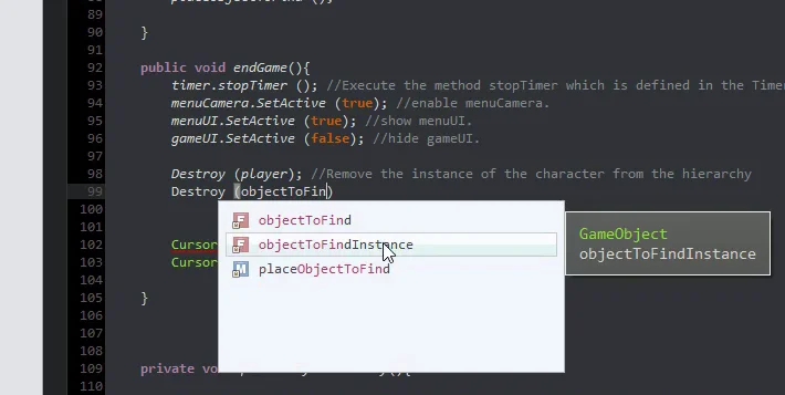

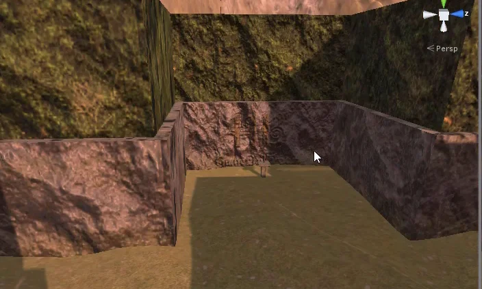

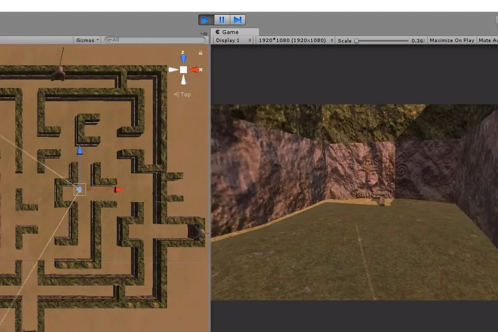

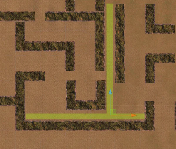

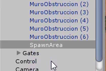

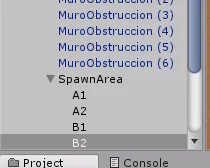

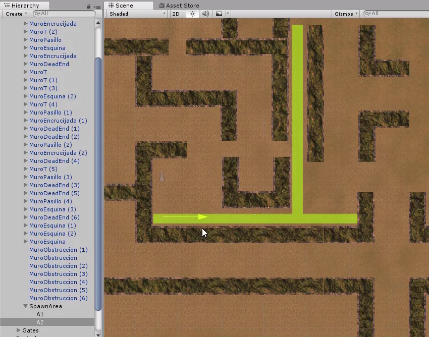

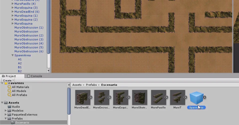

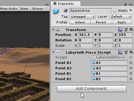


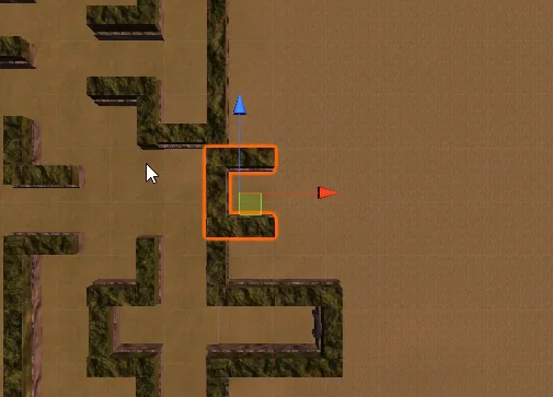

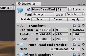
![[UNITY 3D] Game Design. Modeling mountains in Unity.](https://i.ytimg.com/vi/Cm9eGK0dRts/hqdefault.jpg)