This is the last exercise in Unity’s Fundamental Series, in this article we’re going to see how to change the scene in Unity at runtime.
Understanding how to change the scene is important because it allows us to separate the content of our game into parts, for example the main menu on one side and the game itself on the other. Another example could be a village with different buildings in which you can enter, the village can be built in a scene and then use multiple scenes for each building, or use a scene for all buildings and choose the appropriate one at the time of loading the scene.
Before we start I invite you to watch the video I made to summarize this article. English Subtitles available.
Maybe you find it useful…
I invite you to see this article and its respective video on how to achieve a Fade In / Fade Out effect in Unity, you can apply this to what we see in this article to achieve a change of scene not abrupt.
Each scene in Unity contains its own hierarchy of GameObjects, depending on our needs we can use them in different ways.
Some simple examples of using scenes are using one scene for the menu and another for the game, each scene is a level of our game, do everything in a single scene, etc..
In our projects we probably have to make changes of scene, that’s why I consider it part of one of the fundamental things of Unity.
GameDevLab LoadScene Station
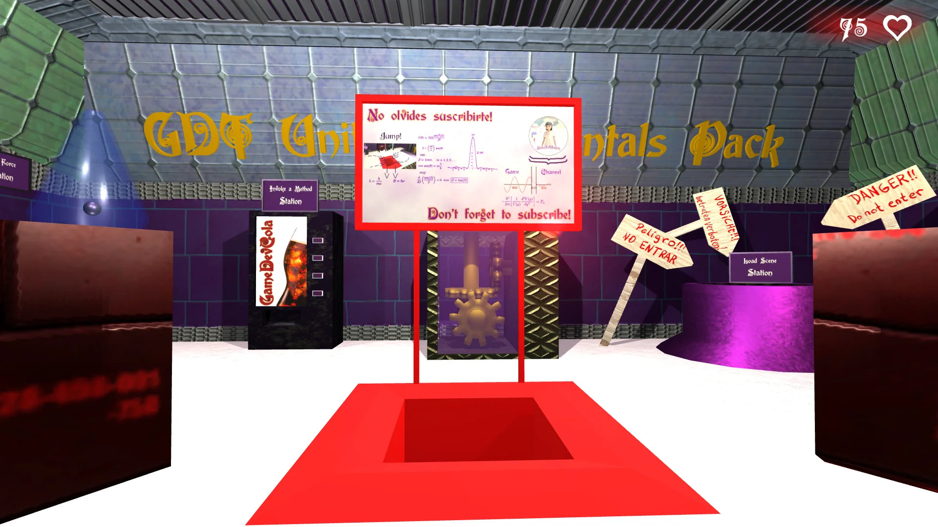
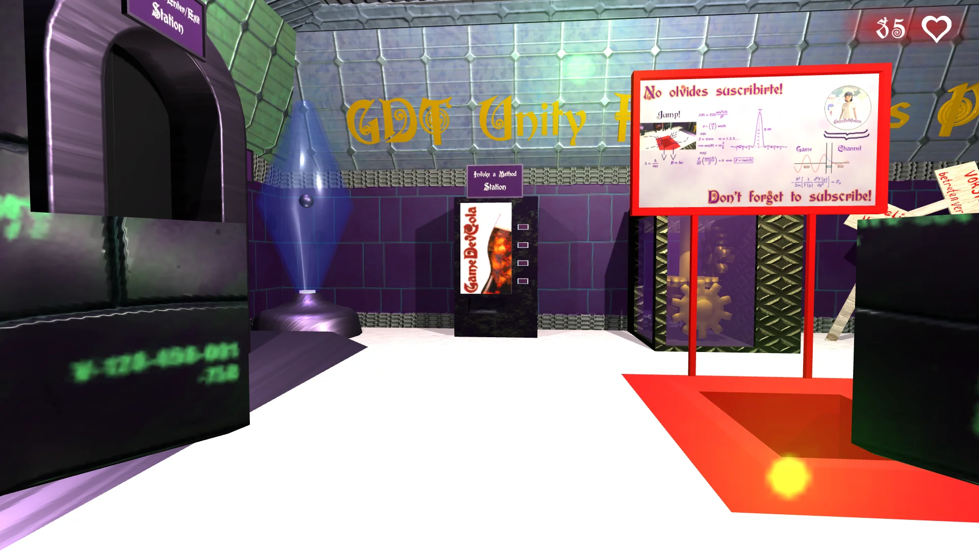
To learn how to change a scene in Unity we’re going to use GameDevLab’s LoadScene station, which consists of a strange well that looks like it disintegrates matter and sends it through space-time.
Fig. 1: Front view of LoadScene station.
Fig. 2: Inside the well of the LoadScene station.
Fig. 3: Inside the well of the LoadScene station.
At the bottom of the well there is a capsule (figure 4) that has a Collider assigned in trigger mode and a Script that will detect the character and send a message to the Script that we have to complete.
Fig. 4: At the bottom there is a capsule with Collider in trigger mode.
The complete station is contained in the GameObject “#10 LoadScene” of the hierarchy, this GameObject is assigned the Script “LoadScene” which is the Script we have to complete in this exercise.
Fig. 5: Project hierarchy.
Fig. 6: LoadScene station components.
The Script to complete contains a single public method called “teleport”, this method will be executed by the capsule Script when the character is detected at the bottom of the well.
What we are going to do is change the scene within the method “teleport”, for this we go to the folder scenes of the pack of the fundamental series and we see that there are two scenes (figure 8), one is the GameDevLab and the second scene is GameDevDimension, the latter is the one we are going to load using its name.
Fig. 8: Scenes from the project, GameDevLab and GameDevDimension.
Solution
To start with we have to import the namespace UnityEngine.SceneManagement
Fig. 9: Imported libraries at the top of the script.
Then to change the scene in Unity we execute a static method of the “SceneManager” class, the LoadScene method, to which we pass as parameter a String with the name of the scene we want to load.
Fig. 10: Method to change the scene in Unity.
With that simple instruction we can make the scene change, but for this to work all the scenes have to be added to the compilation, this we do in File > Build Settings, opening each scene and clicking Add Open Scenes.
Fig. 11: Scenes are added in Build Settings.
When the character falls into the pit a new scene is loaded in which the camera automatically advances and the controls are disabled, when the camera reaches the end of the tunnel the GameDevLab scene is automatically loaded again.
Fig. 12: Entering game mode and falling into the pit loads the GameDevDimension scene.
Fig. 13: Tunnel view of the GameDevDimension scene.
Fig. 14: Tunnel view of the GameDevDimension scene.
Fig. 15: Tunnel view of the GameDevDimension scene.
Conclusion
To change a scene in Unity we need to import the UnityEngine SceneManagement library and use a static method of the SceneManager class.
We can refer to a scene by its name or by its identification code that appears in Build Settings, in this case we use the name.
Loading a new scene is a relatively simple task, the problem is that the new scene is predefined and always starts from scratch.
For example a scene can be a house with ten coins, the character enters, takes the coins and leaves the house, ie returns to the previous scene. If we do nothing about it, when we re-enter the house scene the ten coins will be inside again.
To prevent this we have to store information of the state of the variables in the scene and read this information at the beginning of the scene.
Introduction
In this article we’re going to see how to rotate objects in Unity. There are several ways to achieve this, in this case we will use the Rotate method of the Transform class, this will directly modify the rotation parameters that are observed at the top of the inspector with the GameObject selected.
In order to describe mathematically we have to know directly or indirectly the following parameters:
-Rotation axis
-Amount of angles to rotate
-Sense of rotation
Let’s imagine that the object we want to rotate is a sphere. We take it in our hands and stick a rod through the exact center of the sphere. Then we take the rod and orient it from north to south parallel to the ground. Finally we make it turn counterclockwise.
Were you able to visualize it in your mind?
My description of the rotation was accurate although perhaps it was not drafted in the best way to be understood. However, let us assume that we could all have imagined exactly the same thing.
In the first place we can say that the axis of rotation is the rod. If we become strict the axis of rotation is an imaginary line that passes through the two ends of the rod.
The number of angles to rotate is half a turn, this mathematically is 180° or π radians.
The direction of rotation is counterclockwise or counterclockwise.
These three parameters can be fully described using a vector, which is what we are going to do in this article.
Workstation
We are going to use the rotation station which consists of three gears that are oriented in the direction of the world’s three x,y,z axes.
Fig. 1: Front view of the gear mechanism to be used.
The three gears are positioned perpendicular to each other.
Fig. 2: Side view of the gear mechanism to be used.
In the hierarchy we can find them inside the GameObject “#9 RotateObjects”. They have the names GearX, GearY and GearZ indicating the axis of rotation of each gear.
Fig. 3: In the hierarchy we have a GameObject for each gear.
The script to complete is called “RotateObjects” and is assigned to GameObject with the same name in the hierarchy.
In figure 4 we see that the three GameObjects of the hierarchy are already assigned in the fields of the inspector.
Fig. 4: The gears are assigned in the fields of the Script Rotate Objects.
When opening the Script we find the FixedUpdate method defined and inside some comments that say that the gears must be rotated there.
The FixedUpdate method as its name indicates is an update of the object state but executed at a certain fixed time.
This means that no matter how much the frame rate of the game changes, we will have the same number of executions of this method per second.
Colocaremos en el método FixedUpdate una instrucción que hará que los engranajes giren una determinada cantidad de ángulos en algún sentido respecto de un eje. Esto significa que en cada llamada de FixedUpdate se aplicará la rotación, lo que generará un movimiento continuo de rotación.
Fig. 5: Fields defined in the RotateObjects Script.
Fig. 6: Script when first opened. The FixedUpdate method is defined.
Solution
The Rotate method of the Transform class has different versions, we are going to use one in which the first parameter is the vector that completely expresses the rotation and in the second parameter we indicate the type of coordinates to use, global coordinates that are unique in the whole world of the game or local coordinates that are specific to each particular object, which would be as if each object had its own north.
Fig. 7: Instructions for rotating each gear in relation to its own axis.
By mathematical properties of the vectors I rewrote the vector as the product of its module or norm multiplied by a unit vector (norm 1) describing the direction.
This allows us to separate on the one hand the direction of rotation and on the other hand the number of angles to rotate.
Fig. 8: Modifying the variable in the inspector we can change the speed of the set of gears.
Another advantage of expressing the vector that way is that we can change the direction of rotation simply by using negative values in the inspector.
Fig. 9: Using negative values the rotation of the gear set can be reversed.
Conclusion
You can simply rotate objects in Unity using the Rotate method of the Transform class.
If we don’t need mathematical precision, we can play with numbers and get different results.
With this type of rotation we directly affect the rotation vector of the Transform component, this is fine if we seek to show only the animation rotation. If the rotation is needed to produce physical interactions, RigidBody should be used.
IMPORTANT UPDATE
This article belongs to an old series of the channel, currently there is a video available that explains better how to use the Invoke function to make a function be called with delay, you can watch it here:
In this article we are going to see how to use the Invoke method of Unity’s MonoBehaviour class to execute an action with a certain delay. This allows us for example to create mechanisms that work for a while.
Before we start I invite you to watch the video I made to summarize this article. English Subtitles available.
Procedure
To analyse the Invoke method we’ll be using the GameDevLab’s “Invoke a Method” station, which is a vending machine for the refreshing new GameDevCola that not only quenches thirst but also heals your wounds.
Fig. 1: GameDevLab “Invoke a Method” station. GameDevCola vending machine.
By approaching the machine we can interact with it using the E key. When you press it, the machine will become inactive, that is, you will not be able to interact with it for a while. After a few seconds the machine will eject a can of GameDevCola and seconds later will again be enabled for interaction.
Fig. 2: Script InvokeAMétodo sin completar.
In the script to complete we have the methods “DeliverACola” and “PrepareMachine” that will deliver the drink and enable the machine respectively.
Then we have redefined the OnTriggerStay method that allows us to check if the character is standing in front of the machine.
Within this method we check if the Tag of the GameObject is that of the player, then if the machine is ready (boolean machineReady), we tell the UIManager object that can interact and this is responsible for displaying the message on screen.
Then we check if the E key is pressed. At this point the machine receives a request for a GameDevCola. The first thing you do is deactivate the machine and then in the region with comments is where we must complete the missing code.
Analysis of events in time
I want to emphasize this part because it is important to understand the idea.
When we call a method in C#, the execution of it is done at that precise instant, all instructions are solved even before refreshing the screen image.
So if we called the methods directly in the region marked with comments, what would happen is that the can would be expelled and the machine enabled again in the same instant in which the E key is pressed. As illustrated in the timeline in figure 3.
Fig. 3: Diagram of events in time. This would happen if we called the methods directly.
Figure 3 shows a timeline in which there are two different points in time, the first point being the beginning of the game. Sometime later in time is the second point, in which the player asks for a can, the machine delivers it and it is enabled again, these three actions at the same time.
Fig. 4: Diagram of events in time. This is what we want to achieve.
Figure 4 shows four different time points.
Point 1: Start of the game.
Point 2: The player orders the GameDevCola.
Point 3: X milliseconds after the order is placed, the machine delivers the can.
Point 4: After Y milliseconds of can delivery, the machine is enabled again.
This is what we are going to do using the Invoke method of the MonoBehaviour class.
Solution
The Invoke method can be called directly without reference to a class.
We must indicate two parameters, the first is a String with the name of the method we want to invoke, the second parameter is a float to indicate the number of seconds that will pass until the method is finally executed.
Upper and lower case must be respected. If we get confused at this point, a bug may arise that is difficult to track. If the method is called “DeliverACola” and we invoke the “DeliveraCola” method what will happen is that we will try to call that method but as it is not defined, the program will go ahead without executing those instructions.
Fig. 5: InvokeAMethod script completed.
Figure 5 shows the resolution for the exercise. The can will be delivered two seconds after the player presses the E key and the machine is re-enabled four seconds later.
Fig. 6: When approaching the machine, a sign appears indicating that it is possible to interact.Fig. 7: After a few seconds of interacting with the machine, we are given a can.
Conclusion
The Invoke method is used to postpone the execution of a method. Although it is not the only way to achieve this, it is a simple resource, easy to remember and easy to implement.
Introduction
In this article we are going to study how to use the AddForce method of Unity’s RigidBody class, which allows us to apply forces to GameObjects that have a RigidBody component assigned to them. The goal is to make the ball in the GameDevLab bounce indefinitely for the duration of the game.
We are going to use the “AddForce” station, which consists of a diamond-shaped container with a ball inside. The objective is to make the ball bounce indefinitely inside the station. To do this we must apply a force when the ball hits the bottom.
Fig. 1: GameDevLab AddForce Station.
In the hierarchy we have the GameObject “#7 AddForce” that contains all the elements of the station (figure 2). This GameObject is also assigned the Script “AddForceToObject”.
Fig. 2: Hierarchy of the GameDevLab. Let’s work with the GameObject “#7 AddForce”.Fig. 3: Componente “AddForceToObject” asignada al GameObject “#7 AddForce”.
In figure 3 we see the “AddForceToObject” component in the inspector. We can assign an object to which to apply the force, in this case is “Sphere” the ball that is inside the station. We can assign a minimum and maximum force value to apply to the ball and the direction of the force.
Fig. 4: To the left, the sphere of the “AddForce” station. On the right, its components are displayed in the inspector. Between them there is a RigidBody component that will give you physical behavior.
The Ball GameObject is simply a primitive sphere made in Unity, it is assigned a RigidBody component that gives it physical behavior. The ball will be affected by gravity, it will be able to collide with objects that Colliders have assigned and we will be able to apply forces to it.
Fig. 5: To the left the GameObject in charge of detecting if the ball touches the ground. To the right its components in the inspector.
At the base of the structure we have a cylinder-shaped GameObject that has a Box Collider assigned in Trigger mode (figure 4). It also has a script called “AddForceCollisionDetection” that will detect the ball.
Solution
When we open the “AddForceToObject” Script for the first time we find what you see in figure 6. All the parameters you see in the inspector are defined and it contains only one method called “addForce”. This method is defined as public because it is the one that is going to be called when it is detected that the ball has touched the ground of the structure.
Fig. 6: Script “AddForceToObject” incompleto.
The solution of this exercise is shown below and the purpose of each instruction is explained.
Fig. 7: Solution of the exercise.
To solve this problem we will require three instructions. The first will define the magnitude of the force to be applied, which will be a random value between the minimum and maximum forces.
The second instruction will define the total force to apply, if you saw the video about physics, to define a force we need a magnitude and a direction. For the direction we use the vector of three dimensions (class Vector3) that is seen in the inspector, it is called “forceDirectionVector”. But we are not going to use it as it is written in the inspector. To prevent that Vector3 from affecting the magnitude of the force we must normalize it. We do this with the “Normalize” method of the Vector3 class. The total force to apply will be a Vector3 called “force” which is the result of multiplying the direction by the magnitude.
Finally the third instruction consists in applying force on the object. The forces are applicable to GameObjects that have a RigidBody component assigned, in our case we are going to apply the force on the RigidBody component of the ball. We use the “GetComponent” method to obtain the RigidBody component and finally we execute the AddForce method, passing as parameter the force to apply.
Fig. 8: Station running. The ball bounces with variable force.
Conclusion
When testing the game, the ball rebounds indefinitely with a random force.
To define a force we need a real value for the magnitude and a vector for the direction in which it should be applied.
The forces act on the RigidBody component of a GameObjects.
IMPORTANT UPDATE
This article is part of an older video series, I recently upload a Unity prototype to help understanding how the OnTrigger system works, how to configure the objects from the scene and how the functions are called.
The following video has summarized information about the OnTrigger events, how to setup the components and how to define the events in a script.
In this article we are going to study how to use the OnTriggerEnter (Collider c) and OnTriggerExit (Collider c) methods to detect the player in a given region and apply actions when that happens. Specifically we are going to make the GameDevLab door open when the player is in front of it and close when it moves away.
We are going to use the “OnTriggerEnter/Exit” station, which consists of a portal that leads to a small room that for now has nothing special.
Initially the door is closed, our goal is to detect the character when he approaches and open the door to let him in and away from the portal the door must close.
Fig. 1: GameDevLab OnTriggerEnter/Exit Station.
All elements of the station are contained in the GameObject “#6 OnTriggerEnter/Exit”.
Fig. 2: Hierarchy of the GameDevLab. Let’s work with the GameObject “#6 OnTriggerEnter/Exit”.
This GameObject is assigned the script “OnTriggerEnterExit” which is the one we have to complete on this occasion.
Fig. 3: Components of the GameObject “#6 OnTriggerEnter/Exit”. We have assigned the Script to complete in this exercise and a Box Collider in trigger mode.
In addition to a Mesh Collider so that the character does not cross the structure, it also has a Box Collider in Trigger mode, as seen in figures 3 and 4.
Fig. 4: Box Collider in trigger mode that we will use to detect the character.
Let’s use this Collider to solve the exercise.
Fig. 5: Opening the door once we solve the exercise.Fig. 6: View from inside the room.
When we open the OnTriggerEnterExit Script for the first time we find two methods, the openDoor() method that will open the door and the closeDoor() method that will close it.
In addition, the region where the redefinition of the OnTriggerEnter(Collider c) and OnTriggerExit(Collider c) methods is suggested is indicated with green comments.
Fig. 7: Script OnTriggerEnterExit sin completar.
We’re not going to worry about how the door opens and closes because that’s already solved in GameDevLab.
How the OnTriggerEnter(Collider c) and OnTriggerExit(Collider c) methods work
In the previous article we saw how the OnTriggerStay method worked and we used it to make the damage and regeneration stations affect the player’s health.
For the OnTriggerEnter and OnTriggerExit methods the same requirements are needed, what changes is the moment they are executed.
Fig. 8: Components required for the operation of the methods.Fig. 9: The OnTriggerEnter method is automatically executed on the first frame in which a collider enters the trigger.
OnTriggerEnter runs the moment the player enters the trigger for the first time, i.e. the previous frame of the game was outside the trigger and the current frame is inside.
Fig. 10: The OnTriggerExit method is automatically executed on the first frame in which a collider exits the trigger it had previously entered.
On the other hand, the OnTriggerExit method is executed at the moment in which the player leaves the trigger, that is to say in the previous frame of the game it was inside the trigger and in the current frame it is outside.
Fig. 11: Overview of the operation of the methods.
With this in mind, what we can do is open the door in the OnTriggerEnter method and close it in the OnTriggerExit method.
In addition we are going to verify that the tag of the Collider that entered in the trigger is equal to “Player”, of that form we know that it is about the player. The following figure shows the resolution.
Fig. 12: Resolution of the exercise within the region defined by the green comments.
Conclusion
The OnTriggerEnter and OnTriggerEnter methods allow us to detect GameObjects that enter a certain region, this has a number of applications, for example activate kinematics, mechanisms, allow us to perform certain actions only when we are in a certain region, and so on.
Unlike the OnTriggerStay method, these methods are run only once when one of the above situations occurs.
Introduction
In this article we are going to see the absolute value function of a number, what are its properties, some graphics and as an extra we are going to see how to calculate the absolute value of an expression in the Unity graphic engine, in the field of programming and game development.
Definition of the Absolute Value of a Number
The absolute value of a number is the distance between that number and the 0 of the measurement system.
This results in two possible outcomes depending on the number in question.
If the number is positive, the result of taking the absolute value is the same number. If on the other hand the number is negative, when taking the absolute value the result is the same number but in positive value.
Formally:
Because of this definition we can affirm that the absolute value of a number is always a positive number.
Graph of the Absolute Value of X
Below are some graphs of the absolute value function to understand how it behaves.
Observe in each graph the ranges of the variables in the axes to see how the graph is affected by the displacements in X in Y and by the coefficients that multiply the expression.
(1)
(2)
(3)
(4)
Distances
When we are working with different points in a coordinate system, we are often interested in working with the distances between them, which are positive values.
The absolute value allows working with these distances in mathematical expressions.
How to calculate the Absolute Value in Unity
To calculate the absolute value of an expression in Unity, we must make use of the static method “Abs” of the class “Mathf”.
Let “num” be a numerical variable defined in the program in question, to take its absolute value we do:
Mathf.Abs(num);
The result of the execution of this method can be stored in another variable or in the same one, in the following way:
num = Mathf.Abs(num);
Introduction
In this article we are going to talk about the summation and product notation, what they mean and how to perform the calculations. At the end we will see how to program summation and product notation in Java or C# language.
What is summation and product notation?
Summation and product are ways of defining mathematical operations that consist of sequences of sums and products respectively.
Imagine that we have to add or multiply all the numbers starting at 1 and ending at 1000, but also multiply each of them by 3.
Using symbology we can write long operations like that in short. In addition the properties can help us to simplify the expression and to calculate the results.
Sigma Notation
In the next video you can see the concept of the sigma notation and an excercise solved using programming techniques in Unity.
The summation is symbolized by the Greek letter Sigma in capital letters.
Below the summation symbol the index variable is indicated and from which value it starts. At the top of the symbol is the last value to be taken by the index.
To the right of the symbol is the expression that determines all the terms of the summation, each term arises from replacing the index in the expression from the first to the last value.
In equation 1 we see on the left side the expression of the summation and on the right side the developed operation.
(1)
How to program a Summation?
To implement the summation in some programming language is relatively simple, we must define a variable to accumulate the sum that must be initialized in 0 (neutral element for the sum). We have to take into account which numerical set the summands belong to, this will depend on the type of variable to choose.
We define an integer variable for the end of the summation.
We make a for loop that goes from the beginning of the summation to the end and inside the loop we define the operation to make.
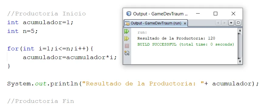
In figure 1 we see the implementation of the sum of equation 1 together with the printed result in console.
Fig. 1: Implementation of the summation of equation 1 in Java, Netbeans IDE.
Symbol of Product notación
The product notation is symbolised by the letter Pi in capital letters.
Under the producer symbol is indicated the index variable and from which value it starts. In the upper part of the symbol is indicated the last value that the index will take.
To the right of the symbol is the expression that determines all the terms of the producer, each term arises from replacing the index in the expression from the first to the last value.
In equation 2 we see on the left side the expression of the producer and on the right side the developed operation.
(2)
Implement the product notation in programming
We must define a variable to accumulate the product that must be initialized in 1 (neutral element of the product). We also analyze the type of numbers we are multiplying to choose the type of the accumulation variable.
We define a whole variable for the end of the producer.
We make a for loop that goes from the beginning of the production to the end and inside the loop we define the operation to be performed.
In figure 2 we see the implementation of the producer of equation 2 together with the printed result in console.
Fig. 2: Implementation of the equation 2 producer in Java, Netbeans IDE.
Introduction
The Cartesian coordinate system is named after the philosopher and mathematician René Descartes, considered the creator of analytical geometry.
This system allows us to represent points on a line, in the plane and in space using arrays of numbers. For example: (1,5), (-3,0), (4,1,-1), etc.
What is a Cartesian plane?
The Cartesian plane is defined by two straight lines perpendicular to each other, one horizontal and one vertical, these straight lines are known as Cartesian axes. Using these axes we can identify any point on the plane with a single ordered pair of numbers.
The horizontal axis is known as the abscissa axis and is usually the x-axis. The vertical axis is known as the ordinate axis and is usually the y-axis.
The point where the abscissa and ordinate axes are cut is known as coordinate origin or simply origin and is the point (0.0).
The following figure shows a Cartesian plane with the point (2,1) plotted.
Fig. 1: Plano cartesiano xy con el punto (2,1) representado.
Quadrants of the Cartesian plane
Quadrants are characteristic regions of the plane defined by changes in signs on coordinate axes.
There are four quadrants, the first is the upper right region and they are listed counterclockwise.
Fig. 2: Identification of the quadrants of the Cartesian plane.
As shown in figure 2, quadrants are defined in the following regions.
First quadrant: { x > 0 , y > 0 }
Second quadrant: { x < 0 , y > 0 }
Thirdquadrant: { x < 0 , y < 0 }
Fourthquadrant: { x > 0 , y < 0 }
Representation of functions in the Cartesian plane
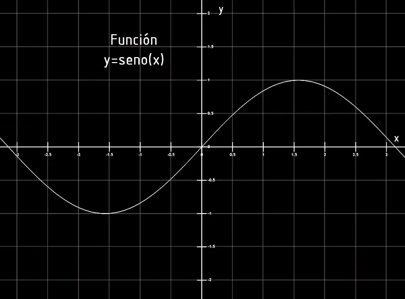
The Cartesian plane also serves to represent functions, i.e. rules that assign each point of the x-axis to a point of the y-axis. Figures 3 to 6 show some examples of function graphics in the Cartesian plane.
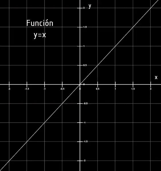
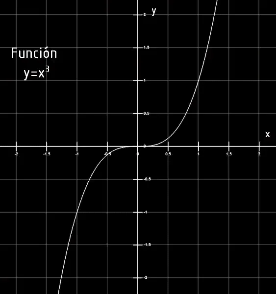
Fig. 3: Graph of a linear function.Fig. 5: Graph of a cubic function.
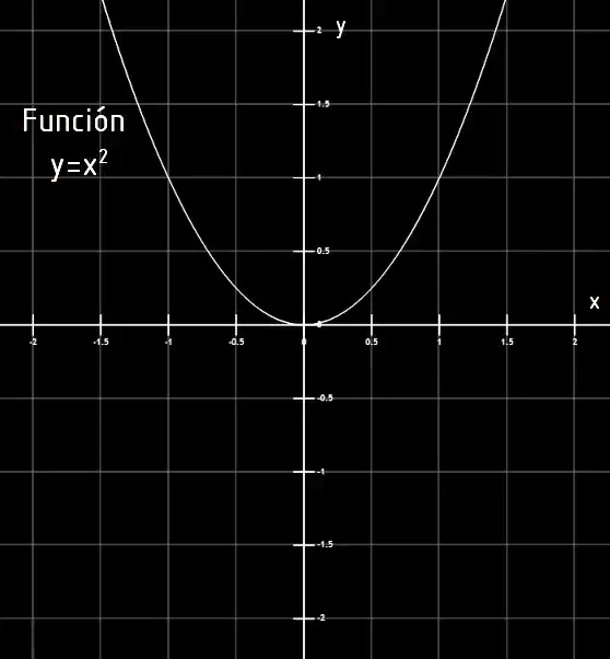
Fig. 4: Graph of a quadratic or parabola function.Fig. 6: Graph of a sine function of x.
Cartesian system in Unity
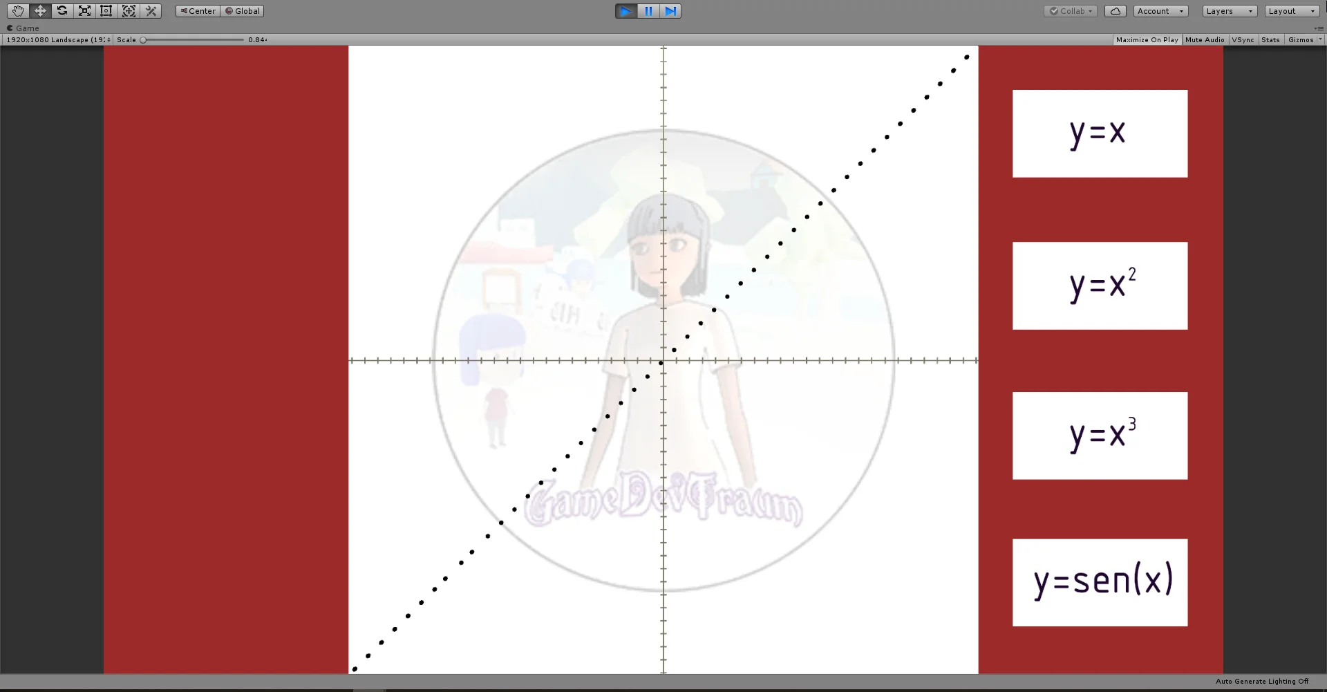
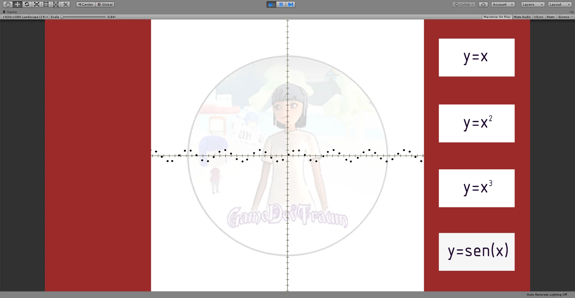
Cartesian coordinates are used in various places in Unity, for example to define the position of a GameObject in the plane or space. But for the purpose I wanted to make a simple function plotter using spheres that move on the x-axis and their position on the y-axis is calculated using the expression of the function.
The buttons allow us to change the expression of the function
Fig. 7: The spheres move according to a linear function.Fig. 9: The spheres move according to a quadratic function.
Fig. 8: The spheres move according to a sinusoidal function.Fig. 10: The spheres move according to a sinusoidal function in one section and a linear function in another.
Conclusion
Rectangular coordinates are often used in Unity.
Understanding how the Cartesian plane is used to represent points and functions in the plane, along with knowledge of analytical geometry can help us create new and interesting solutions.
Introduction
Numeric sets are used to group numbers that have similar characteristics. It is one of the basic concepts of mathematics so it is important to understand what they are and what characteristics each has.
What are number sets used for?
Numeric sets are used to separate numbers into different classes that have similar properties.
We must see this simply as a form of organization, in which given any number we say that this number belongs to such a set.
Numerical Sets
The basic numerical sets are as follows:
Natural – ℕ
Integer – ℤ
Rational – ℚ
Real – ℝ
Complex – ℂ
Each more general set encompasses the previous set, i.e. for example all natural numbers are integers, but not all integers are natural.
Set of Natural Numbers (ℕ)
This set is made up of the numbers {1,2,3,…} (the suspension points indicate that the enumeration continues indefinitely), these numbers are all positive and represent integer magnitudes, i.e. they have no decimal part.
Set of integer numbers (ℤ)
If to the natural numbers we add the number 0 and the negative numbers without decimal part we obtain the set of integers. {…,-3,-2,-1,0,1,2,3,…}.
With negative numbers we can represent subtraction operations, missing magnitudes, values below the reference zero and so on.
Some examples are outgoing flows of money, that is, money that we pay and subtract from what we have; temperatures below zero are expressed as negative values of degrees Celsius.
Sets of Rational Numbers (ℚ)
The set of rational numbers arises from making divisions of two whole numbers. For example 1 divided 2 is an operation that results in a number that is smaller than 1 but larger than 0.
These numbers are used to represent non integer magnitudes, for example variables of continuous nature such as speed, weight, electric current; to express fractional quantities such as half a kilo of flour are 0.5 kg of flour.
Set of Real Numbers (ℝ)
If to the set of rational numbers we add the set of irrational numbers we get the set of real numbers.
Irrational numbers arise from performing certain operations and it is not possible to express them as the quotient between two whole numbers.
An example of this type of numbers is the well-known Pi number which is composed of infinite decimal digits.
Set of Complex Numbers (ℂ)
If we add imaginary numbers to the set of real numbers, we get the set of complex numbers. Any number we choose will be, in general terms, a complex number.
The imaginary number i is the result of the square root of -1.
Complex numbers are composed of a real part and an imaginary part and are very useful for the study of electrical circuits involving capacitive or inductive elements. They are also used in Fourier transform calculations.
Numerical Sets in Videogames
Modeling of game elements
To model the behavior of different elements in our game we will probably need to use different types of numbers.
For example a character may have a standard of living represented by hearts. When it is damaged it loses a heart and when it takes a healing potion it recovers a heart. In this case the health level is a whole magnitude.
We can also think, for example, that each heart can be divided into four parts and each blow received takes away a quarter of our heart. In addition it could be that a strong enemy takes away three quarters of our heart with each blow. In this case we are thinking of hearts as rational magnitudes and we are going to need decimal numbers to represent them.
It all depends on how we want our model to be.
Numerical sets in programming
To represent the different types of numbers we need to build models, we have elements called variables, which are spaces in the memory where information is stored.
The programming language we use in Unity offers us different types of variables.
Integers
To represent integer magnitudes we have for example the byte, the short, int and long
Each has its own range of representation, for example the int allows us to represent integers that are between -2,147,483,648 and 2,147,483,647. The short instead allows us to represent numbers between -32,768 and 32,767, which is also a fairly large range.
By default we are going to use the int variable type to represent integer magnitudes.
Reals
The floating point system is used to represent decimal values in computation.
We have 32-bit float type variables, 64-bit double type variables and 128-bit decimal type variables. Each one has a certain range of representation and precision.
In computation, infinite digits cannot be stored, so irrational numbers will be represented as rational numbers and a truncation error will arise.
Complex
Complex numbers can be represented with two real numbers, one is the real part and the other is the imaginary part, the latter will be multiplied by the number i. As expressed in the following equation:
Z = X + i . Y
X and Y being real numbers and Z being a complex number.
We can represent complex numbers using two floats with significant names for the real and imaginary parts, we can use two-component vectors, or we can use the Complex class of C#.
Conclusion
Numeric sets are names we use to classify the different types of numbers that exist.
Knowing the different types of numbers and their properties will help us in building models for our games.
Para implementar los números en programación contamos con elementos llamados variables. Existen distintos tipos de variables para representar números enteros y racionales, cada tipo tiene su propio rango de representación.
Introduction
In this article we are going to study how to use the OnTriggerStay method to detect the character in a certain region and apply actions when that happens. Specifically, we’re going to make the damage and health regeneration stations affect the character.
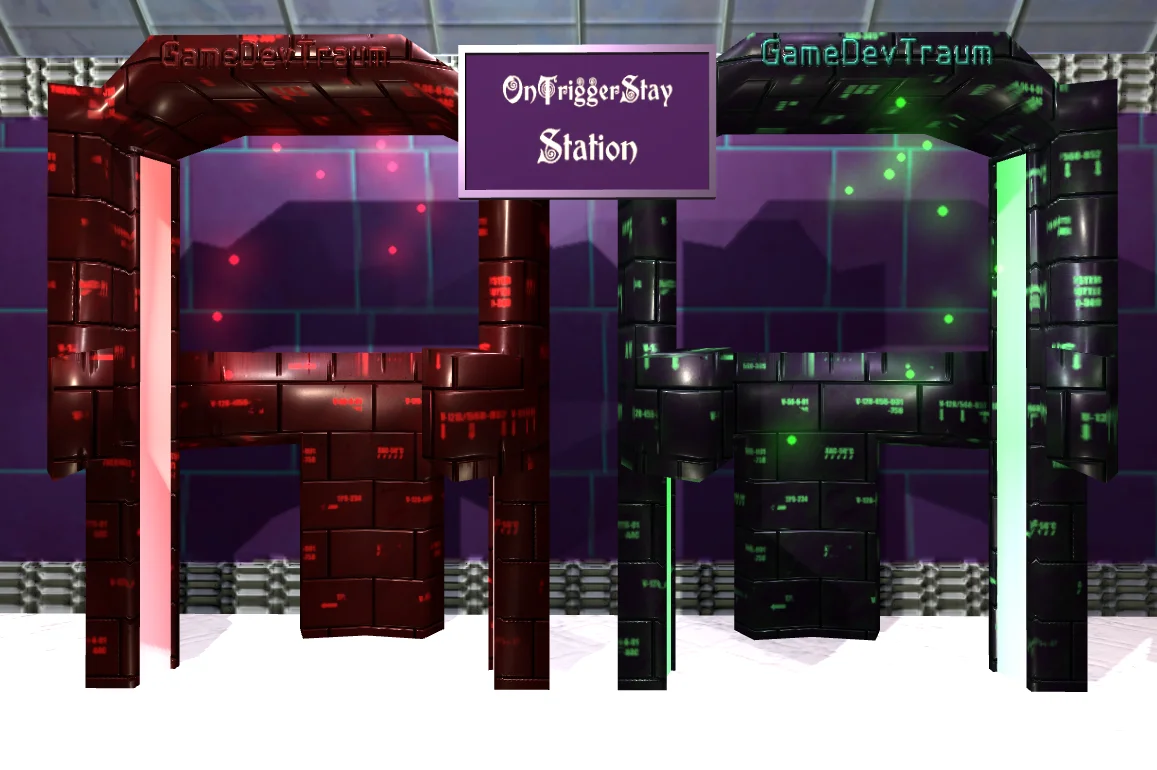
We are going to use the “OnTriggerStay” station, which consists of two metal-detector-shaped devices, one red and one green, whose function is to affect our health system. When entering the red station our health should decrease and with the green station it should increase.
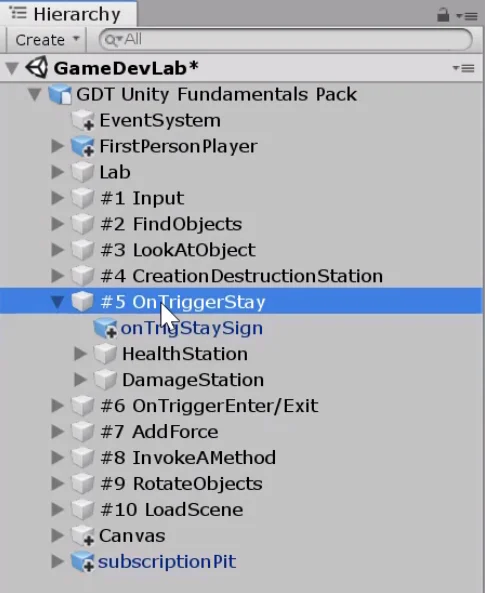
Fig. 1: GameDevLab OnTriggerStay Station.
All these objects are inside the emptyGameObject “#5 OnTriggerStay“. We have a regeneration station (HealthStation) and a damage station (DamageStation).
Fig. 2: Hierarchy of the scene. All elements of the station are in the GameObject #5 OnTriggerStay.
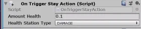
Both HealthStation and DamageStation are assigned the same script, “OnTriggerStayAction“.
Fig. 3: Script asignado a los GameObjects “HealthStation” y “DamageStation”.
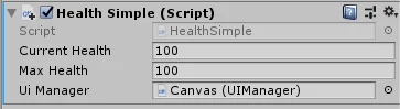
In the inspector we can modify the amount of health that gives or takes away through the float “amountHealth” and we can choose the type of station that is.
Fig. 4: The script allows us to choose whether the station does damage or regenerates.
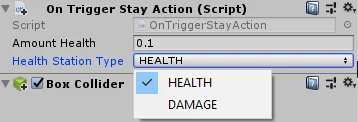
In order for the stations to be able to do their work, it is necessary for the player to have some kind of health system to affect. This is already solved in the GameDevLab. The GameObject FirstPersonPlayer is assigned a script called “HealthSimple” that has the necessary variables and methods to provide the player with a simple health system.
Fig. 5: Script asignado al GameObject FirstPersonPlayer.
Resolution
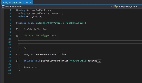
When opening the OnTriggerStayAction script for the first time we find what you see in figure 6. There is a defined region between comments where it is suggested to redefine the OnTriggerStay method.
Fig. 6: Script OnTriggerStayAction sin completar.
How does the OnTriggerStay method work?
This method is defined in the MonoBehaviour class, so it will be present by default in any new script we make.
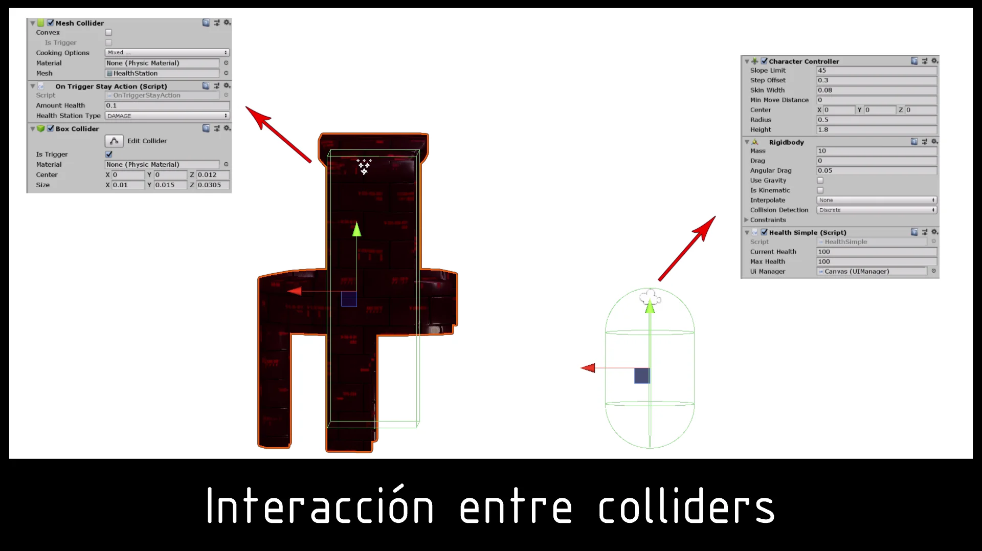
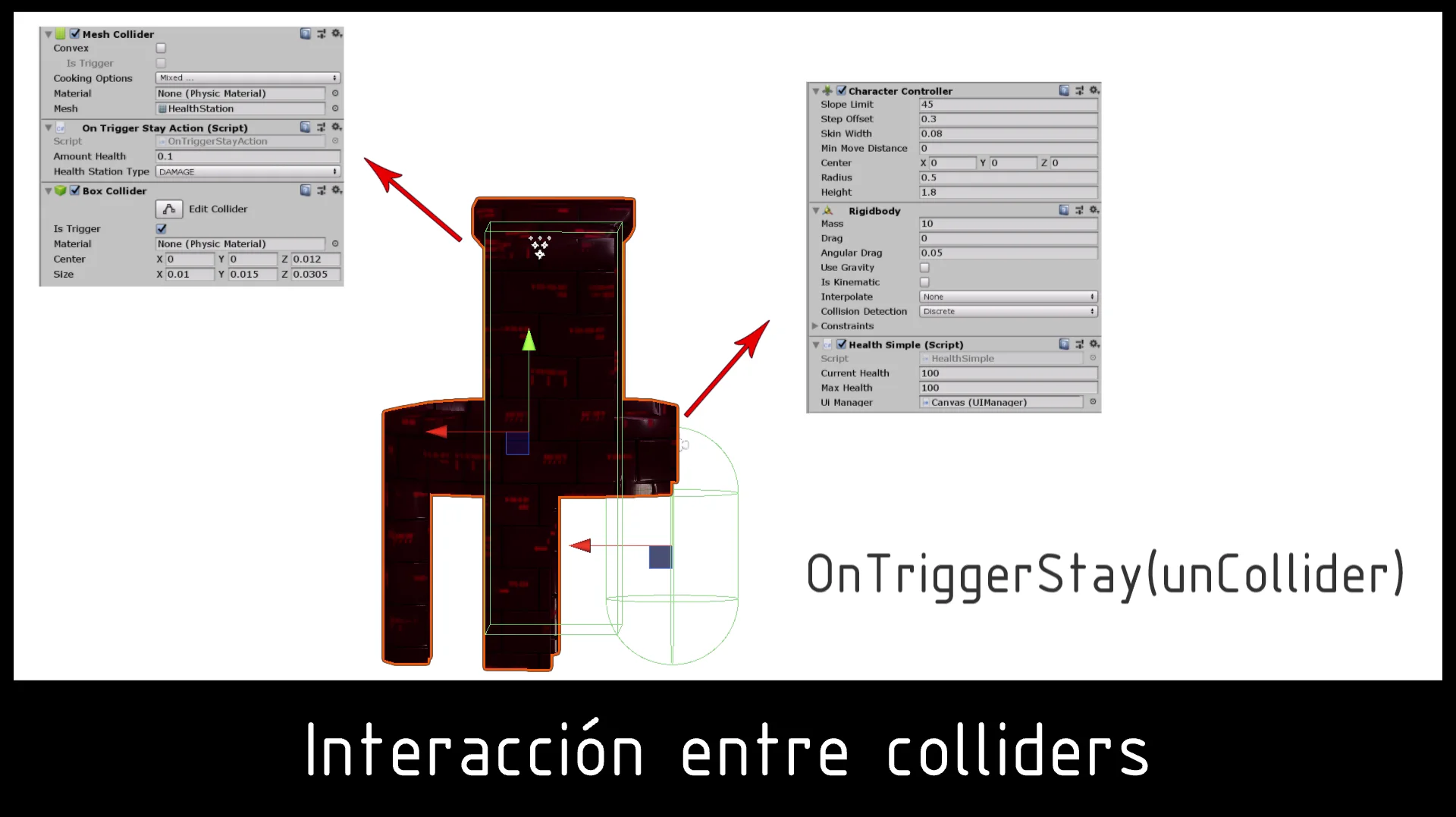
Runs automatically if a GameObject with Collider enters the region defined by another Collider who is in Trigger Mode. In addition, at least one of the two GameObjects must have a RigidBody component assigned to it.
Fig. 7: As long as the colliders do not touch, the OnTriggerStay method does not run.Fig. 8: Colliders are playing, so the OnTriggerStay method is executed.
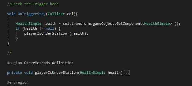
Figure 9 shows the resolution for the exercise.
Fig. 9: OnTriggerStayAction script resolution.
We redefine the OnTriggerStay method that receives as parameter the Collider that has come in contact with the trigger. We give the name “col” to the reference of this Collider.
What we have to do is first determine if the GameObject whose Collider came into contact has a health system to affect, we do this by getting the reference of the HealthSimple component that can be assigned to this GameObject.
If the GameObject has health system, we will have a component HealthSimple, otherwise our variable will have the value null. We use this as a condition in the if statement.
If the condition is true we execute the playerIsUnderTheStation method and pass as parameter the HealthSimple reference found in health.
With this we have solved the problem of video, from that point the component HealthSimple will handle the issue of health.
Fig. 10: Health value after a few seconds in the damage station.
Upon entering the damage station our health begins to decline, if it reaches zero value the scene is restarted.
Upon entering the regeneration station, health begins to increase until the maximum value is reached.
Fig. 11: Health value after a few seconds at the regeneration station.
Conclusion
The objective of this article and corresponding video is to study an application of the OnTriggerStay method, to understand how it works and then be able to apply it to any situation in which it may be useful.
There are many situations in which this method could serve, for example modeling the behavior of a pressure plate, make us affect an opposite force to gravity that makes us levitate if we are in a certain region. In short, this method is a useful tool that we have to understand.
It is not the point of this article to study the health system, but it is interesting to note that the stations are going to act on any GameObject that has the HealthSimple script, regardless of the player. This suggests that in our game we could have a single script that manages the health of any living being in our game and has properties common to all, as well as unique properties for each being. Creating this kind of solutions is what I find most interesting
On this occasion I bring a mix of one hour of environmental instrumental music to study or work on a project for an hour.
You can put this melody in the background while you do some homework, for example studying a language or doing a job. You can also use it to read a book for an hour.
The idea is to propose maximum concentration for the duration of the melody. At the end you will have dedicated an hour to your projects.
It may not seem like much of an hour for a project, but if we transform this practice into an everyday habit, after a few weeks the progress will be remarkable.
Video Purpose
I made this video mostly for my own use as a way of measuring time commitment.
Whether you want to read a book, study, write, make 3D models, practice a language, program or any other task, I intend to concentrate on maximum concentration for the duration of this video.
It depends on the occasion, but in general instrumental music is appropriate for me to isolate myself from the environment without losing concentration. That’s why I made the video have a low volume, but maybe too much.
We all have an hour a day if we gather free time, television time or perhaps a nap that was not necessary. It is true that it is often difficult to overcome tiredness after a day’s work, so you need willpower to start.
But if we manage to establish the habit of devoting one hour a day to a personal project, you can soon see the progress.
About Phrases
The phrases I chose are positive and motivating, which is what we need every morning to get the day off to a good start.
With the exception of the introduction, all phrases are attributed to recognized philosophers, writers, artists, scientists and brilliant minds, as well as proverbs and phrases of unknown origin.
I did not want to include the author because of possible errors in the sources of information. I believe that these phrases have a value of truth and wisdom regardless of to whom they are attributed.
Some names of authors are:
-Johann Wolfgang von Goethe
-René Descartes
-Martin Fierro
-Paulo Coehlo
-Albert Einstein
-Steve Jobs
-Charles Dickens
-Charles Chaplin
-Bill Gates
-Isaac Asimov
-Bruce Lee
-Henry Ford
-Pablo Picasso
About music
At all times you can hear in the background the sound captured somewhere in Argentinian Patagonia, far away from the city.
Various birds such as sparrows, pigeons and parrots, as well as roosters and geese.
Children playing, dogs, perhaps a light wind and the sound of leaves.
As far as possible I tried to suppress the sound of vehicles and noises that do not come from nature.
The songs you hear are a mix taken from the YouTube library for creators, some names are:
La música se encuentra limitada a un tope de decibeles, de modo que se puede ajustar un determinado volumen esperando que se mantenga a ese nivel en todo momento.
Introduction
In this article we are going to see what a linear function is, its mathematical expression, its characteristics, how to graph it in the Cartesian plane and what it can be useful for in the development of videogames with examples in Unity.
Mathematical expression of a linear function
A linear function is a polynomial function whose expression is:
f (X) = a . X + b
It is commonly read “f of x”, being X the independent variable, a and b constant real numbers.
Analyzing the expression we see that given any value of X, we first multiply it by a and then add b. The result of all that operation will be the value of f (X).
Characteristics of a linear function
Domain
The domain is the range of allowable values for the independent variable, commonly referred to as X.
In the case of the linear function, the domain is the set of real numbers.
In other words we can choose any value of X belonging to the set of real numbers and we will find its corresponding value f (X).
Graph in the Cartesian plane of a linear function
The graph of f (X) in the Cartesian plane is a straight line. We can easily draw it by finding two points of the function and then using a ruler, draw the line that joins the two points.
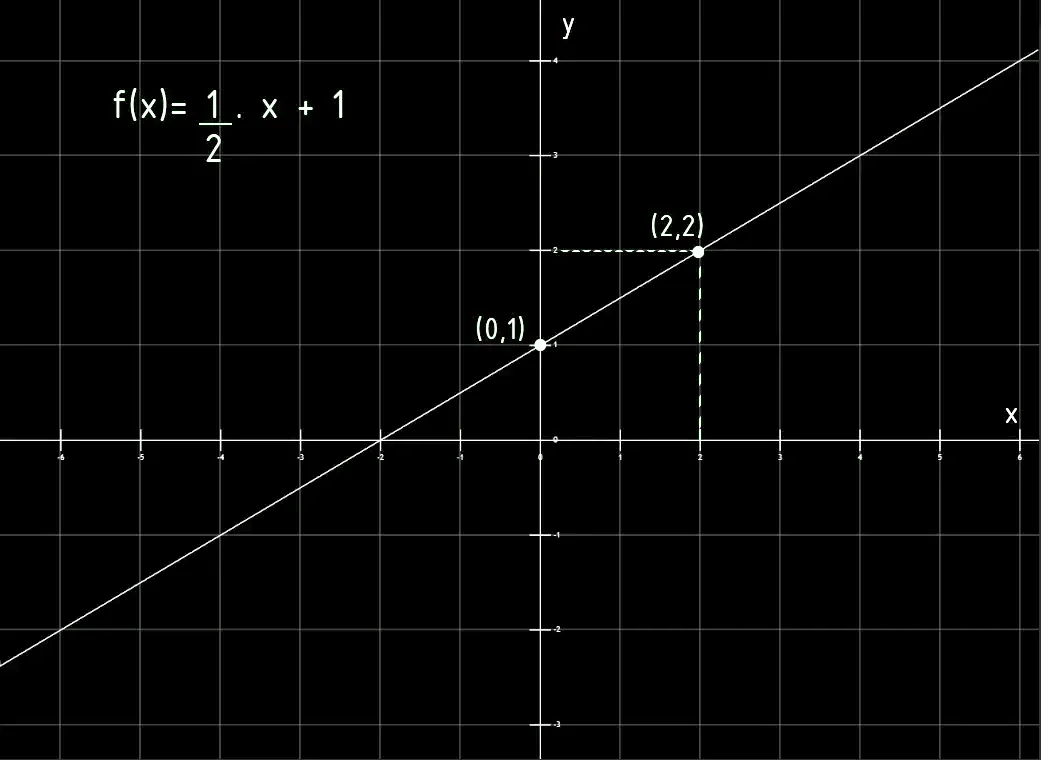
We can easily find one of these points by considering X = 0.
The second point can be found by choosing a different value for X and making calculations, for example for the function in figure 1, if we consider X = 2, the result of f (X) is equal to 2.
Fig. 1: Example of the graph of a linear function.
Ordinate of the origin
It is the value of the function when X = 0, graphically it is the point where the function cuts off the vertical axis known as the ordinate axis. This point is known as the ordinate to the origin.
In the graph of figure 1 we see that the ordinate to the origin is the point (0,1).
Abscissa of the origin
Analogously to the previous case, the abscissa of the origin is the point at which the function intersects the horizontal axis or abscissa axis. At this point Y = 0.
A linear function may have no abscissa at the origin if it is a line parallel to the x-axis and displaced.
In the graph of figure 1 we see that the abscissa of the origin is the point (-2,0).
Slope of a linear function
The term that multiplies X is known as slope and is the one that establishes how much the function changes when the variable X changes by one unit.
If we only have the graph of a linear function, we can calculate the slope as the tangent of the angle that forms the line with the horizontal axis. We can also find the slope using the Pythagorean Theorem.
Parallel lines
Two straight lines are parallel if they have the same slope.
Example of two parallel lines:
f (X) = 2 . X – 1
g (X) = 2 . X + 3
Perpendicular lines
Two straight lines are perpendicular if the slope of one of them is equal to inverting the slope of the other and multiplying it by -1.
Example of two perpendicular lines:
f (X) = 3 . X + 2
g (X) = – ( 1/3 ) . X + 5
Some examples in Unity of linear function
The linear function is one of the most useful mathematical functions and its field of application is very varied. Let’s give some examples of possible applications.
Represent trajectories
The most basic thing I can think of is for objects to move in a straight path, which can be described as a linear function.
For example in figure 2 we see a scene in Unity in which the spheres are describing a trajectory that is described as their position in x is equal to their position in y.
Fig. 2: The spheres are advancing in the positive direction of the X-axis, their height Y is determined by the calculation of function y = x.
The same concept and with different combinations of planes can be applied to other cases such as vehicle movements, projectile trajectories, etc.
Let’s suppose that we have any two parameters, for example the position of the player on the X axis and the rotation of a mechanism with respect to one of its axes.
Let’s also say that we would like these parameters to be connected in some way, that is to say that the rotation of the mechanism will depend on the position of the player.
We can then establish a linear relationship between these two parameters, for example we could say that the rotation of the mechanism with respect to its z-axis is equal to half the value of the player’s position on the x-axis plus five units.
With this we can relate these two parameters through a linear function.
Implement linear magnitudes in our game
In physics there are many linear magnitudes that we might be interested in implementing in our game. An example of this can be the uniform rectilinear movement, in which we have a direction of movement established and the position will be defined by a linear function in which the slope of the line is the velocity of the object and the ordinate to the origin is the initial position.
In the case of Ohm’s Law for example, if we have a circuit with a source connected to a resistance, the circulating current is equal to the voltage of the source divided the resistance, this is nothing other than a linear function with the form i = v / R.
The potential gravitational energy of an object is a linear function of its height above ground.
There are several physical phenomena that are characterized by linear behavior and that we might be interested in implementing.
Conclusion
The linear function is one of the most basic functions but also one of the most useful.
The graph in the Cartesian plane corresponds to a line in which we can identify a slope and an ordinate to the origin, point in which the line cuts to the vertical axis or abscissa.
We can use it to establish linear relationships between different parameters of our game and represent physical phenomena of linear character.
Introduction
In this article we see how to CALL FUNCTIONS and READ VARIABLES that are defined in a different script in Unity. This is especially important to create object-oriented solutions, because being able to access other scripts allows us to create scripts that solve specific problems and work with other scripts to achieve a bigger result, separating responsibility, increasing abstraction. In addition you will also find two videos about calling functions and reading variables from another script in Unity.
All the IMPORTANT information is summarized in the following TUTORIAL FROM MY YOUTUBE CHANNEL
Interaction between scripts – A couple things to keep in mind
Let’s look at a list of items to keep in mind to understand the basis behind the interaction between scripts.
About the Scripts
In this case we are going to see an example in Unity, therefore the two Scripts we are going to use will be an extension of the MonoBehaviour class. This, in practical terms, means that when the game starts, a “Start” function will be executed and also in each frame of the game an “Update” method will be automatically executed.
About the execution of Scripts
In order to execute the code that we will include in our scripts, those scripts must be assigned to at least one “GameObject” in the hierarchy of the scene we will run. In programming, there must exist an Instance of the class defined in the Script.
Instances of a classes
When we add the same Script to two different GameObjects we are creating two separate instances of the class, i.e. two objects that are going to be similar because they come from the same class, but their internal state will not necessarily be the same all the time.
Having the reference of an object
This is one of the key points to pay attention to and try to understand in depth.
Objects in programming are instances of a certain class and in order to access its functionality, that is to say read its public parameters or execute its public functions, we must have the reference of the object we need to use, in other words find the object among all the other objects that exist in the program.
The Dot Operator
The dot operator in several programming languages allows us to access the public fields and methods from an object. In other words, if we have the object reference, we can apply the dot operator to it in order to execute any of its public methods or read and write any of its public fields.
Practical example of Interaction between Scripts in C# – Unity
Previous Steps
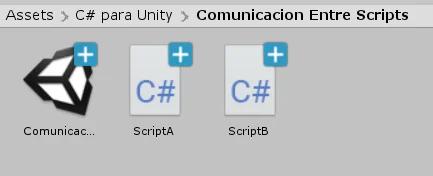
In any Unity project we create two Scripts, ScriptA and ScriptB, in the first one we define the function that will be executed from the second Script.
Fig. 1: We create two scripts called ScriptA and ScriptB.
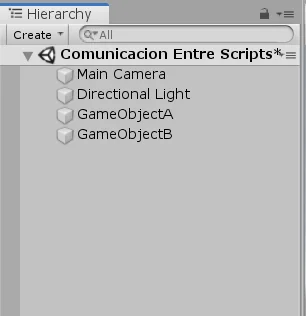
In the hierarchy we are going to create two empty GameObjects to be able to create instances of both Scripts.
Fig. 2: Create two Empty GameObjects in the hierarchy to contain both Scripts.
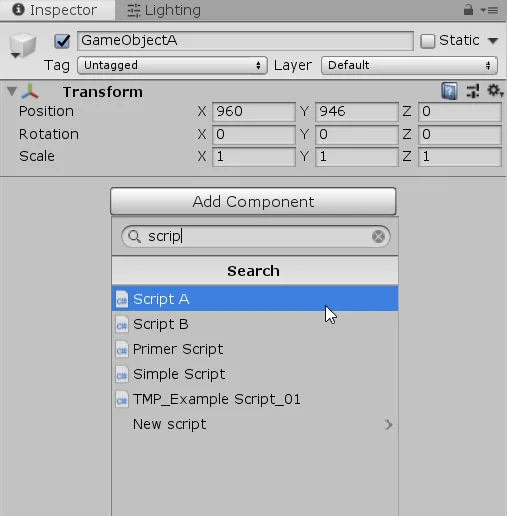
In GameObjectA we add the ScriptA as component and in GameObjectB the ScriptB. We can do this from the inspector with the “Add Component” button or by dragging the script to the inspector of the GameObject.
Fig. 3: Select object A and in the inspector, using Add Component, add ScriptA to its components.
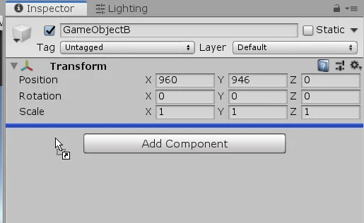
Fig. 4: Another way to add components is to drag them directly into the GameObject inspector.
Code inside the Scripts
Let’s write the instructions we’ll use to perform the interaction between Scripts.
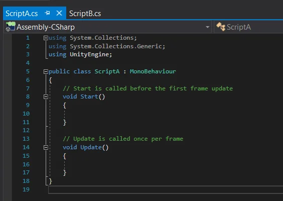
When you create a new Script in Unity, it will come with some functions predefined, as you can see in figure 5. The “Start” and “Update” method, which will be automatically executed if the Script is assigned to at least one GameObject from the hierarchy.
Fig. 5: We open both Scripts in some editor. We can see some code already written.
Functions and Variables from “ScriptA”
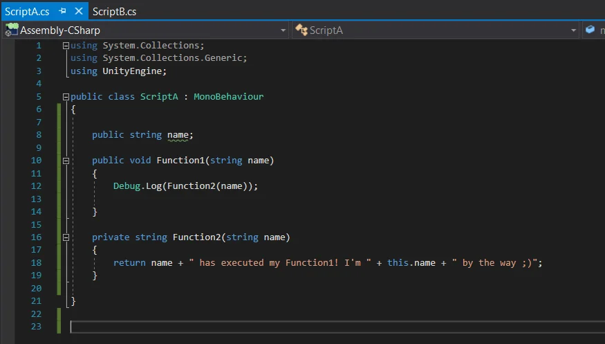
In the first Script we are going to write the following code:
Fig. 6: Fields and methods belonging to Script A.
A public string called “name” that will help us identify which instance it is.
Two methods, one called “Function1” and the other “Function2“, the first function we will define it as public and the second private, lines 10 and 16 respectively from figure 6.
We will be able to access the “Function1” method through the dot operator because it was defined with public visibility. , as it’s defined as public.
As we can see in figure 6, “Function1” prints in console the result of the execution of “Function2“. This method returns a text that will allow us to see who is the object that is executing the “Function1” method and which instance of the ScriptA class it is.
Functions and Variables from “ScriptB”
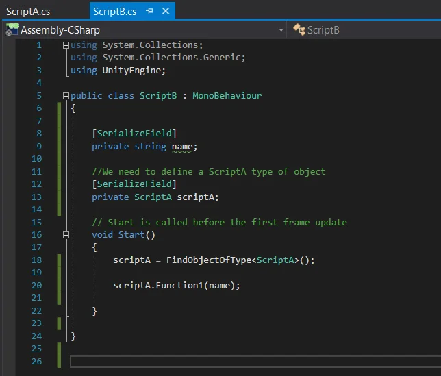
The “ScriptB” script will be the one that calls the function defined in the other Script A. In figure 7 we see the instructions defined in the “ScriptB” script.
Fig. 7: Fields and methods belonging to Script B.
We define a string to assign a name and know which instance it is.
To be able to execute functions defined in another Script we must have the reference of the instance of that class. So let’s define a ScriptA type variable and name it “scriptA” (first letter with lowercase), as we see in line 13 of figure 7.
Here we only have half of the work done, we declared the “A” variable inside “B”, but this variable is empty (a null variable) and will remain empty unless we do something about it.
To find the reference of an object in a Script there are several ways, in this case I will use a function calle “FindObjectOfType<T>” where “T” is the type of the variable we want to find. This function will search in the hierarchy an object of the indicated type and return the reference of that object if it founds it. See line 18 of figure 7.
Now that we have the reference of the “A” object, inside “B” we can execute the “Function1” function that is defined inside the A Script. Line 20 from figure 7).
Dot Operator
As mentioned before, the dot operator will allow us to access all the fields and public methods defined within the class.
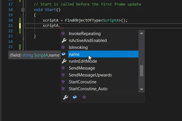
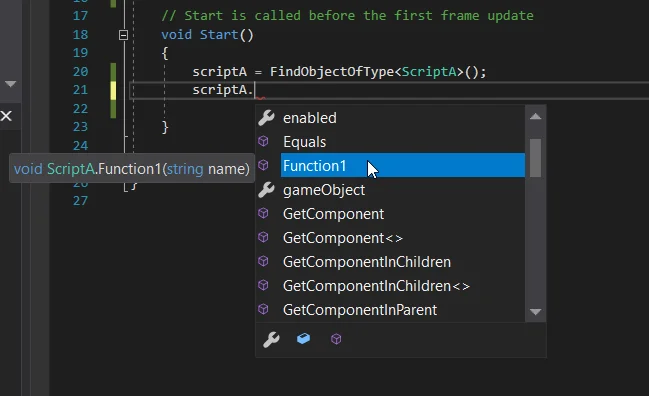
In figures 8 and 9 we see that using the reference of the ScriptA-type object followed by a dot, we can see the list of fields and methods that are available to use.
In figure 8 we see the “name” variable that was the public string defined inside “ScriptA” and in figure 9 we see the “Function1” method, also defined as public. We can’t see the “Function2” method because it was declared as private.
Fig. 8: The dot operator allows us to read and write the “name” field, which is a string defined as public.
Fig. 9: The point operator allows us to execute the “Function1” method defined as public.
First exectution test
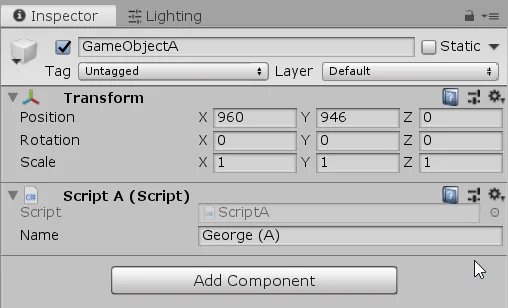
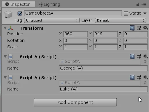
Before enter in the Play mode, we select GameObjects “A” and “B” from the hierarchy and write names in the “name” fields to be able to analyze the execution of our code.
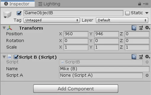
The “ScriptA” instance will be called “George (A)” and the “ScriptB” instance will be called “Mike (B)“, as we see in figures 10 and 11.
Fig. 10: In the GameObjectA inspector, we put a name to know that it is that instance of the Script A class.
Fig. 11: In the GameObjectB inspector, we put a name to know that it is that instance of the Script B class.
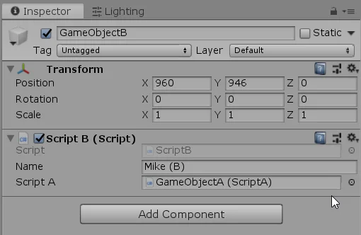
When entering in the Play mode we see in the inspector of GameObjectB that the “ScriptA” field shows an object (unlike figure 11 where it said “none”). This means that the “ScriptB” was able to find the “ScriptA” reference.
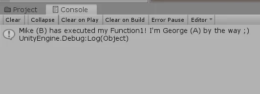
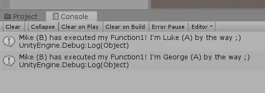
Figure 13 shows the on-screen message, printed by the ScriptA Function1 method, which was called from the ScriptB.
The message says: “Mike(B) has executed my Function1. I’m George(A), by the way.
Fig. 12: When running the game, the ScriptA object reference is found due to the FindObjectOfType<> instruction.
Fig. 13: This message is printed because a method defined in ScriptA is executed from the ScriptB.
Second execution test
Let’s go a little deeper into the concept of programming object as an instance of a class.
Choose GameObjectA from the hierarchy and add a second instance of the ScriptA class using the “Add Component” or drag and drop button.
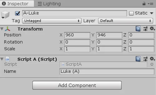
This second instance will be called “Luke (A)“, in figure 14 we see both instances of the class.
Fig. 14: A second instance of the ScriptA class is added to the GameObjectA with a different name.
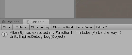
When running the game as it is, we see in the console that Mike (B) has executed the Function1 method of Luke (A), see figure 15.
What has happened here is that the “FindObjectOfType<>” function in line 18 of figure 7, has found a different reference of a ScriptA type object than before, the “name” variable from this references is “Luke (A)“. A different instance of the same class as the one that has the text “George (A)” in its “name” variable.
Fig. 15: When running the game we now see that the Function1 method of the instance called Luke is being executed.
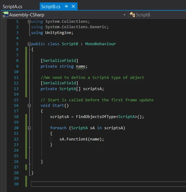
Now lets modify the code in “ScriptB” so that it is able to find all the “ScriptA” references in the scene and execute the “Function1” method of each one of them.
Fig. 16: We modify the ScriptB in this way so that it executes the functions of the two instances of ScriptsA.
In the object declaration we have now defined an array (or vector) of “ScriptA” type objects (line 13 figure 16), this means that we will be able to save several references of ScriptsA objects.
In line 18 of figure 16 the change is rather subtle, instead of running the “FindObjectOfType<T>” function we use “FindObjectsOfType<T>“, this other function returns all the references of the indicated “T” type that is able to find in the hierarchy.
The last thing we do is go through all the elements of the array using a foreach loop and we execute the “Function1” method to all of them, as can be seen in lines 20 to 23 of figure 16.
Fig. 17: When running the game we see that the two references of the ScriptA objects are found and we have them stored in the array.
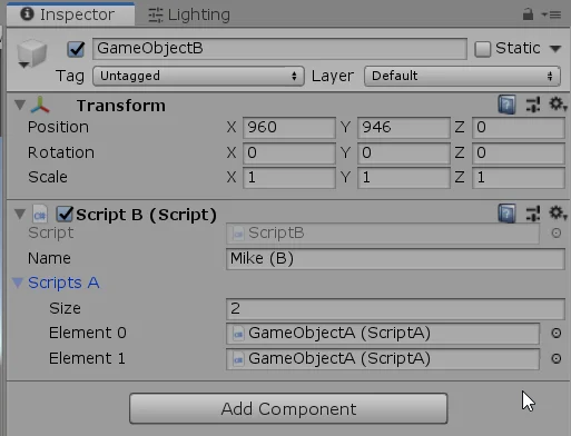
When entering again in the Play Mode, we see that now in the GameObjectB inspector we have the “ScriptA” object references (figure 17) inside an array of size 2.
And now in the console appear two messages, the first corresponds to the execution of Luke’s “Function1” method and the second to the execution of George’s “Function2” method.
Fig. 18: In the console we see that the Function1 methods of each ScriptA object are executed.
Third execution test
We are going to modify the ScriptB again to see another way to obtain the references of the objects and thus to be able to call their functions from another Script.
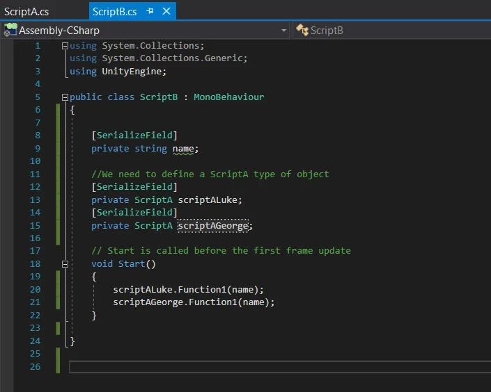
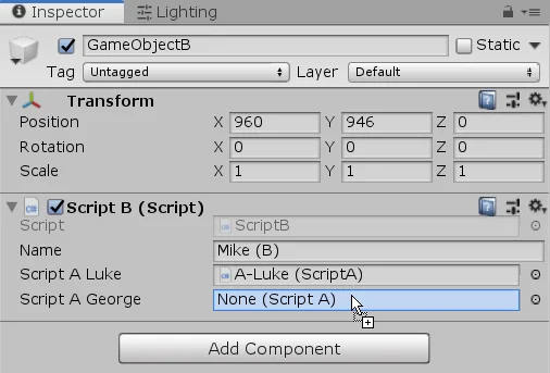
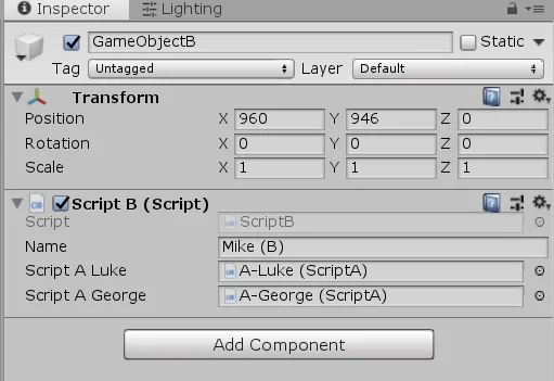
In this case, in the “ScriptB“, we are going to declare two serialized “ScriptA” objects (they can also be public, the idea is that they appear in the inspector). These objects will be called “scriptALuke” and “ScriptAGeorge“.
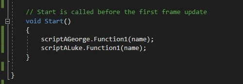
Then in the Start method we are going to execute the “Function1” methods directly using these objects. In this case it is not necessary to find the references through code since we will assign them directly in the inspector.
The modified “ScriptB” is shown below.
Fig. 19: We modify the ScriptB in this way to try another way of having the reference of the objects.
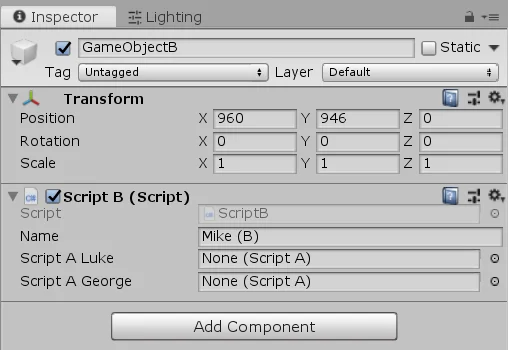
In the inspector we can see the new fields for “ScriptA” objects (figure 20).
Fig. 20: In the inspector we have fields for two ScriptA objects.
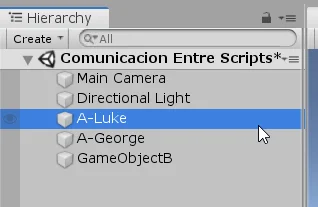
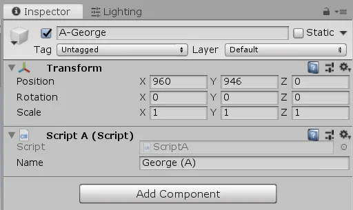
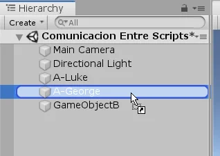
We will modify a little the GameObjects of the hierarchy, we will have an Empty GameObject called A-Luke and another called A-George.
Fig. 21: Instead of the GameObjectA we will have two empty GameObjects for each instance of the ScriptA class.
In each GameObject we assign the ScriptA component and complete the corresponding name, see figures 22 and 23.
Fig. 22: In the GameObject A-Luke we add the ScriptA component and enter the corresponding name.
Fig. 23: In the GameObject A-George we add the ScriptA component and enter the corresponding name.
Now let’s take the GameObjects from the hierarchy and assign them in the corresponding fields of the “ScriptB”
Fig. 24: With these GameObjects we will drag and drop in the ScriptB fields.
In figures 25 and 26 we see that the references have been assigned manually, this means that we can execute the “Function1” methods from each instance.
Fig. 25: We can assign the GameObject directly to the corresponding field whenever there is such an object among its components.
Fig. 26: The references of both ScriptA objects have been assigned to the corresponding fields.
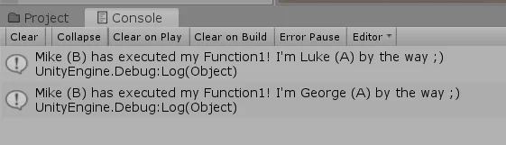
In console we see that the messages are printed due to the execution of “Function1” method on both instances.
Fig. 27: When running the game we see that the Function1 methods of both instances are executed.
Before finishing I would like to change the order of execution of the Function1 methods in the ScriptB, as seen in figure 28.
Fig. 28: Reverse the order of the instructions and perform another test.
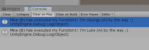
When we do this and enter in the Play Mode again we see that the messages on the console switch places, figure 29.
Fig. 29: We see that the messages change the order of appearance in the console.
Conclusion
We have seen how to call functions that are defined in other Scripts. This is only possible if the functions are declared with publicvisibility, this allows the access from external contexts.
In addition we must have the reference of the object that contains that method to execute, this can be achieved in several ways, in this article we saw three ways to do it. It’s important to understand the concept of instances in programming, it can be two or more instances of the same class and therefore multiple objects with the same function defined but the result of the execution of that function on each instance could be different.
Understand in depth the concept of object in programming, which is the instance of a class and the fact that in order to access another object we must have the reference of that object, allow us to build more complex solutions, separating responsibility, increasing the abstraction of our solutions.
Introduction
In this article we’re going to look at how to create and destroy GameObjects at runtime. Achieving this is very important for creating games, because it allows us to place objects when and where we want and then destroy them.
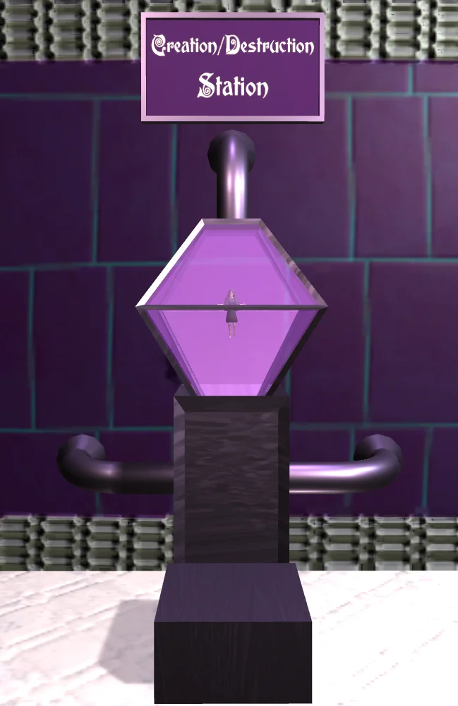
In this challenge we are going to use the Creation/Destruction station shown in figure 1, to make a small Lucy appear and disappear cyclically while the game is running.
Fig. 1: Creation Destruction Station of the GameDevLab.
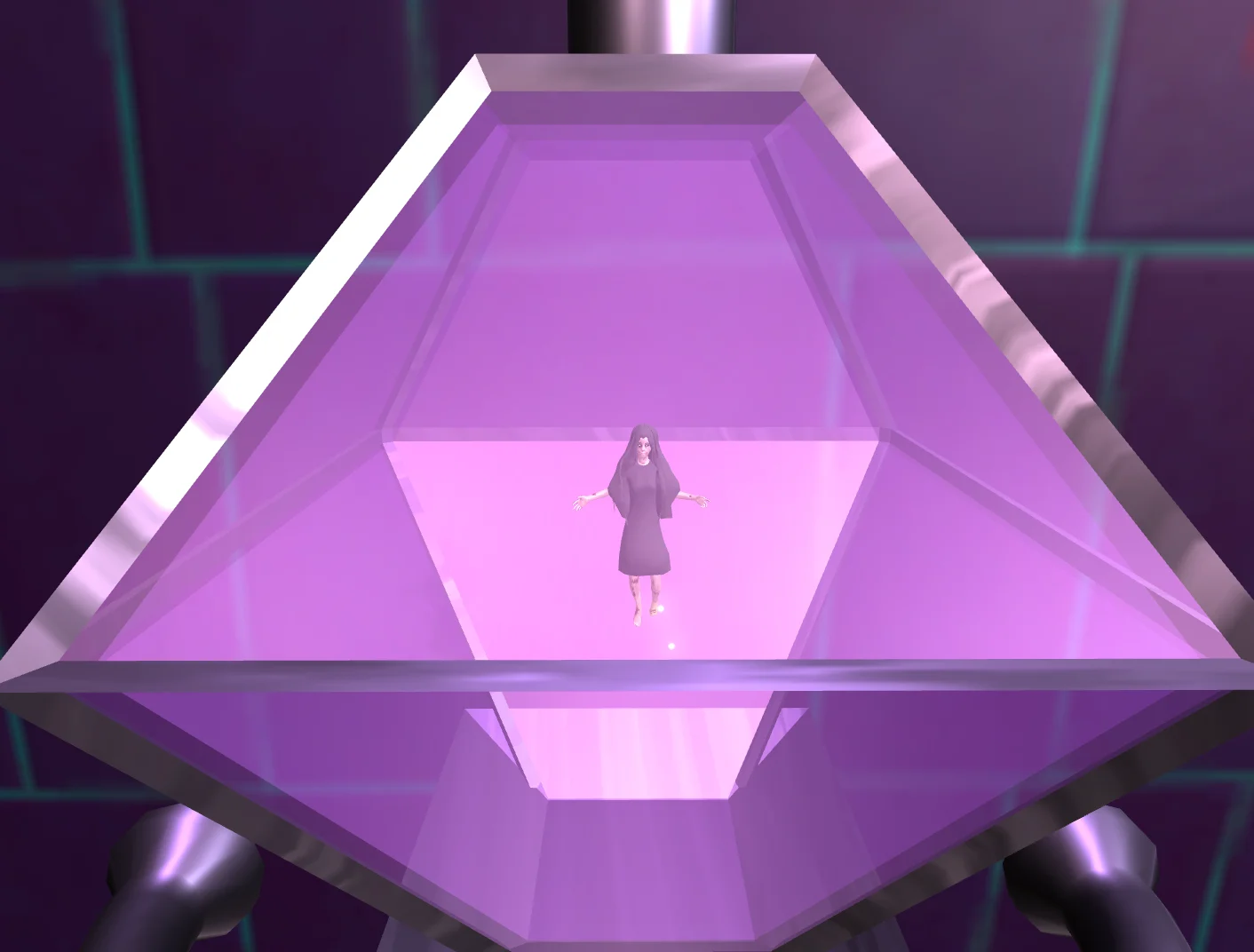
Fig. 2: Creation Destruction Station of the GameDevLab. Lucy appears for a few seconds.
Fig. 3: Creation Destruction Station of the GameDevLab. Lucy disappears.
Figures 2 and 3 illustrate the cycle of Lucy’s appearance and disappearance.
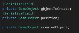
Fig. 4: Fields of the CreationDestruction Script corresponding to the challenge of video 4 of the Fundamental Series.
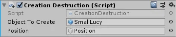
Figures 1 and 2 show the fields and components in the “CreationDestruction” Script inspector.
Fig. 5: The GameObject “#4 Creation Destruction” is assigned the Script Creation Destruction. This is seen in the inspector.
The challenge is to complete the createObject() and destroyObject() methods of the Script.
Solving this exercise
Creating the object
For the creation of the object we are going to use the Instantiate method, this method is defined in the MonoBehaviour class that by default is the super class or parent class of every new Script that we make in Unity.
At the moment I don’t have enough articles or videos about object-oriented programming to clarify the super classes, I know I will eventually do them, but for now if you want to know more research the topic Heritage in object-oriented programming.
The Instantiate method has more than ten variants, but in all of them we basically need two things: the object we are going to create and where in the space we are going to put it.
In this case the object that we are going to create we indicate it using the prefab SmallLucy that is in the folder Internal Use, this prefab we place it in the space Object To Create in the inspector, as it is observed in the figure 5.
To indicate the point of the space where we are going to place the new object we are going to use a GameObject called Position that is in the hierarchy. We also assign it in the inspector (figure 5).
We are going to use a variant of the Instantiate method that will create the object and place it in the hierarchy as a child of the GameObject we indicate. This means that our object will appear in the position of the parent GameObject (Position) plus the own displacement that SmallLucy has (in this case SmallLucy is in the origin so its displacement is zero).
I know that the paragraph above is somewhat confusing, but later I would like to make a video and article about global and local coordinates in order to explain this more clearly. For now, let’s move on. We write the following line in the createObject method:
First of all createdObject is an auxiliary GameObject type object (see figure 4) that we define to save the reference of the new object we are going to create. This is very important because otherwise later we won’t know which object we have to destroy.
The Instantiate method will return a GameObject type object (the new object) and with the equal sign we assign it to createdObject.
In parentheses indicate the two parameters separated by a comma. The first parameter is the object to create and the second is the Transform component of the GameObject Position
Fig. 6: Methods defined in the CreationDestruction Script corresponding to the challenge of video 4 of the Fundamental Series.
Destruction of the object
To destroy the object we use the Destroy method (which is defined in the MonoBehaviour class) and give it as a parameter the reference of the object we have saved in the createdObject field. We write this in the destroyObject method.
Cyclic behaviour
We want Lucy to appear and disappear continuously in the Creation Destruction station, so we have to run the createObject method. Then wait a few seconds and call the destroyObject method, then wait and call the create method again.
We did this first by calling the createObject method from Start, so that when you start the game, Lucy appears. Then at the end of the create method we use Invoke to call the destroyObject method after two seconds. We do the same thing at the end of the destroyObject method, we use Invoke to call the create method. We can see this in figure 6.
Conclusion
We have managed to make new objects appear on the stage at runtime, that is, while the game is running, this is no small thing, understanding this we can achieve many things.
To create a new object in the world we basically need a copy of the object to create, this we achieve with a prefab. And we have to know exactly where to place it, this can be achieved in many ways, that’s why the Instantiate method has so many variants.
If we want to destroy a GameObject of the hierarchy we need to know what it is, so it is very important the object reference, if we create the object without assigning it to any field, the object will be in the hierarchy but we can not do anything with it unless we find it again.
Introduction
In this article we see what is a method in programming, what they are for and how to declare them in C# language with concrete examples in a game project in Unity.
¿What is a Method in Programming?
In this context a method is a function that has a set of instructions defined within it.
The method has a name to identify it.
We can make it require different type of input data to run. And we can make the method return data as a result.
When we need to execute the instructions contained in the method, we do so simply by using its name.
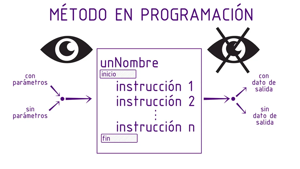
Fig. 1: Scheme illustrating the basic properties of a method.
Modularity
In figure 1 we see the method represented as a box, in which the name of the method appears as title, the beginning and end of the method is specified and the set of instructions is within this region.
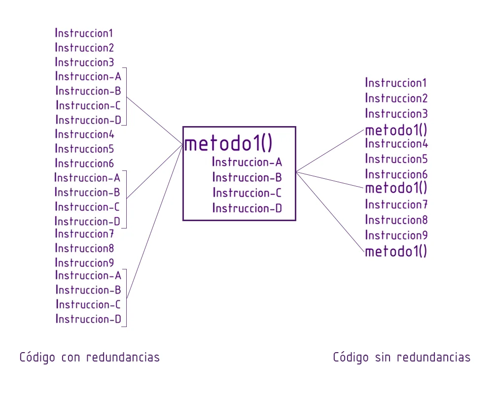
To understand what modularization is all about, see figure 2. On the left we see a long list of programming instructions.
Now within that list are a number of instructions that are used in more than one place, instructions A, B, C, and D. Let’s say these instructions perform a particular task and are always executed together.
Fig. 2: On the left a code with repeated instructions. To the right the same code with modules.
Suppose we now have to make changes to those instructions (for example to improve the way it solves the task or add functionality), what happens is that we have to identify all the regions where those instructions are.
It would be great if we could change things in one place and the changes apply to all regions where these instructions are used, wouldn’t it?
This is precisely what we achieve with the methods, they allow us to group sets of instructions in an independent module that can be called when necessary, as we can see on the right in figure 2, the instructions were now replaced by the name of the method.
Input and Output parameters
In figure 1 there are arrows that go in and out of the method. With this I try to represent the input and output of parameters.
We can make our method require input parameters, which we use inside to make calculations or perform any type of task.
In addition we can make the execution of the method produce an output data, which we will use outside the method.
Public and private methods – Visibility
Finally in figure 1 we see a normal eye and another crossed out eye. This represents the visibility that the method will have, which is an object-oriented programming topic, we are not going to delve into this article but in principle let’s say that we can have public methods and private methods.
Public methods can be executed from other Scripts for example, or we can execute them from a component in the hierarchy in Unity, for example a button.
Private methods will not be accessible from contexts external to the script where it is defined.
Syntax
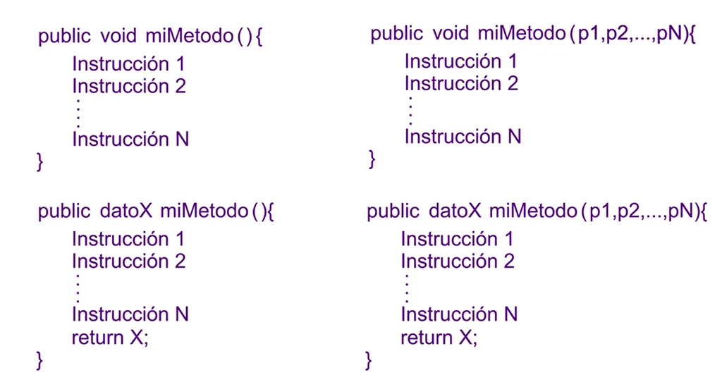
The syntax is the set of rules established in a language to write the code, in figure 3 we see possible syntax of a method,
Fig. 3: Different combinations of input and output parameters for the methods.
This syntax can be applied to C# and Java, one detail is that all methods are public, but we could replace the word “public” with “private” and the syntax would be correct.
Declaration of a method
Example 1
Let’s analyze the method that is above to the left in figure 3.
We have the structure of a public method that does not require parameters and does not return parameters.
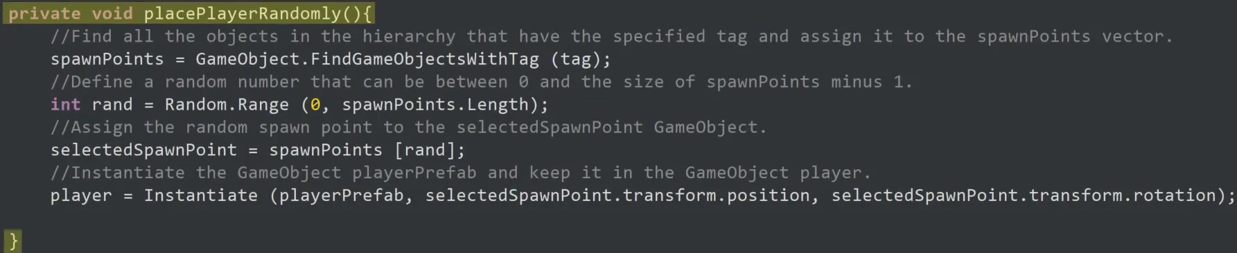
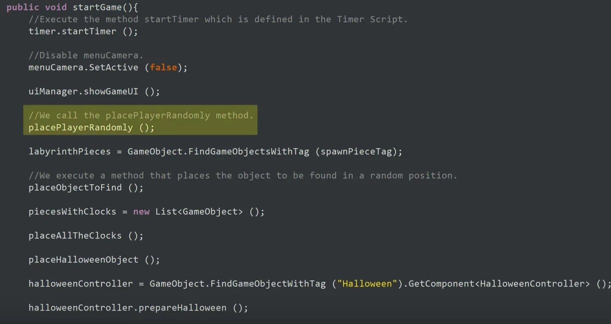
This structure can be found for example in the script “GameControl” of the project My first game in Unity.
Fig. 4: Method belonging to the script: “GameControl”.
We observe that it has been declared as private instead of public, then we find the word “void” with which we indicate that this method will not return parameters.
Then the name of the method: “placePlayerRandomly”.
We open and close parentheses indicating that this method does not need parameters.
The beginning and end of the method is indicated using keys. Inside will be all method instructions.
Invocation or call to the Method
Once the method is defined we can make it run from any part of the script, we can even invoke it from other scripts.
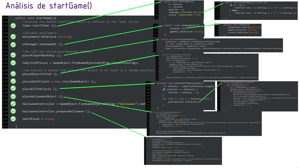
The following figure shows the invocation of the “placePlayerRandomly” method in the “startGame” method of the same “GameControl” script.
Fig. 5: In yellow: invocation of the “placePlayerRandomly” method.
To invoke this method we write its name and open and close parentheses, we close the instruction with semicolon. By doing this we are achieving that all the instructions of the method are executed.
Notice how the names of the methods are already helping us to understand what is going on. At the beginning of the game the character should be placed randomly.
From the “startGame” point of view the “placePlayerRandomly” method is a function that does everything necessary to place the character randomly. The startGame method doesn’t know exactly how it does it but it doesn’t care, because placePlayerRandomly does its job well.
Example 2
In the upper right corner of figure 3 we have the structure of a method that does not return parameters but does require them to work.
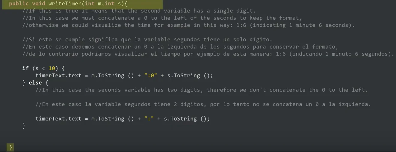
Fig. 6: UIManager script “writeTimer” method.
This method requires two parameters to work: an integer value m that will indicate the minutes of the timer and an integer value s that will indicate the seconds.
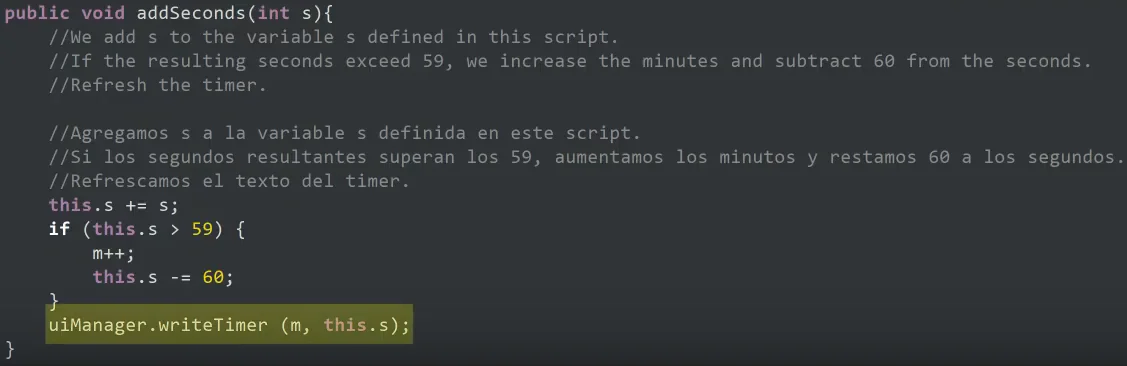
Fig. 7: Invocation of the “writeTimer” method from the “Timer” script.
The invocation of this method occurs in several places of the code, in particular the method “addSeconds” belonging to the Script “Timer”, this method receives as parameters an integer “s” that represents the amount of seconds that must be added to the timer because the character grabbed one of the clocks that are on the stage.
The “addSeconds” method does some operations with the “s” variable to update the time and finally executes the “writeTimer” method that shows the new time values on screen.
Two observations: the first is that since we are executing the method from another Script it is necessary to add “uiManager”. (pay attention to the dot) before writing the name of the method “writeTimer”.
The second is that parameters are entered within parentheses and separated by comma.
In both scripts I used confusing names (m and s) on purpose so that in the future, when we talk about contexts, we can analyze them.
Example 3
We move on to methods that return parameters.
The following example corresponds to the structure illustrated in the lower left corner of figure 3, a method that returns data and does not require parameters to function.
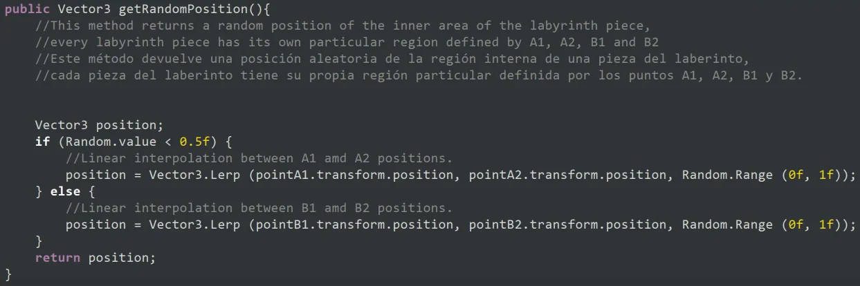
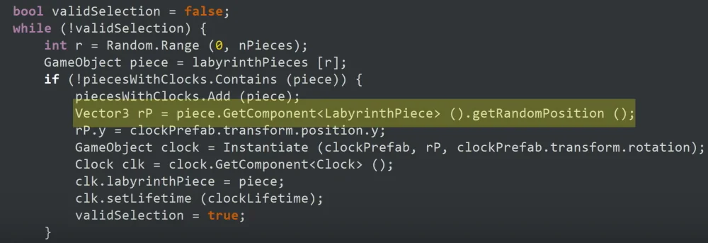
Fig. 8: “getRandomPosition” method of the “LabyrinthPiece” script.
The data returned by this method is a “Vector3” and is indicated in the declaration, after the word “public”. Notice that the first line that is not a comment says: “Vector3 position;”, there we are declaring a Vector3 that we call “position”, then we do some calculations and at the end of the method we write: “return position;” indicating that we return that Vector3.
This method returns a Vector3 (component x,y,z) that represents a random position belonging to the inside of a given piece of labyrinth. In this way we can use this position to place the pedestal or clocks without worrying for example that they are embedded in a wall.
Fig. 9: Invocation of the “getRandomPosition” method.
It is not easy to understand the instruction highlighted in figure 9. For now let’s look at two things, the first is that we make a call to the “getRandomPosition” method using its name (as seen at the end of the instruction). The second is that the result of that invocation is a Vector3 data, therefore, using the equal sign, we assign it to the “rP” data that is defined as Vector3.
Example 4
The last example corresponds to the structure illustrated in the lower right corner of figure 3, a method that returns data and requires parameters to function.
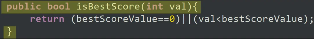
Fig. 10: Declaration of the “isBestScore” method.
We see that in the declaration we say that the method “isBestScore” returns a bool type data and requires an int type data that we call “val”.
The “isBestScore” method returns a variable that can be true or false. The utility of this method is that we use it to ask if the score obtained in the game (val) is better than the one saved so far (bestScoreValue).
Fig. 11: Invocation of the “isBestScore” method.
This method is invoked in the “gameWon” method. Since the method returns a bool value, we can use it directly as an argument for an if statement, because “score.isBestScore(time)” is equivalent to having a true or false value.
StartGame() Mehotd from GameControl
To finish figure 12, the “startGame” method is observed along with the other methods it invokes.
In addition to grouping instructions, a method must have a well-established purpose that is consistent with the name we gave it, so that we can quickly know what its function is and what type of instructions it may contain.
Fig. 12: Declaration of the “isBestScore” method.
For example, the “startGame” method is in charge of coordinating a series of actions to start the game, but it is not he who directly performs these actions, but invokes other methods with more specific tasks.
This makes it easier for us to make changes to the code and debug errors.
Conclusion
Methods are a powerful tool for developing specific, efficient, reusable and sustainable solutions.
Sustainable in time because at all stages of development we will have to make changes, so we have to be able to remember or quickly understand how our code works.
This is achieved by using descriptive names, documenting our code, and applying the object-oriented paradigm.
This website uses cookies to improve your experience. We'll assume you're ok with this, but you can opt-out if you wish. Cookie settingsACCEPT
Privacy & Cookies Policy
Privacy Overview
This website uses cookies to improve your experience while you navigate through the website. Out of these cookies, the cookies that are categorized as necessary are stored on your browser as they are as essential for the working of basic functionalities of the website. We also use third-party cookies that help us analyze and understand how you use this website. These cookies will be stored in your browser only with your consent. You also have the option to opt-out of these cookies. But opting out of some of these cookies may have an effect on your browsing experience.
Necessary cookies are absolutely essential for the website to function properly. This category only includes cookies that ensures basic functionalities and security features of the website. These cookies do not store any personal information.


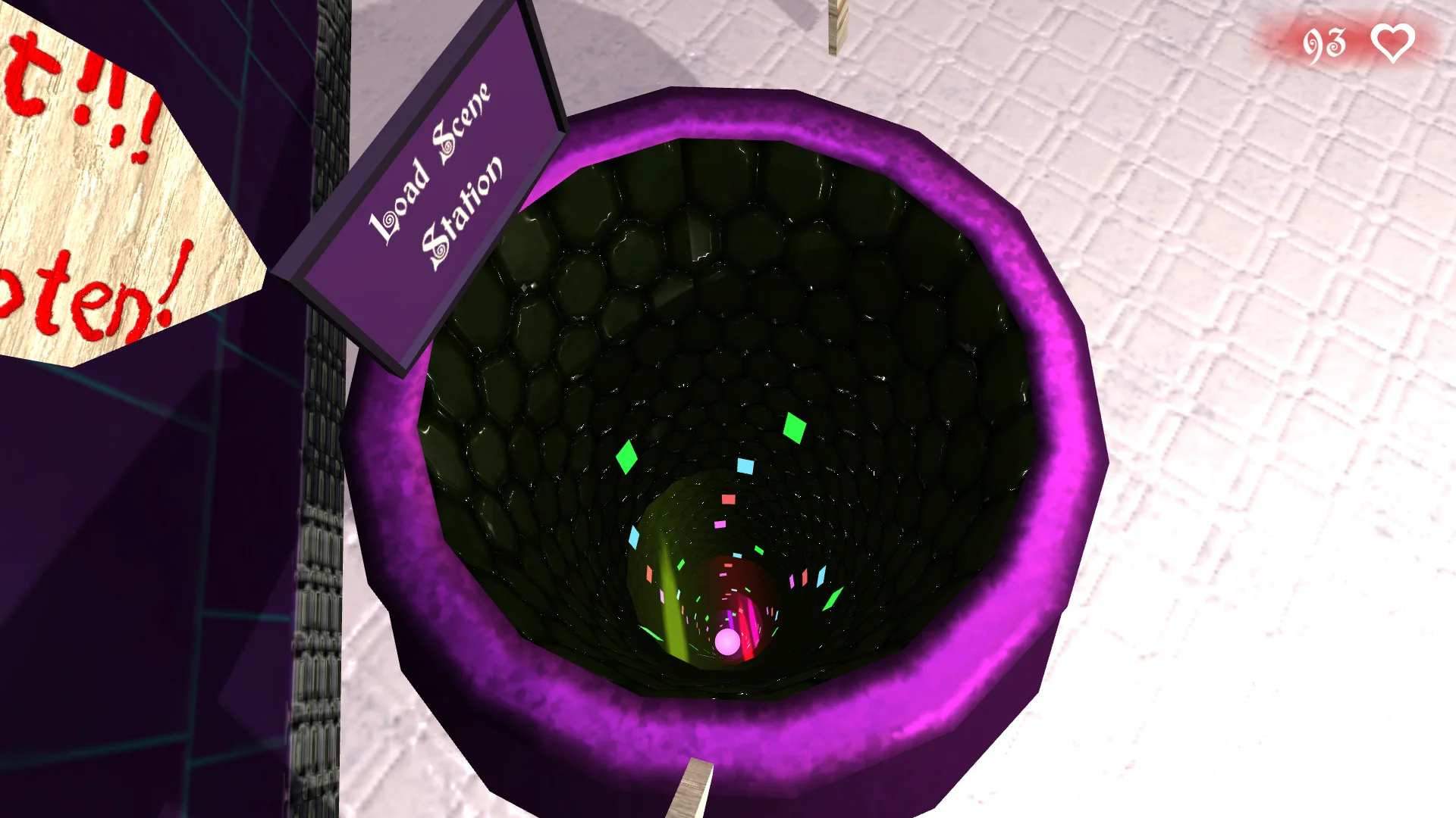

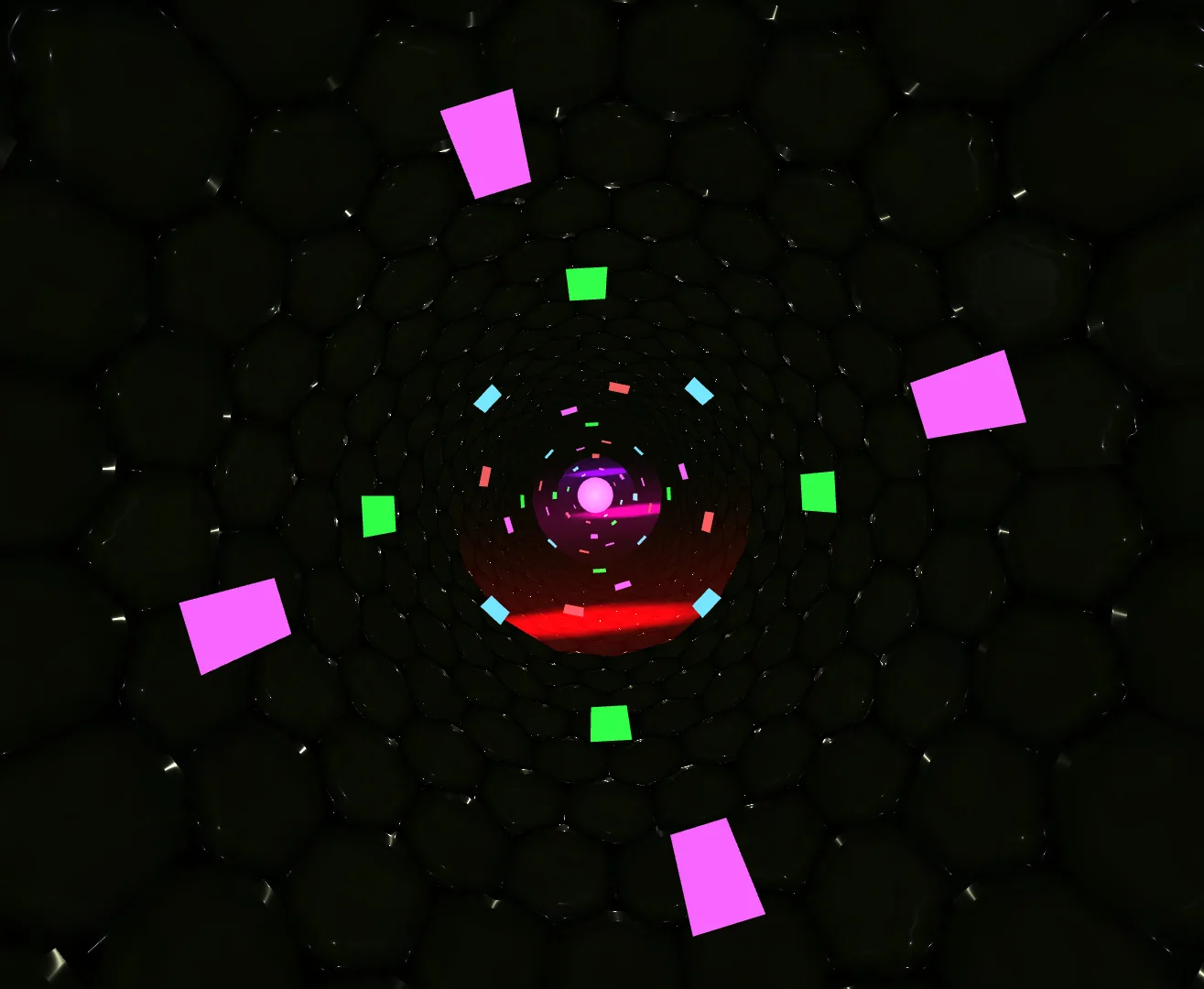


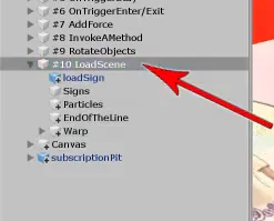

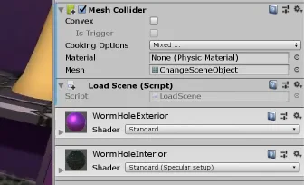

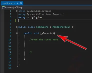

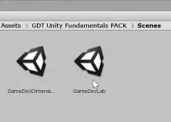

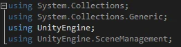

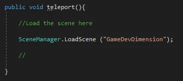

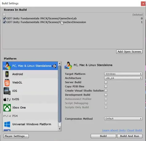


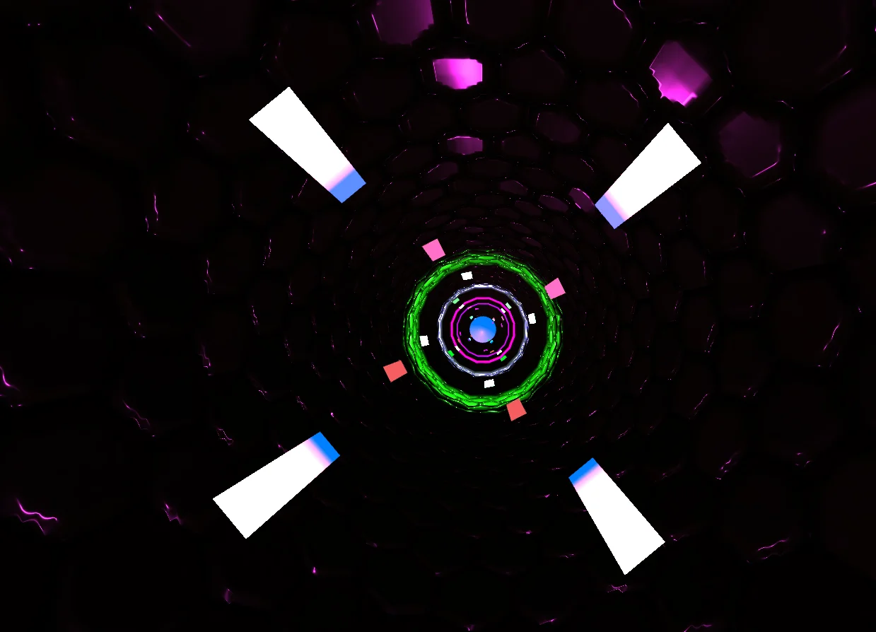

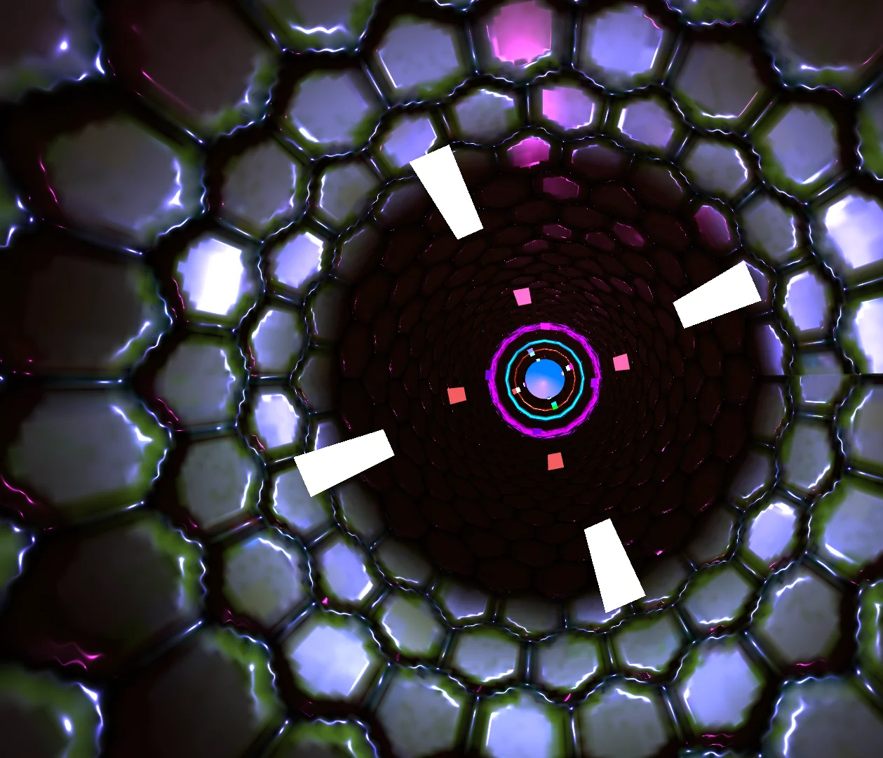

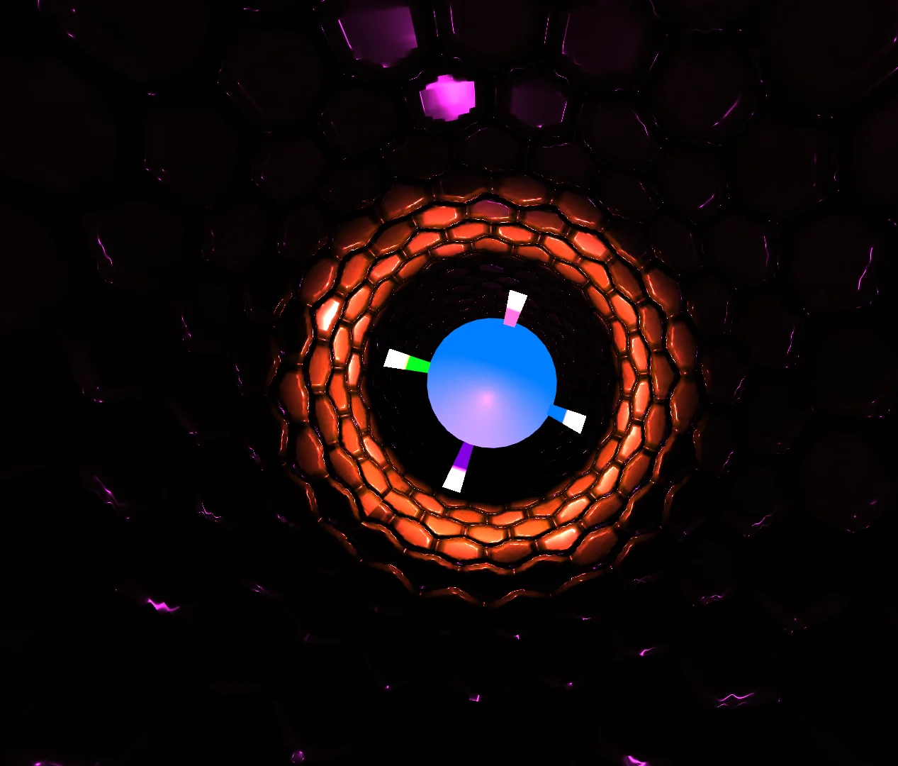

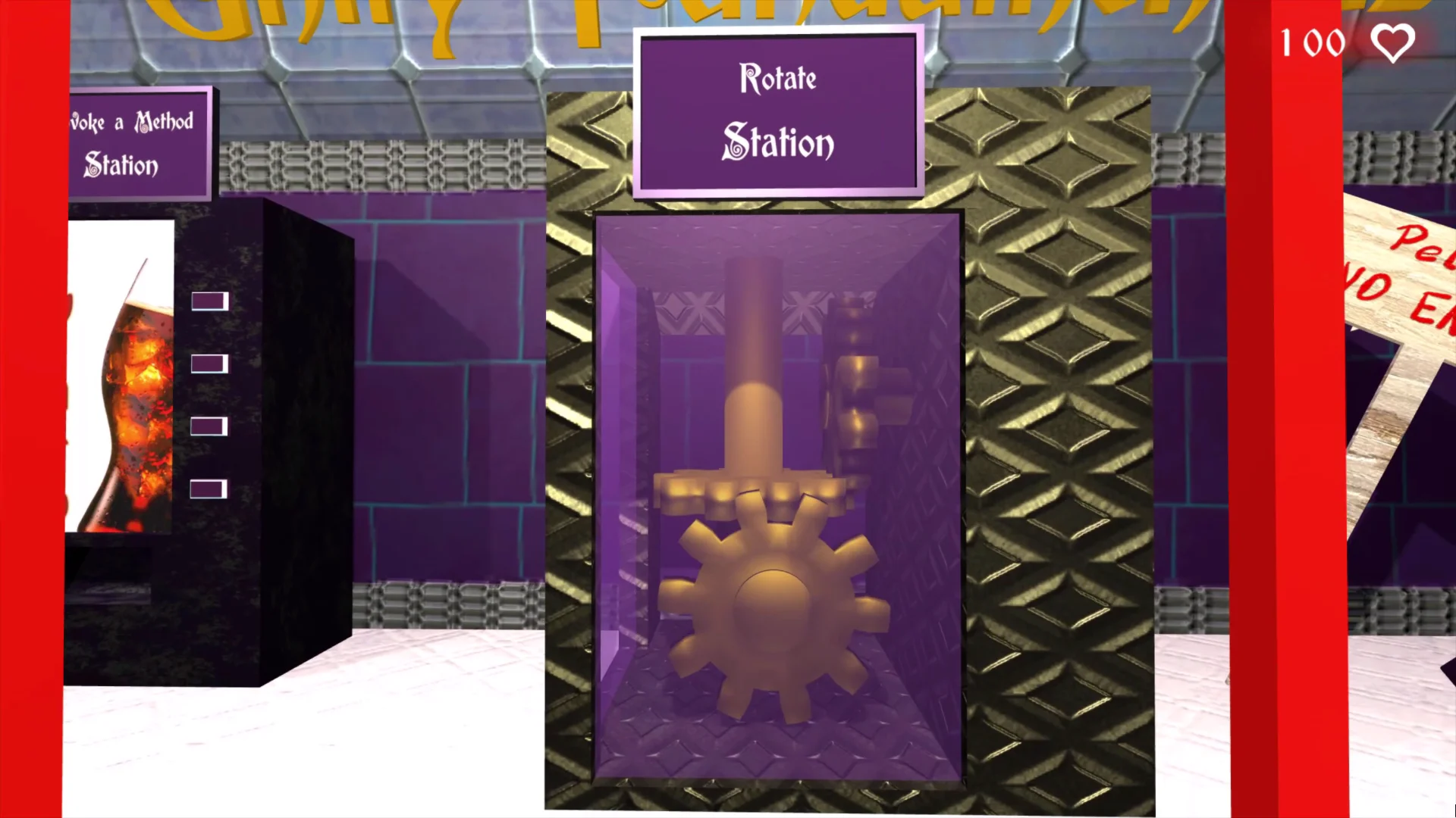
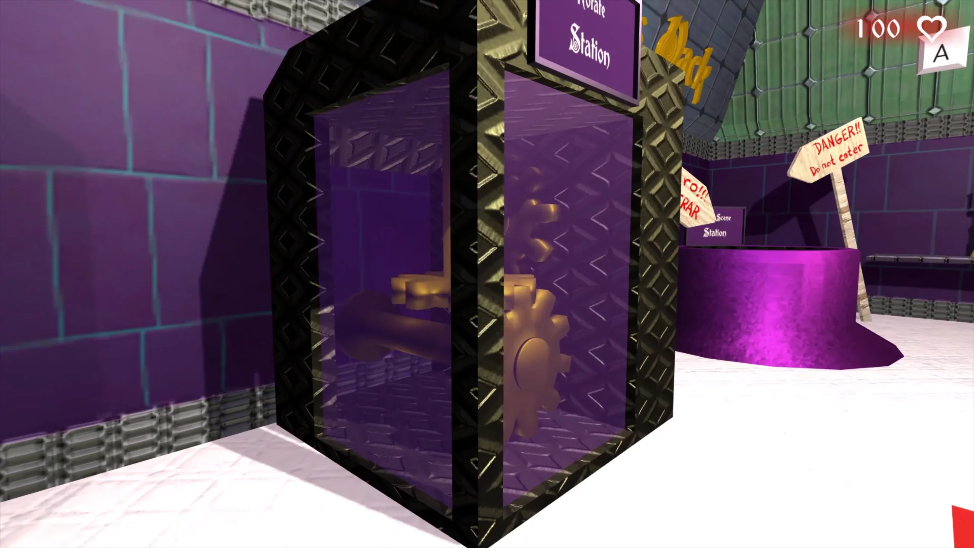

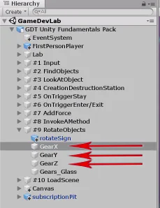

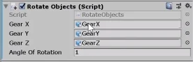

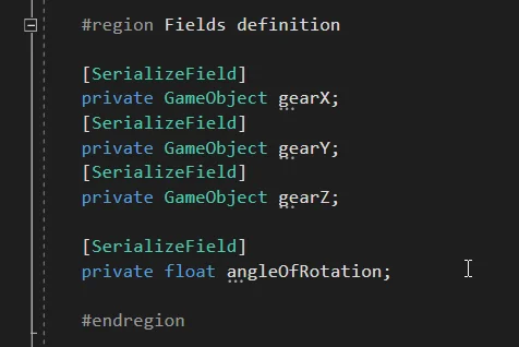

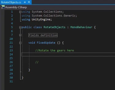

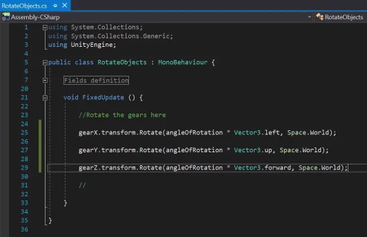

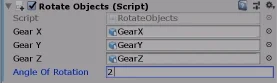

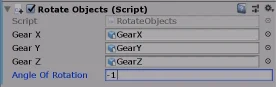


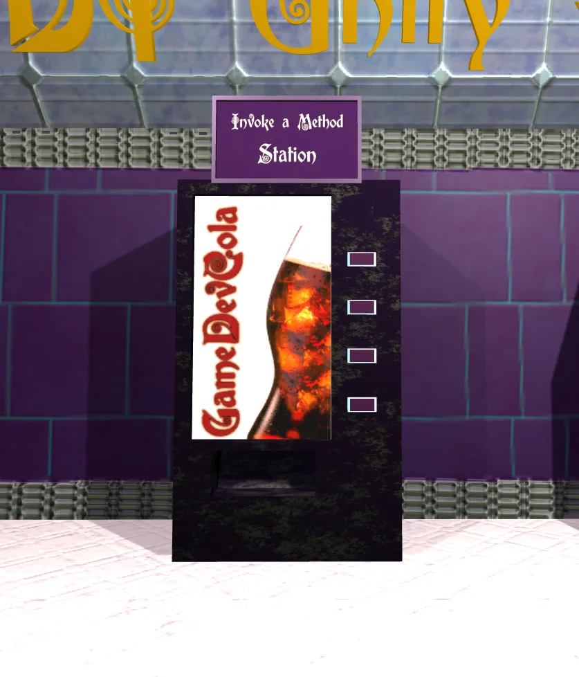


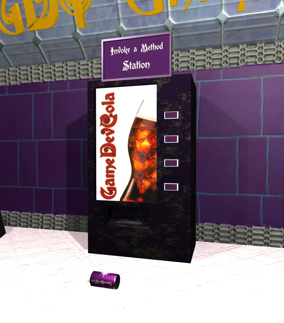

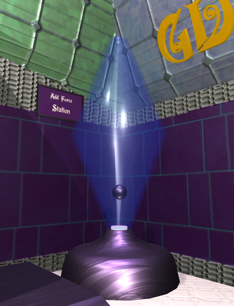


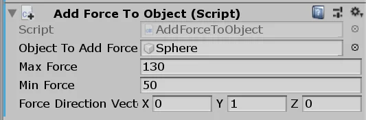

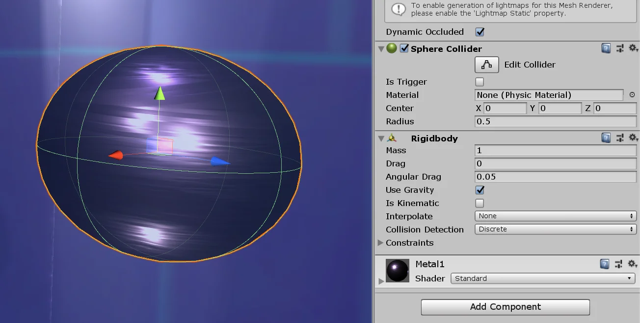

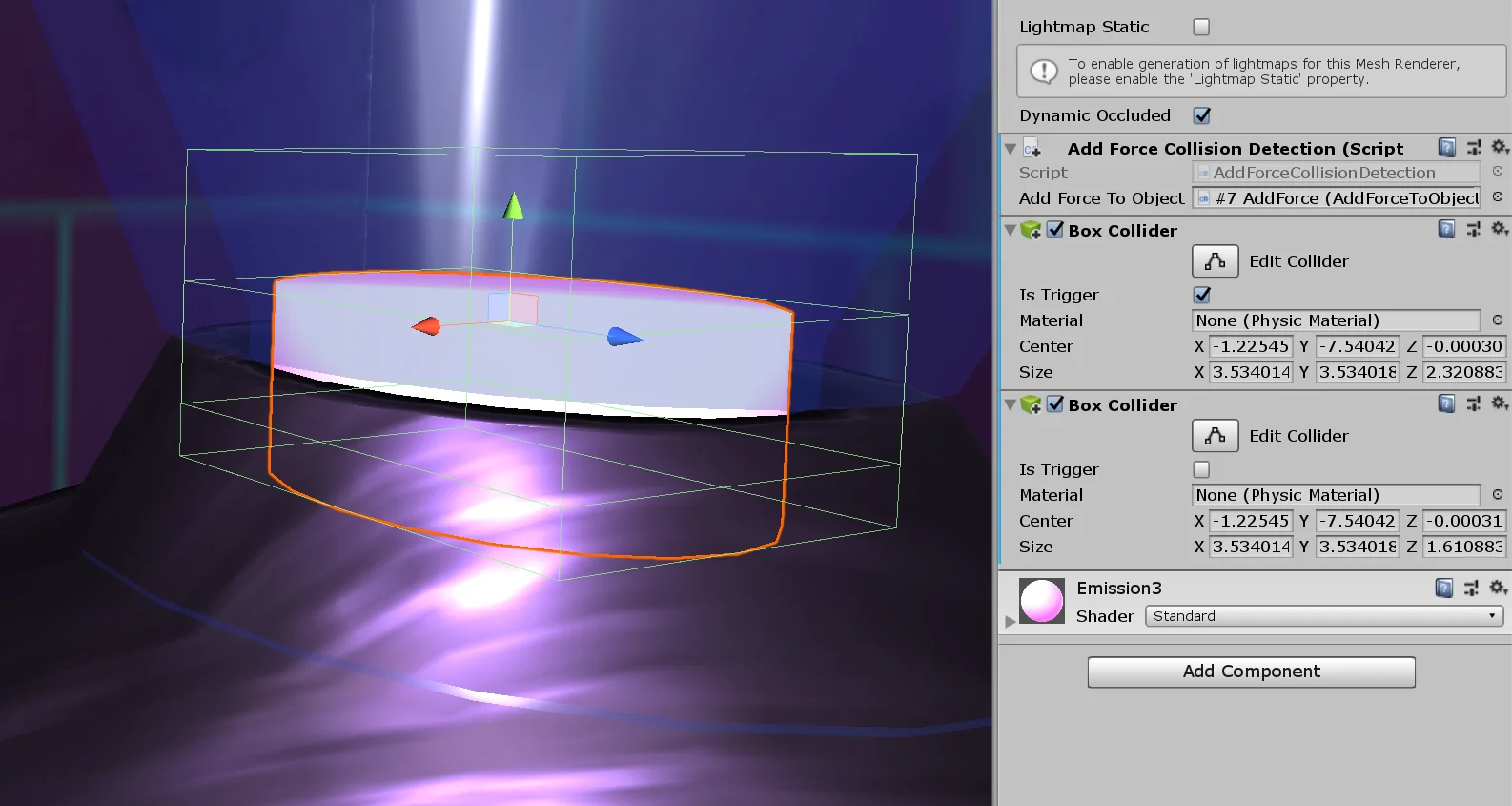


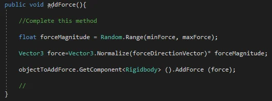

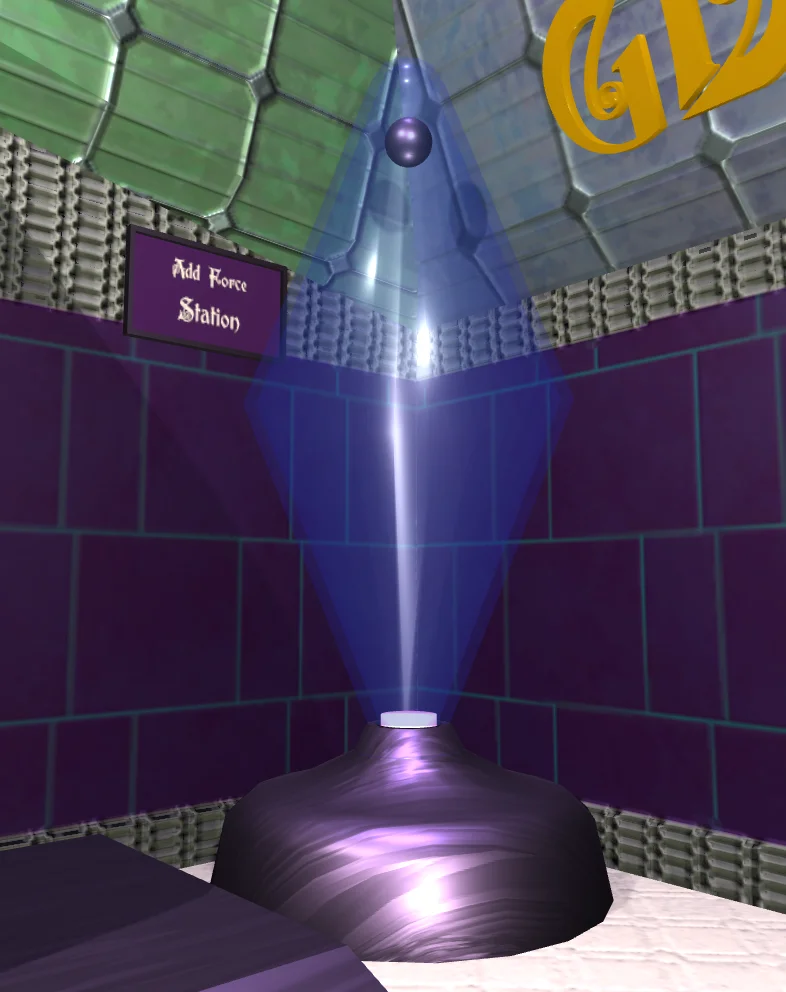


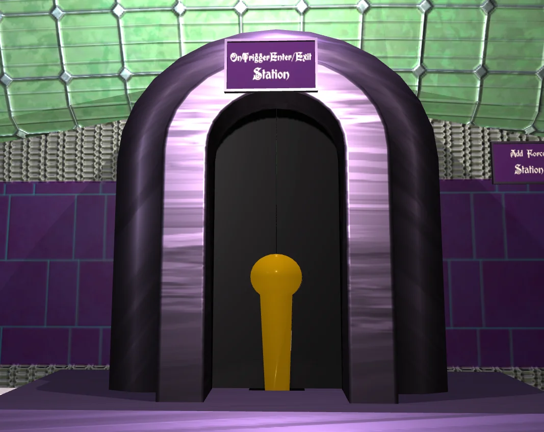

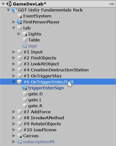

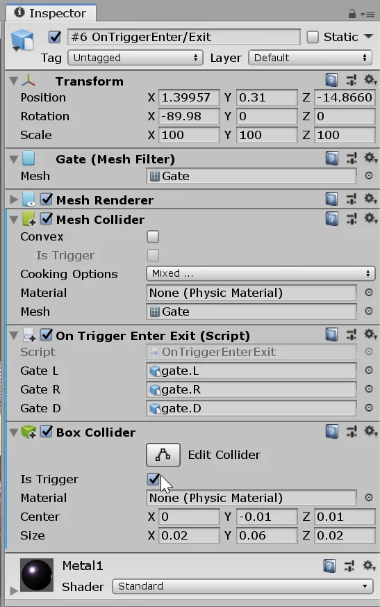

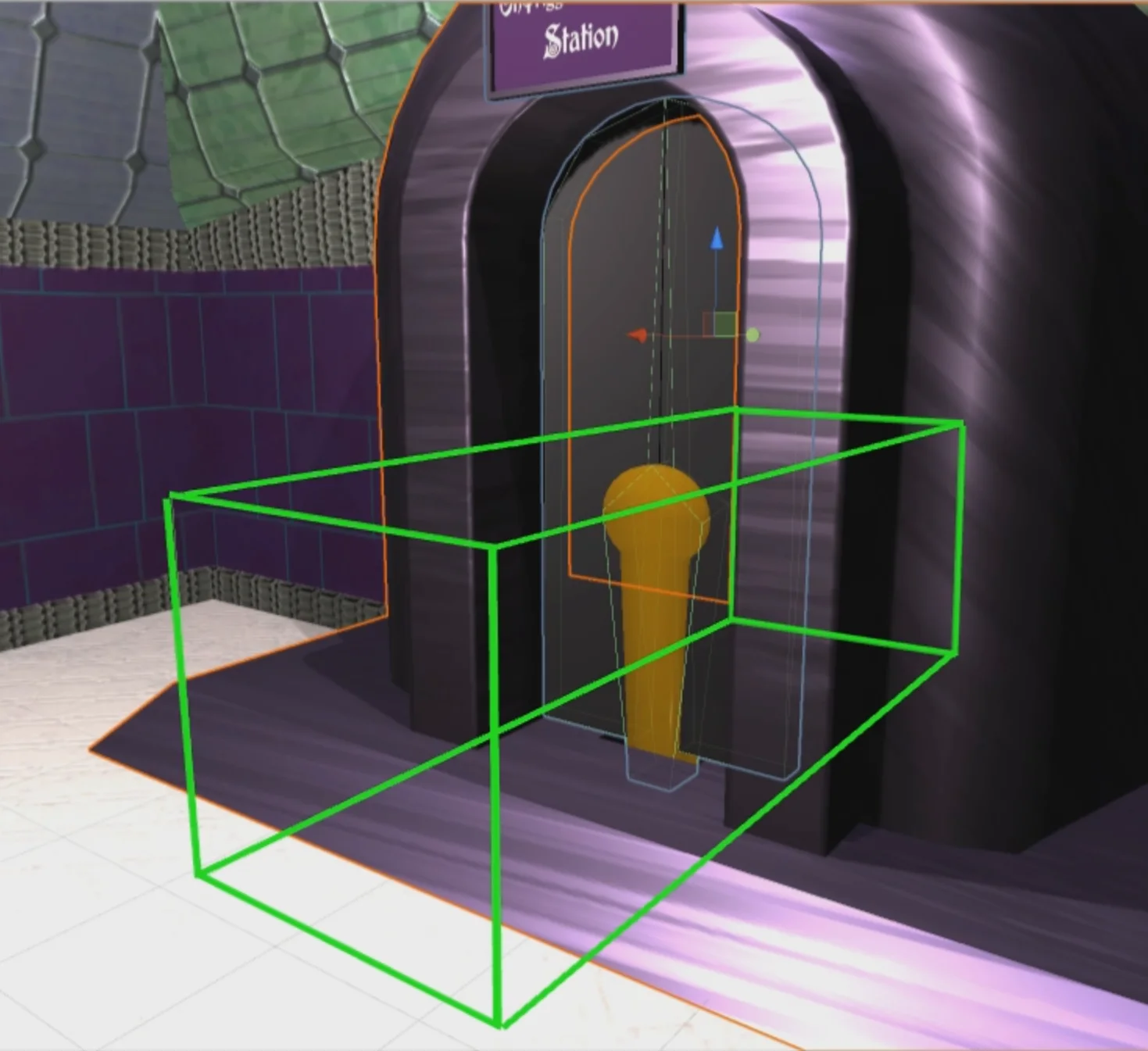

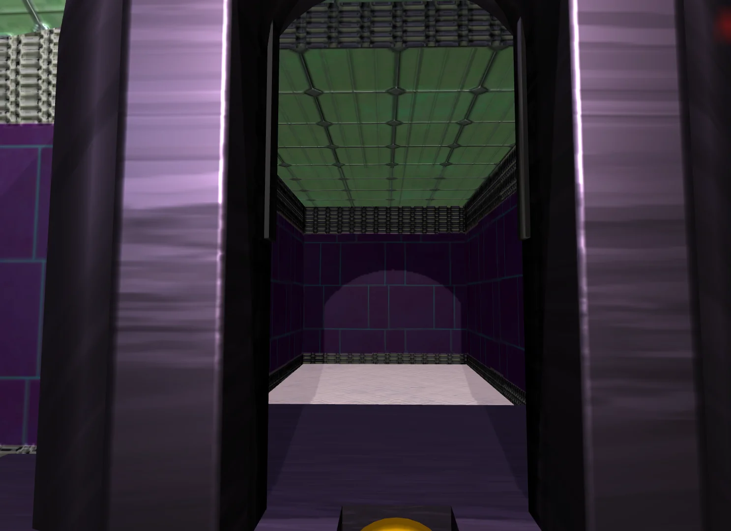

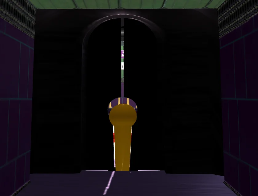


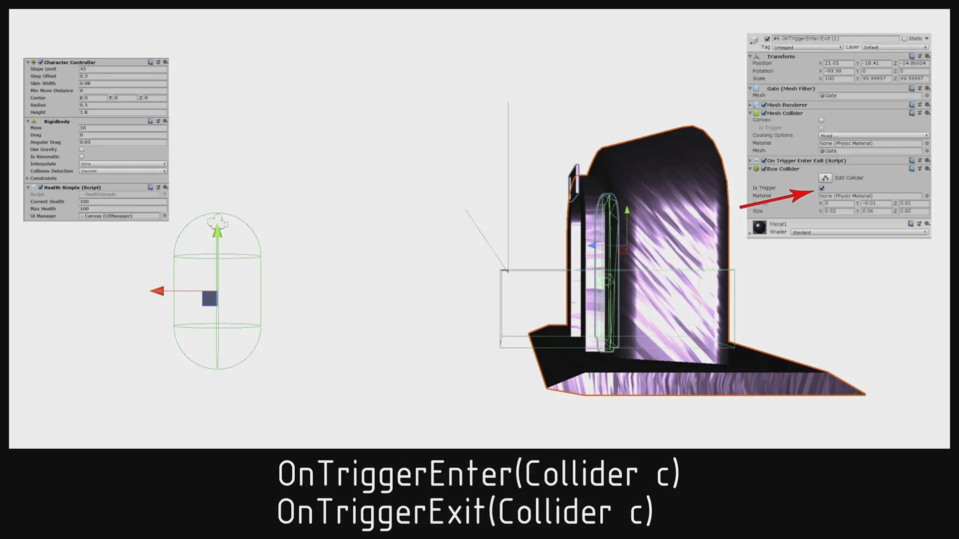
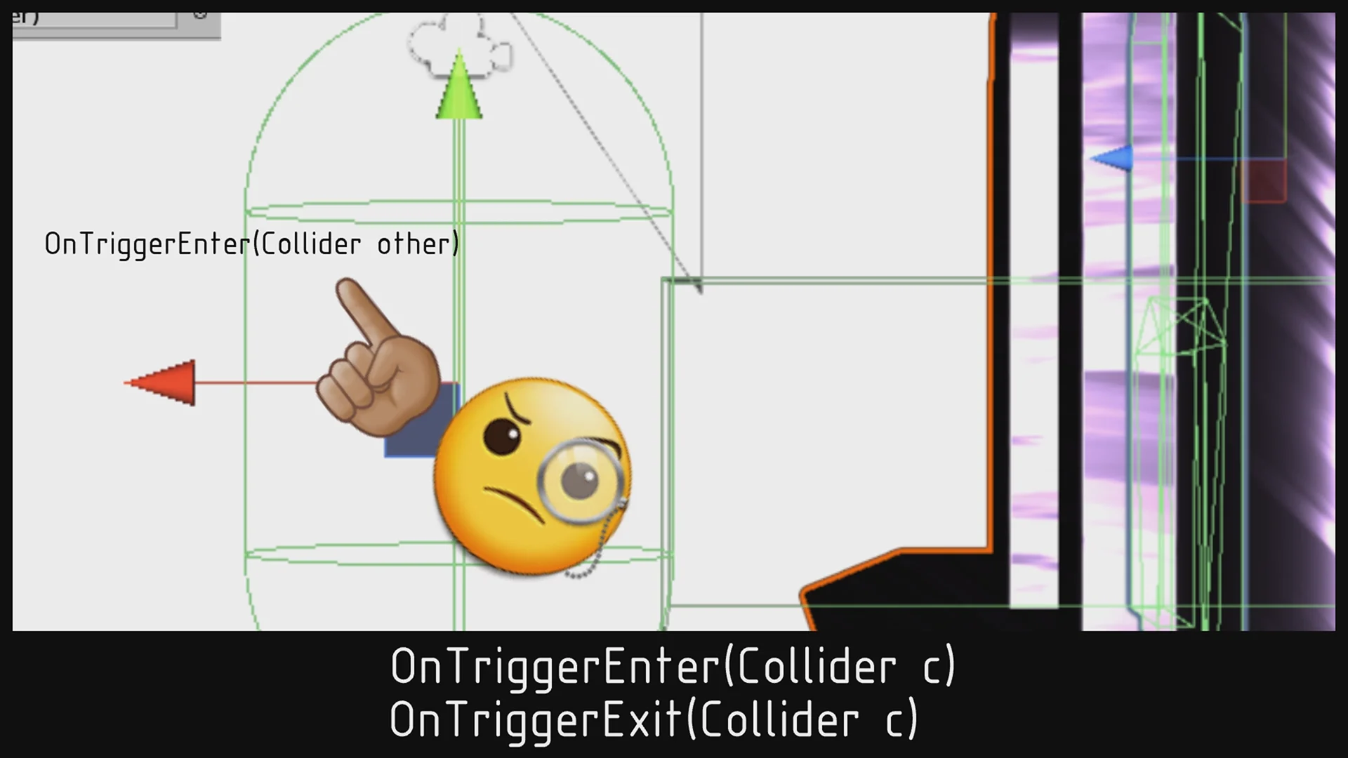


![\[|a| = \left\{\begin{array}{rl} a & \text{si } a \geq 0\\ -a & \text{si } a > 0 \end{array} \right.\]](https://gamedevtraum.com/wp-content/ql-cache/quicklatex.com-f77fd99bf7ed8eadc7db909973c9cd82_l3.png "Rendered by QuickLaTeX.com")