This time I wanted to share a little experiment I did using Blender, Unity and Arduino. The simulation of an industrial process using 3D models made in Blender and making a scene in Unity.
Here in the Alto Valle of Patagonia fruit growing is practiced and as I work doing industrial automation I have the opportunity to observe how the packing sheds work and the treatment of the fruit.
The industrial process I try to simulate is a fruit grinding line. The fruit arrives through a water circuit to a fruit elevator that lifts the fruit to a sorting table, where people manually discard the bad fruit. Then the fruit continues its ascent to a mill where it’s transformed into pulp and deposited in a tank. This is where the simulation comes in.
Motivation
The idea of this experiment combining Unity and Arduino arose because I needed an idea for the final work of a subject of my career. The subject is PLC (programmable logic controllers).
I wanted to take advantage of everything I’ve learned from programming and 3D design, designing a computer simulation to test the programs we load into the PLC.
Description of the experiment
The idea is to use an Arduino Mega board to control the simulation in Unity. This is done using RS-232 communication. The Arduino board is inside a 3D printed box with a pair of Switches on the lid.
With the Arduino Mega you read the status of the switches and with this information you can create a word that is then sent via RS-232. The physical connection is made with the Arduino’s USB port.
In Unity the messages of the COM port are read.
The video shows that there are synchronization problems. This is because the COM port reading is done in the Update method of a class that inherits MonoBehaviour. An alternative to this is to use a different Thread to do the reading.
Conclusion
We haven’t decided yet what we’re going to do for the final work, however, this idea of an Arduino-Unity hybrid project is very interesting to me and I’ll probably make a series of videos for the channel. I think it might be fun.
Introduction
Creating the 3D model of a face can be a challenging task, especially when we’re just getting started in the 3D world. In this article we will see an easy and practical way to make a 3D face with a well-achieved geometry in Blender, but the technique can be applied in any 3d design software.
Timelapse of the modeling process of a 3D face
In the following video I use this process to make the 3D model of a Venetian mask. The textures were made using Substance Painter.
Topology is the discipline that studies objects and their geometric properties. In 3D models it refers to the set of vertices, edges and faces and their interrelation.
It’s very important that our 3D models have a good topology, that way the modifiers, proportional deformation, texture painting and other functions will have better results.
We achieve this by using 4 vertex faces (quads) and creating edge loops that fit the natural curves of the object we want to model. In the figure 1 we see those faces and how they are distributed in the 3d model.
Fig. 1: Reference image for 3d face topology. Source:Blender Artist.
If we use this kind of images as reference for our modeling procces we will achieve a 3D model of a face with a correct topology.
Reuse of the 3D model for a character
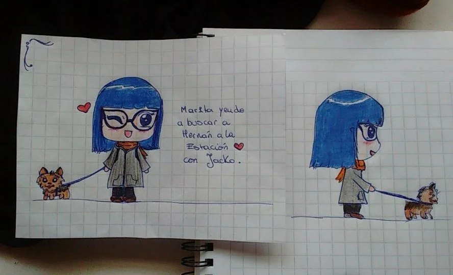
Marittie is a chibi character I made from a drawing my girlfriend made some time ago.
Fig. 2: Reference image for the Marittie 3D model.
At the time, I had a year’s experience with Blender and was not yet familiar with the concept of topology. However, I managed to make a model and at that time I liked it very much.
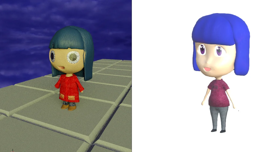
Fig. 3: Render of Marittie’s old model.
The topology of course was not good. The model had a very high number of polygons, triangles, quads and n-gons, very badly optimized.
The animation was of course difficult to achieve. There were irregularities that were difficult to correct.
Fig. 4: Another render of the old model.
As time went by I learned to improve the geometry and it was time to remake the 3D model.
I had made the 3D model of the Venetian mask, so I thought why not use this 3D model as a starting point for my character design?
I made a copy of the mask and started applying proportional deformations. As the topology of the face was good, it was easy to transform the Venetian mask into Marittie’s new face.
Fig. 5: Render of the new model.
Fig. 6: Another render of the new model.
Fig. 7: Comparison of the old model and the new model.
Conclusion
It is important to achieve a good topology in our 3D models, because that means we can apply transformations to that mesh and it will respond appropriately.
The improved topology of the new model makes animation easier. The proportional deformation tool has better results and also the seam marking and UV unwrapping will be easier.
I wanted to share a project I did long before I started programming and the world of video games. It’s a computer cabinet made in mdf.
History
I had been making things in mdf, such as sets of chess and boxes that my girlfriend had decorated with decoupage, I liked quite and had ease. One day I was in chemistry class in the university and I showed a friend the little jobs I had done. He was interested and told me that he needed a temporary wooden box to cover his computer because he had not yet got a cabinet and his computer covered it with a cardboard box.
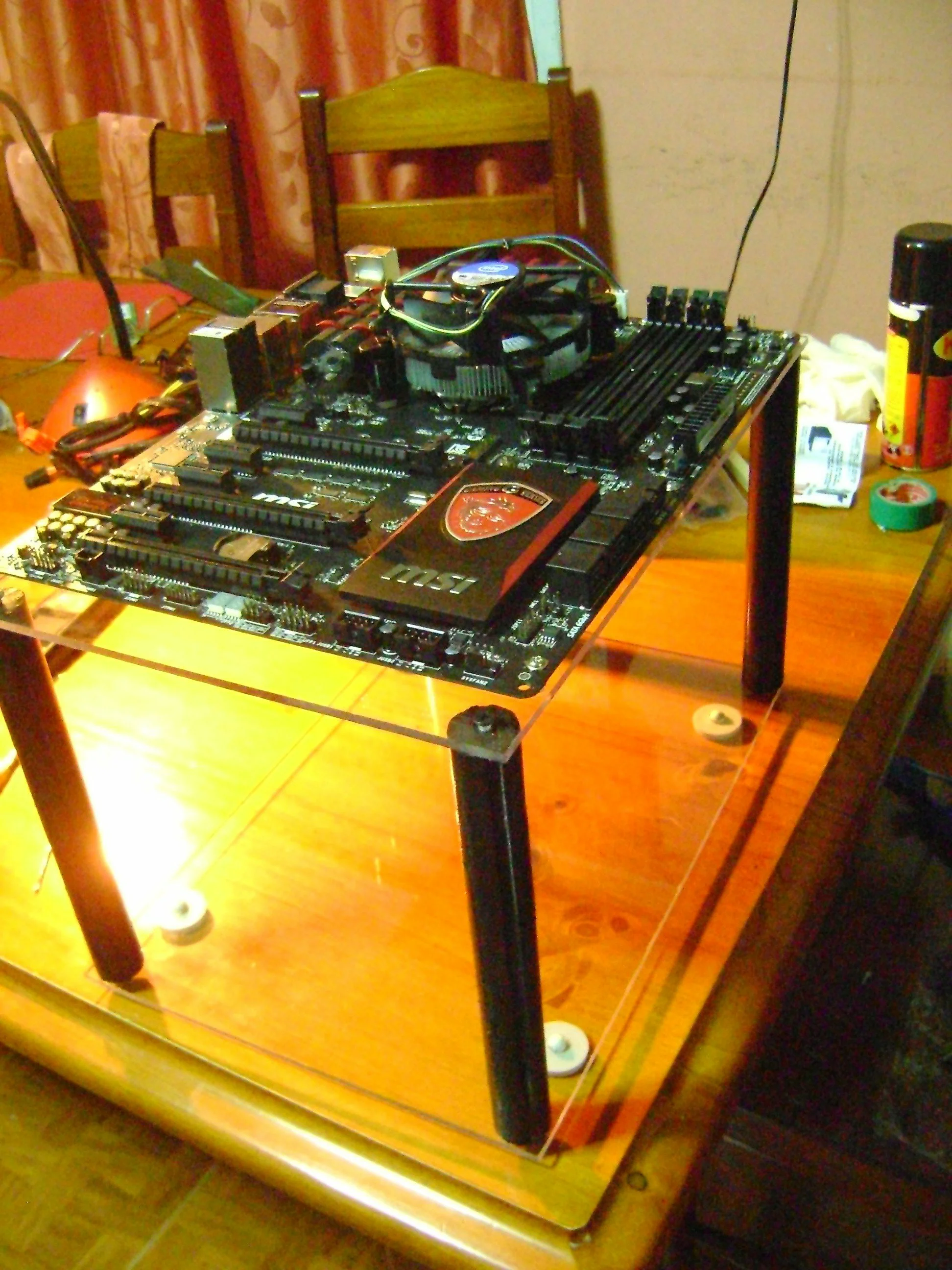
Figure 1 shows a structure for the motherboard and power supply that he made.
Fig 1: Supporting structure.
Fig 2: Initial disposition of the elements. Below power supply and hard disk.
So the idea was to make a box containing that to prevent it from getting dusty.
Design of the MDF PC case
My friend made a design that seemed convenient for ventilation and from that I made a 3D design using SolidWorks (at that time I didn’t know Blender), that was my first approach with 3D modeling without counting that when I was a kid I made maps for Counter Strike using 3D Entity.
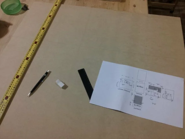
With the 3D design we were able to make some renders and adjust it until it became as my friend wanted. From that 3D design I made a plan of 6 views for the cuts of the pieces (I believe that by that time I had also made technical drawing in the university).
Fig 3: Part of mdf and plane of the cuts.
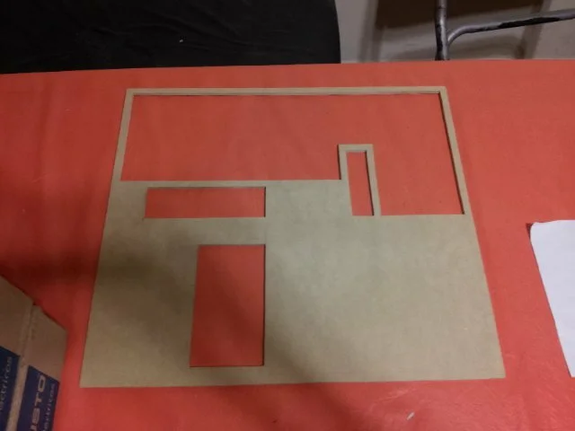
Taking as base the plans, I drew the six pieces on a plate of mdf of 5 mm of thickness, in this part the measures were taken well so that everything is to square.
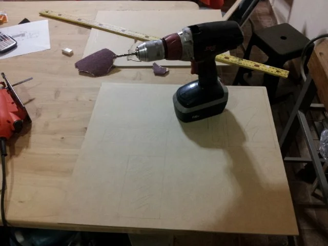
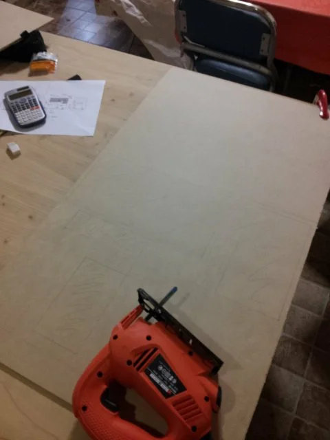
Fig 4: With all the cuts drawn, holes are made so that the sheet of the jigsaw can enter.
I made all the holes in the internal cuts so that the sheet of the jigsaw enters.
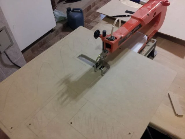
Fig 5: Cut from one side.
I made the simple cuts using a hand jigsaw and the precise cuts with a bench jigsaw.
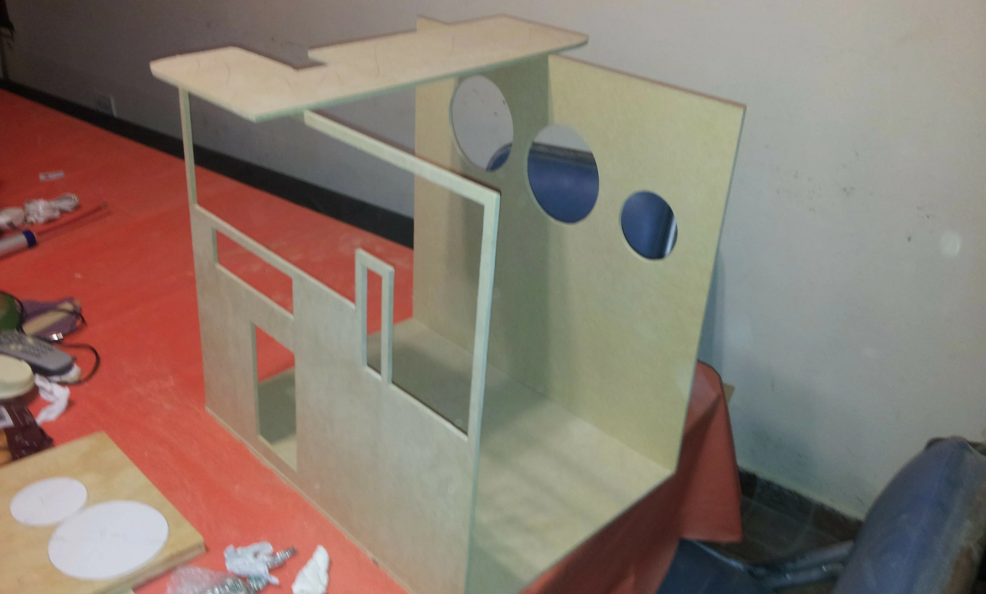
Fig 6: Inside cut of a side piece of the mdf cabinet.
The cuts were made to measure, only not so straight because they were made by hand.
Fig 7: The first piece of the mdf cabinet, one of the sides.
Figure 8 shows that the structure was already taking shape.
Fig 8: Cabinet parts cut without gluing.
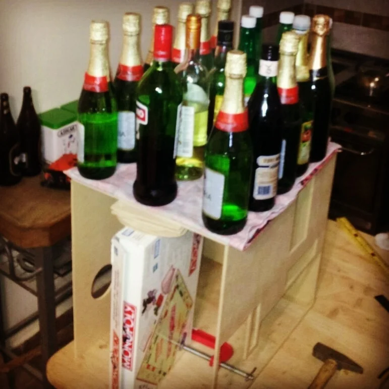
I glued the three pieces using glue and then applied a press so that the structure is very firm, then the pressing tools are observed.
Fig 9: Gluing and pressing of the mdf cabinet.
Notice how the red metal press (a press itself) is in charge of keeping Monopoly’s box armed, so the structure didn’t collapse under its own weight.
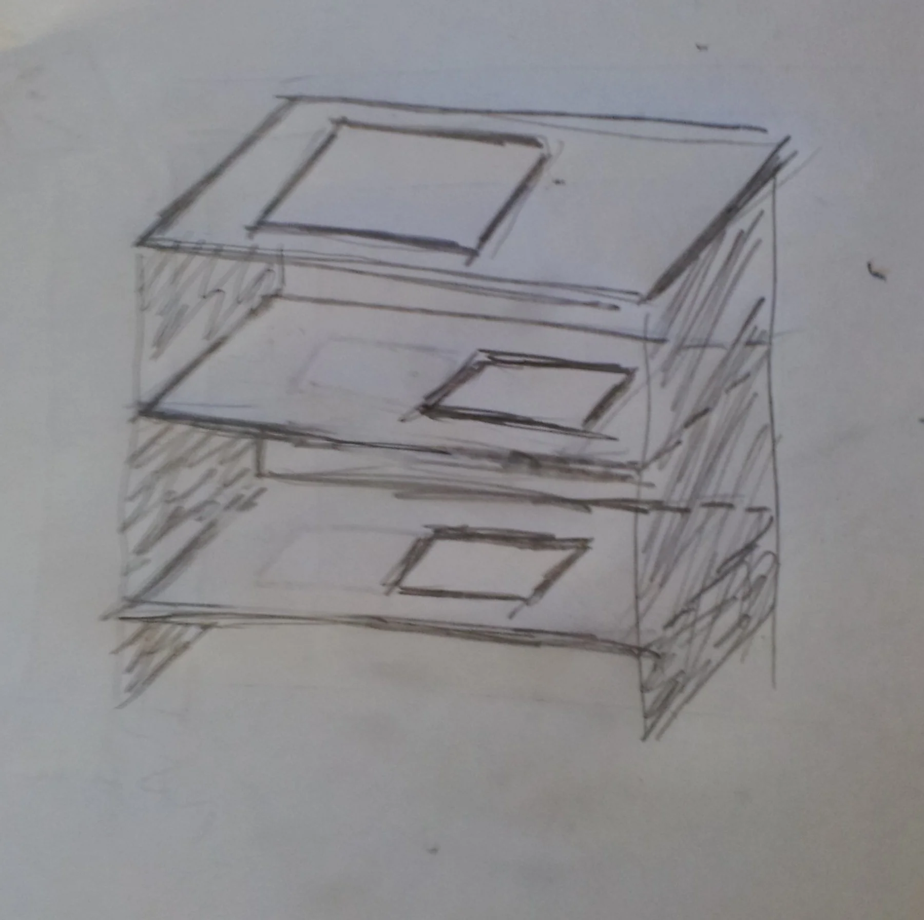
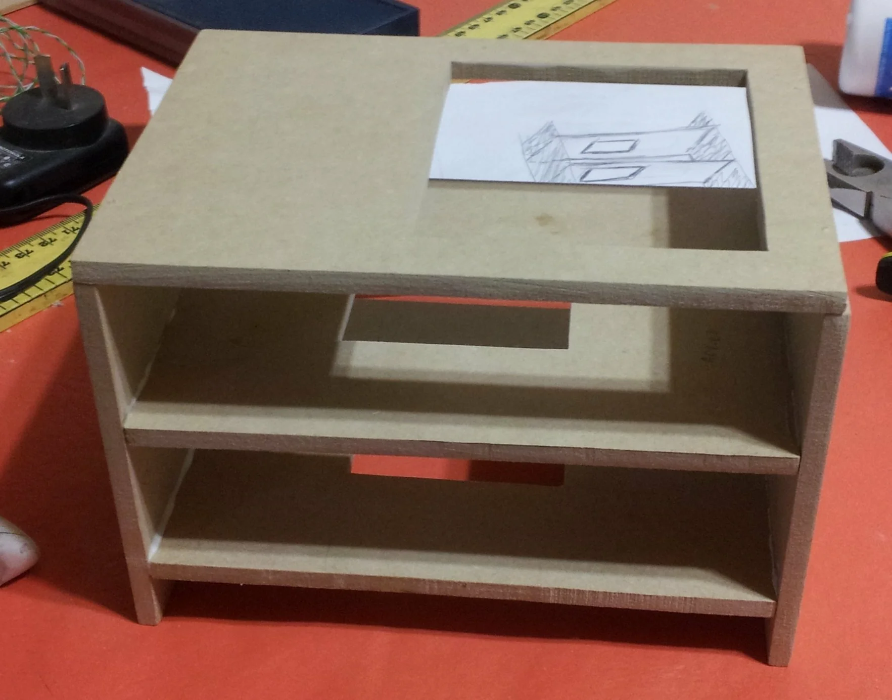
Fig 10: Design for disk bays.
For the disk bays we made a three-storey structure, in the following figure the idea for the design is shown.
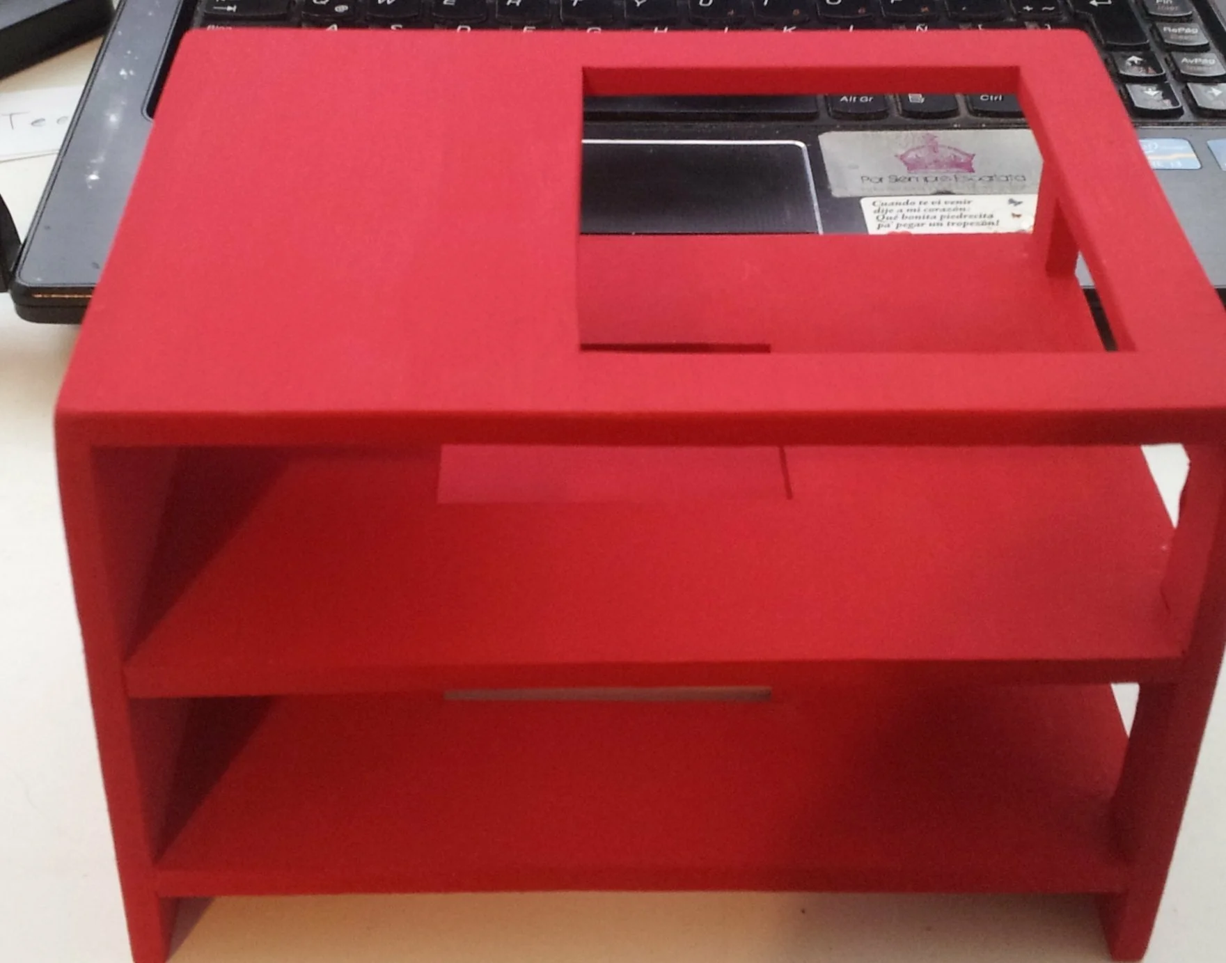
Fig 11: Unpainted disc bays.
The piece was also built with 5 mm mdf and a layer of red acrylic paint.
Fig 12: Disc bays finished.
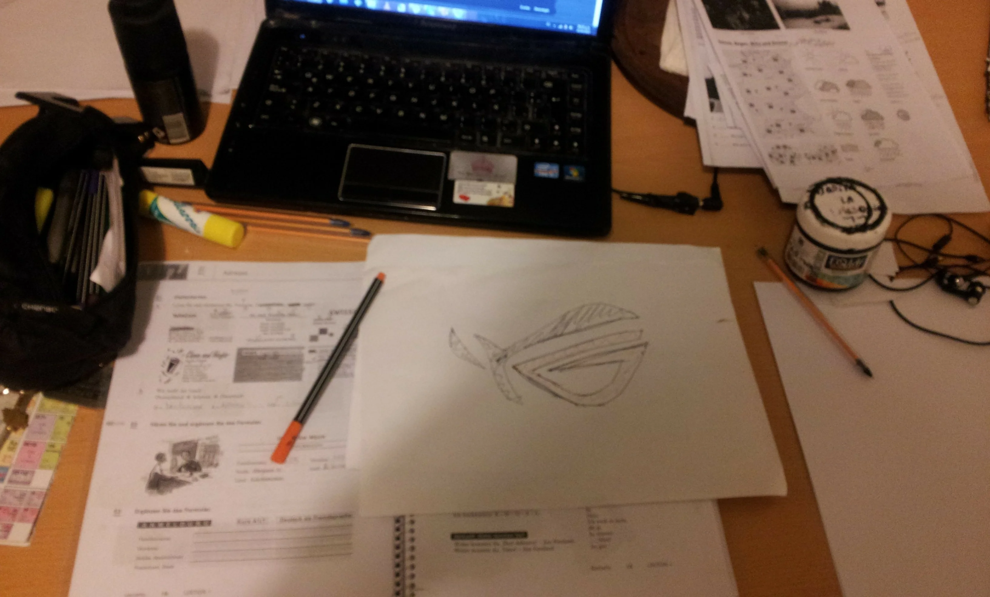
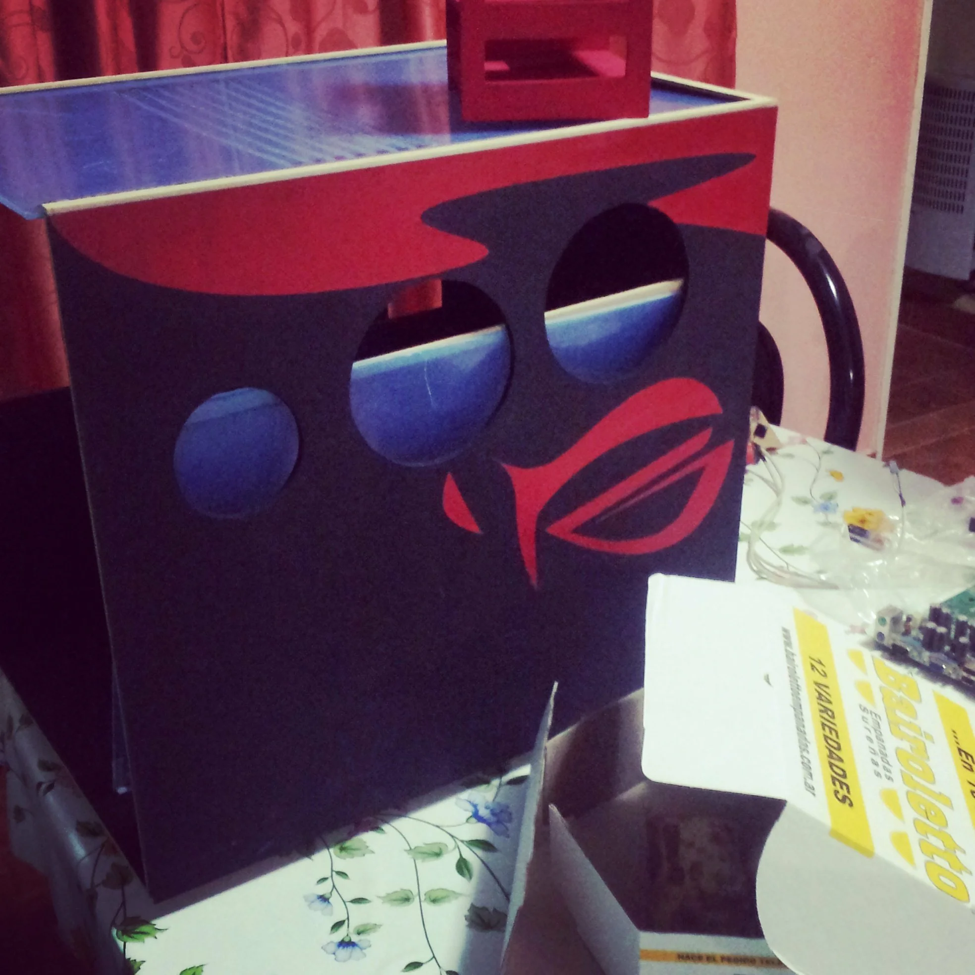
Then we started to think about the decoration of the box, because it had to have even a coat of paint. At that time I didn’t know as much about computer components and brands as I do now, however I proposed some designs that he liked.
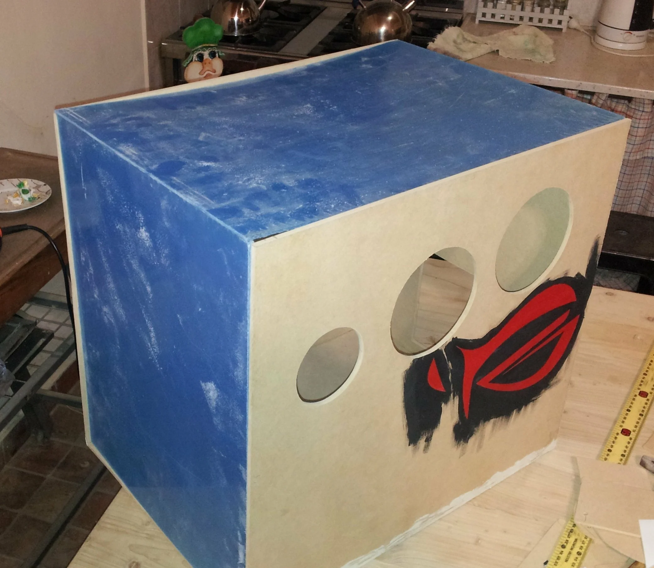
Fig 13: Scribbling some designs while doing my German homework.Fig 14: The mdf cabinet after gluing and with part of the design. The blue pieces are transparent acrylic.
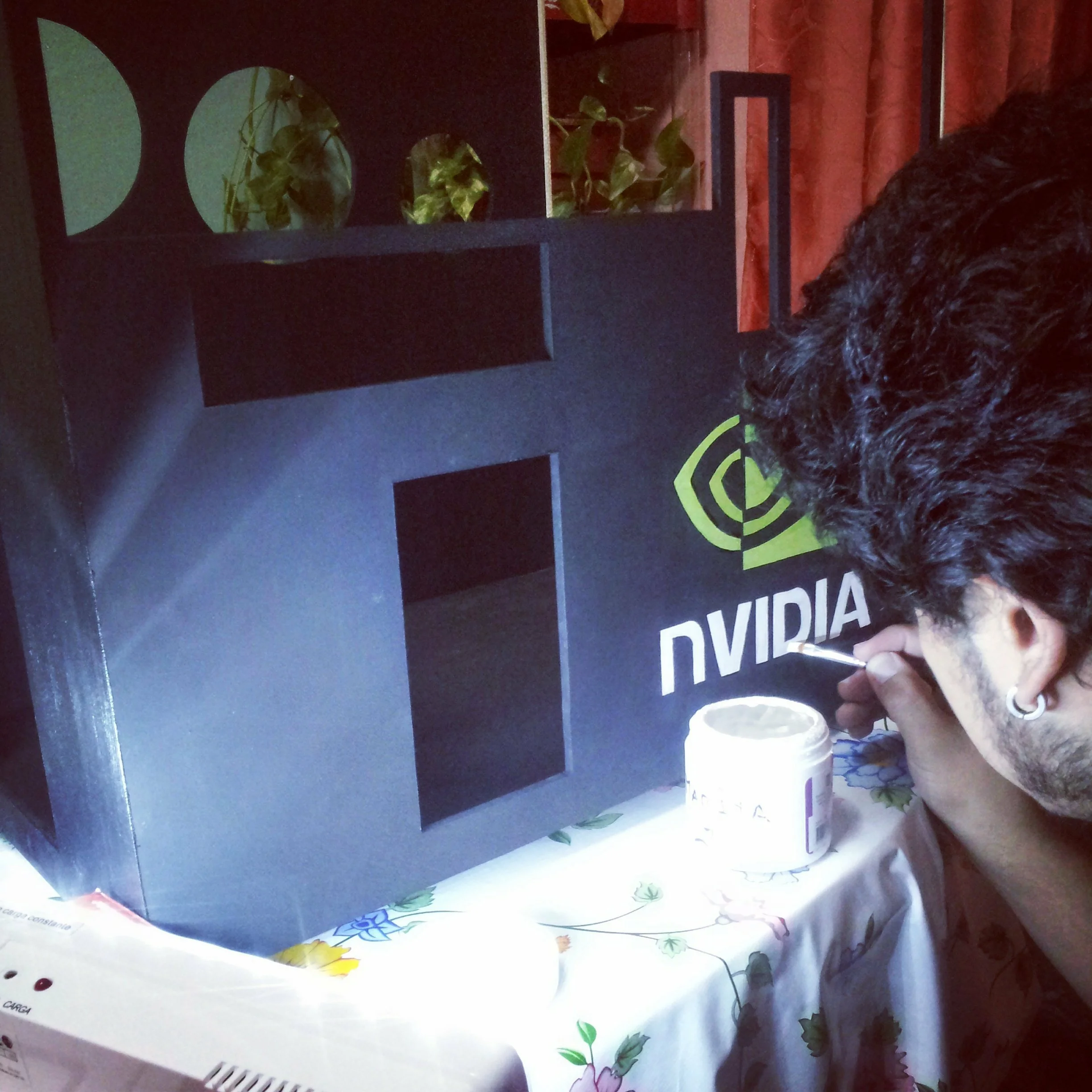
The Republic of Gamers logo for an MSI board, I know.
Fig 15: Side of mdf cabinet, notice the acrylic placed in a groove at the top.
We had bought some meat pies to eat and it was getting late.
Here you can see that I’m putting the finishing touches. Our mdf cabinet was almost finished.
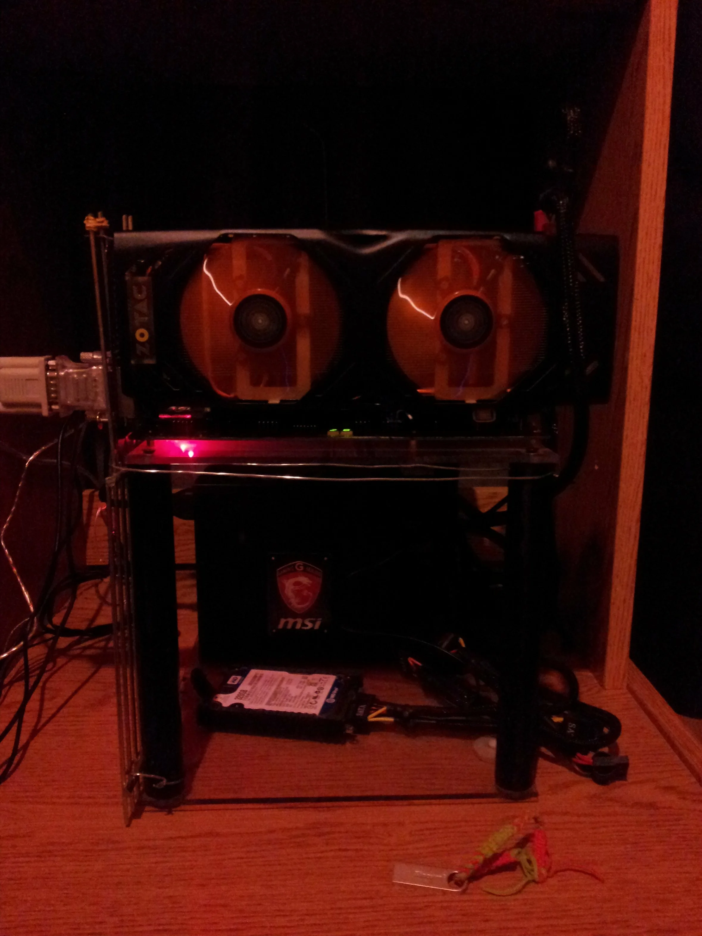
Fig 16: Retouches in the decoration of the cabinet mdf.Fig 17: Cabinet mdf with screwed coolers.
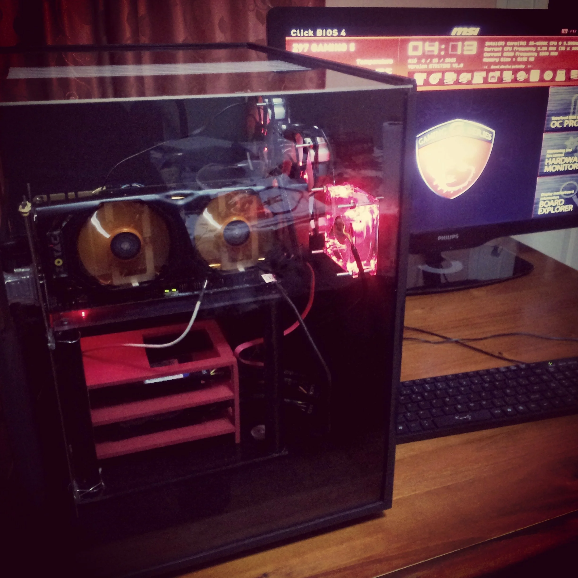
We screwed the coolers in place, placed the structure with the motherboard, the fountain, the disks inside and finally the two pieces of acrylic that went into grooves. This was the final result
Fig 18: Final finish of mdf cabinet.
Conclusion
We managed to finish the mdf cabinet and my friend had a small box to house his computer. It was temporary until he finally got a PC cabinet.
In my opinion the dimensions were quite exaggerated, but my friend was worried (and rightly so) about refrigeration. In a metal cabinet the heat is partly dissipated by the thermal conductivity. In addition it provides protection to the circuits against electromagnetic noise.
However, if we take into account the fact that I used to cover the computer with a cardboard box, the mdf cabinet was a small improvement.
This website uses cookies to improve your experience. We'll assume you're ok with this, but you can opt-out if you wish. Cookie settingsACCEPT
Privacy & Cookies Policy
Privacy Overview
This website uses cookies to improve your experience while you navigate through the website. Out of these cookies, the cookies that are categorized as necessary are stored on your browser as they are as essential for the working of basic functionalities of the website. We also use third-party cookies that help us analyze and understand how you use this website. These cookies will be stored in your browser only with your consent. You also have the option to opt-out of these cookies. But opting out of some of these cookies may have an effect on your browsing experience.
Necessary cookies are absolutely essential for the website to function properly. This category only includes cookies that ensures basic functionalities and security features of the website. These cookies do not store any personal information.


![[3D PRINTING] Box for the ARDUINO MEGA](https://i.ytimg.com/vi/Fq2yaB1s-E8/hqdefault.jpg)