In this article we are going to study the geometric figure circle, its characteristics and mathematical equation.
Definition of a circle
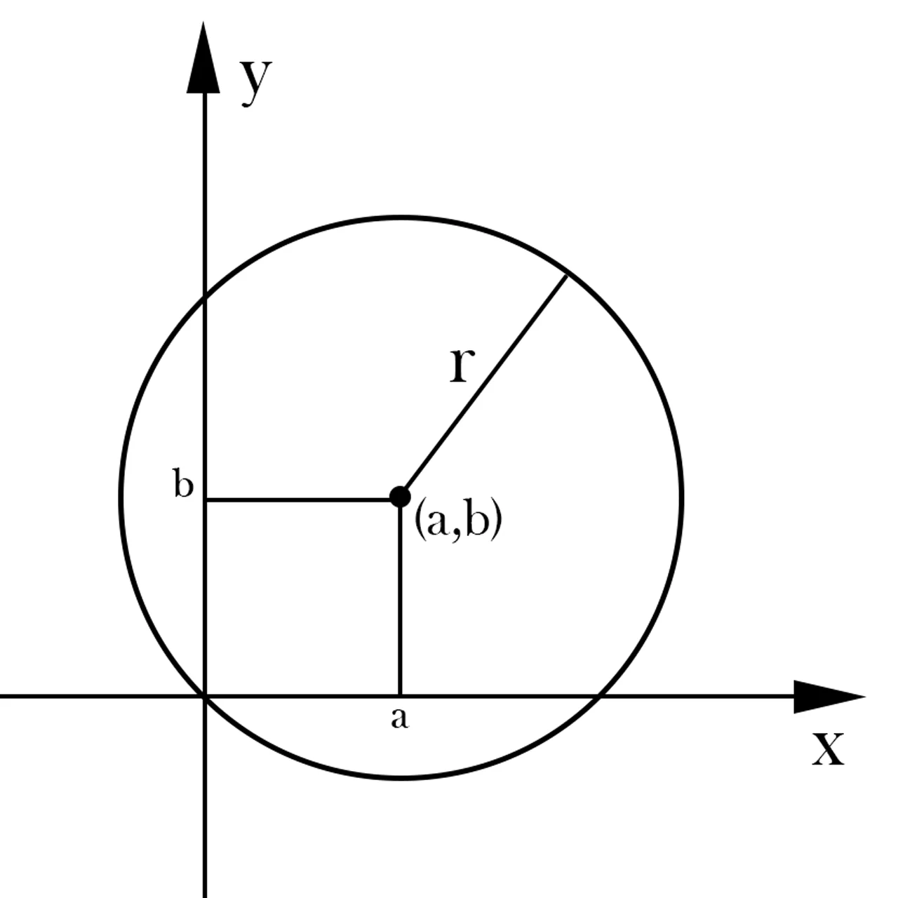
A circle is a geometric figure in which all its points are at the same distance from a given point called the center, this distance is known as the radius of the circle.
Fig. 1: Graph of a generic circumference of radius R and centre at point (a,b).
Equation of a Circle
Knowing the mathematical expression of a circumference we will be able to draw it in the Cartesian plane and later use it in our projects of programming and development of videogames.
Cartesian coordinates
The expression that defines a circle in Cartesian coordinates is the following:
(1)
Where R is the radius of the circumference and its center is located at point (a,b) of the Cartesian plane.
In this case to draw the circle we must know the range of values of the variables X and Y. For example, let’s consider the circle unit centered in (0,0):
(2)
If we draw a circle of radius 1 with center in (0,0) we can see that both the values of X and Y will be in the interval [-1,1]. By choosing a value from that interval and assigning it to one of the variables we will be able to clear the equation and obtain the value of the other variable.
Parametric coordinates
The expression of a circumference in the parametric coordinate system may also be useful, since the range of variation of the parameter is infinite since it is defined with periodic functions. The expression of a circle is given by the following system of equations.
x=a+r.cos(t)
y=b+r.sin(t)
(3)
By varying the t parameter between 0 and 2π we obtain all the points of the circumference.
As we mentioned before the parameter t can take values from less infinite to more infinite and will always return some point of the circumference, because the sinuses and cosines are periodic functions.
Circle and mathematical functions
It must be borne in mind that there is no mathematical function that defines the circle since, by definition, a function is an expression in which it is fulfilled that, for each value of the independent variable, there is only one value for the dependent variable.
In others for it to be a function we must be able to draw a vertical line anywhere on the graph and this should cut the function into a single point. This does not happen in the circle, since if we take for example the line coincident with the Y axis, we see that it cuts the circle unit centered in (0,0) in two points.
What we can do is clear the variable and in equation 1.
(4)
The absolute value arises when taking the square root of an expression that is elevated to the square, this gives rise to two possible values for that expression, one positive and the other negative, that define the lower and upper cap of the circumference.
Semicircle – Concave from below
The expression of the function that represents the top semicircle of a generic circle is:
(5)
Semicircle – Concave from above
The expression of the function that represents the bottom semicircle of a generic circle is:
(6)
Perimeter of a circle
The perimeter of a circle is the length of its boundary, let’s imagine that we make a mark in a point of the circle, we place that point in the 0 of a line and we make it turn forward, the point where the mark touches the line again is the value of the perimeter of the circumference. Mathematically it can be calculated as:
(7)
Pi has an approximate value of 3.1415 and r is the radius of the circumference.
Area of a circle
The area of a circle is the result of multiplying the number Pi by the radius of the circle squared. Mathematically:
(8)
Introduction
In this article we are going to see how to export 3D models, with materials, UV maps and animations, from Blender to the Unity engine, in which format and a some useful tips to prepare models before exporting.
The process is simple, being in object mode, we select the 3D model or models that we want to export. Then click on File > Export and choose the format to which you want to export it.
In my case I always check the “Selected Only” box to export only the selected 3D models to Unity.
Format to use
The format I use is .fbx (Filmbox), which has not given me any inconvenience and allows me to export the materials contained in the 3D model, the animation skeletons, the actions defined with the Action Editor and the Shape Keys.
Things I take into account before exporting
Before exporting from Blender to Unity I try to improve certain aspects of the 3D model in order to have everything as organized and simple as possible.
About the names of the 3D models
In Blender’s Outliner we can modify the names of objects and since those names are going to be exported directly from Blender to Unity, I like them to be as descriptive as possible.
In the long run, when we have many 3D models in our project, organization is fundamental.
About the origins of 3D models
The origin of an object is the point in the space that represents it. The transformations of translation, rotation and scale of the object will be applied with respect to that point. So, in general, we are interested in its being in a coherent place in the 3D model.
We enter the geometry editing mode and select a vertex, edge or face where we want to place the origin. Then press “CTRL + SHIFT + S” and choose the option “Cursor to Selected”, to move the 3D cursor to the selected element.
Go back to Object mode, right click on the 3D model, go to the “Set Origin” option and choose “Origin to 3D Cursor”. This will place the coordinate origin of the 3D model in the position where the cursor is.
Introduction
In this article we are going to see what is a floating point and how decimal values are represented using this system.
Floating point representation is a way of writing a decimal number that resembles scientific notation. This allows us to represent and operate with very large numbers and also with very small numbers (with many decimals).
The floating point computing standard is described in IEEE 754.
Structure of a floating point number
This representation system uses a certain number of binary digits depending on the type of accuracy (commonly 16, 32, 64 and 128 bits).
A bit is destined to the sign, i.e. if that bit is worth 0 it is a positive number, if it is worth 1 it is a negative number.
The remaining bits are distributed in the representation of the decimals (usually called mantissa) and the exponent.
In the expression n it is the decimal number to represent.
The letter s is the bit for the sign (if s is 0, the expression (-1) raised to 0 results in 1 positive).
The letter e is the exponent and m is the mantissa.
Move decimal numbers to floating point
1- Take the number to represent, separate the sign and write the absolute value in base 2.
2- The absolute value in base 2 is written in scientific notation in normalized base 2.
3- The exponent is expressed in excess notation (it will depend on the type of precision chosen).
4- The coefficient is written on the mantissa without the whole part, because the normalization in step 2 forces the whole part of the mantissa to be 1, storing it does not provide information.
System Truncation Error Floating Point
A truncation error occurs when you take a certain number of digits from one number and leave out the others.
Think of the number π (3.14159265…), which is an irrational number with infinite digits.
Computers cannot store infinite information in memory because infinitely large memory would be needed, so at some point it must stop.
If we truncate all the decimal part to π and we are left with only 3, we will be making an error of approximately 4.5% relative to the real value of π . If on the other hand we take into account the first two decimals of π, we are left with 3.14. In this case we will be making an error of approximately 0.05% relative to the real value of π.
This error will occur in the floating point system either because we want to represent irrational numbers or because the decimal we want to represent becomes irrational when passed to the binary system (example 0.1 decimal has infinite digits when passed to binary).
Introduction
In this article we will look at what a programming paradigm is for information purposes and give some examples.
The first generations of computers were programmed using machine language, i.e. a sequence of instructions was given that the machine understood. As it was difficult to remember the codes of these instructions, the Assembler language was created, which also consisted of a set of instructions for the machine, but written with words simple to remember.
With advances in technology, programming languages emerged, allowing programmers to increase the level of abstraction and solve more complex problems.
What is a Programming Paradigm?
Programming in high-level languages can take several forms, i.e. we can tackle problem solving from different angles.
There are different ways of designing a language and various ways of working to get the results that programmers need. These ways of thinking or working are called PROGRAMMING LANGUAGE PARADIGM.
A continuación vamos a mencionar algunos de estos paradigmas.
Imperative Paradigm
Programs consist of a succession of instructions or commands, as if the programmer were giving specific commands.
This is the simplest way to attack problems, but it becomes inefficient when problems are complex.
Logical Paradigm
This paradigm, as its name indicates, is based on logical thinking, which is natural for us to understand. Using logic, complex problems can be expressed in a formal way, elaborating premises and then applying hypotheses, axioms and theorems for resolution.
Logical programming is optimal in artificial intelligence applications. The Prolog language uses this paradigm.
Functional Paradigm
This paradigm consists of creating functions that solve a certain type of problems and then calling them when needed. These functions may contain other functions within them.
Some languages that use this paradigm are Haskell and Python.
Object Oriented Paradigm
In this paradigm models of objects are constructed, which are abstract entities that have defined a set of data and functions inside.
Some languages that use this paradigm are C++, Java and C#.
Introduction
In this article I show some of the Blender timelapses I have made in the last time.
Timelapse is a technique used to show a slow process in an accelerated way. I like to see 3D modeling timelapses because they are entertaining and new ways of doing things are usually discovered.
Rubik’s Cube
This was the first one I made for the channel, a Rubik’s cube that you get by first modeling a cube with rounded edges and then duplicating until you have all the pieces.
Materials are defined from the Shader Editor (in Blender 2.79 was the Node Editor), no textures are used.
Chess Pawns
A pair of chess pawns made in two different ways in Blender, in one we start from a sphere and the faces are extruded downwards and in the other one we start from a circle for the base and extrusions are made upwards.
To help shape the parts is modeled with a reference image located in the background, this is especially useful for revolving parts.
Venetian Mask
Another example of 3D modeling with reference image, in this case the reference is used to copy the topology of a 3D face in a precise way, this will make it respond better to proportional deformations and subdivisions.
I think it’s a good way to study how to model faces in 3D.
Torii – Japanese Gate
I really liked making this timelapse, although I had to do it twice because in the first time I adjusted the program badly to capture the screen.
In this case I researched a little to find royalty free music that fits the model and found a channel called PeriTune that had very nice melodies and some could be used in the videos. They also have a website.
Kokeshi – Japanese Doll
This is one of the first 3D models I made using Blender 2.8 and its new Eevee rendering engine.
I found Eevee’s ability to apply effects in real time great, but at first I found it hard to get used to new things, such as selecting with the left click.
I had to do the timelapse twice because the first time I had a problem with the catch.
Skyrim’s Lockpick System
I’m doing a lockpick analysis of Skyrim for my page. My intention is to recreate it in Unity as faithfully as possible and the first step is to create the 3D model.
In this timelapse not only do the modeling and UV maps in Blender but I use Substance Painter to create the textures, is a great software that I acquired a few months ago.
Introduction
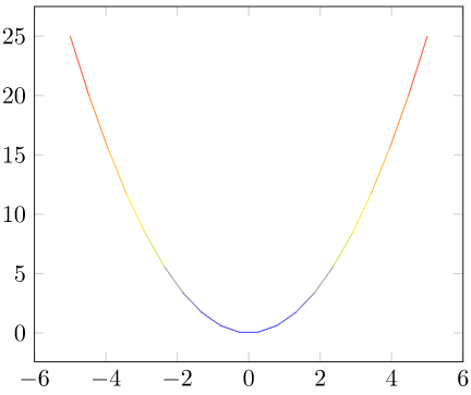
In this article we are going to see what a quadratic function is, its mathematical expression, its characteristics, how to graph it in the Cartesian plane and what it can be useful for in the development of games with examples in Unity.
Mathematical expression of a quadratic function
The polynomial expression of a quadratic function is:
It is commonly read “f of x”, being X the independent variable, a, b and c constant real numbers.
Characteristics of a quadratic function
Domain
The domain is the range of allowable values for the independent variable, commonly referred to as X.
In the case of the quadratic function the domain is the set of real numbers.
In other words we can choose any value of X belonging to the set of real numbers and we will find its corresponding value f (X).
The roots of a quadratic function are the values of x for which f (x) is worth 0, i.e. the points at which the function touches the abscissa axis (commonly the x-axis).
There can be three cases, the function has a root, i.e. there is only one value of x for which the function is worth 0.
The function can have two roots, i.e. there are two different values of x for which the function is worth 0.
The function may not have roots in the set of real numbers but in the set of complex numbers.
To calculate the roots of a quadratic function we use a formula commonly known as the Bhaskara formula.
Given the following equation:
The two values of x that satisfy this equation are given by:
The plus-minus sign ( ± ) means that they are two equations, in one we use the plus sign and get X1 and in another we use the minus sign and get X2.
As an observation, if what is inside the square root gives as a result a negative number it means that the equation has no solution in the set of real ones, in this case we see graphically that the parabola does not cut the axis of the abscissas.
Some examples in Unity of quadratic function
Draw parabolic trajectories
We might be interested in drawing parabolic trajectories through code, for example for particle systems, or to represent the possible trajectory a projectile can follow when launching it.
In the following video I show how a set of GameObjects follow a parabolic path described by two quadratic functions to which the parameters can be adjusted.
Observation 1: spheres of the same color follow the path defined by the same equation only that for one I take the constant a as positive and in the other as negative, for this reason they are reflected with respect to the axes.
Note 2: Notice that at the beginning and end of the video the value of a is 0, this means that the quadratic term is annulled and we are left with a linear function.
In physics there are many quadratic magnitudes that we might be interested in implementing in our game.
An example of this can be motion with constant acceleration, i.e. objects that move with velocity that changes linearly. For example, bodies in free fall by the action of gravity or vehicles that accelerate.
Some types of energy such as kinetic energy or elastic potential energy are proportional to the square of a magnitude.
Conclusion
The quadratic function is a polynomial function of order 2 whose graph in the Cartesian plane is a parabola.
The roots of the quadratic function are the values of x in which f (x) = 0 is fulfilled. We can use Bhaskara’s formula to find them.
A quadratic function can have two different roots, a root or not have roots in the set of real numbers. If a quadratic function does not have real roots, it does not graphically intersect the abscissa axis.
There are physical magnitudes as well as trajectories of accelerated bodies that can be described by quadratic functions, so it is useful to have knowledge about their characteristics and thus be able to implement them correctly in Unity.
Introduction
This article will function as the practical part of the previous article on Classes in Programming. We are going to solve an exercise on class structure and implement it in C# in Unity.
If you don’t know what a class is in programming it would be good if you saw the article I wrote on the subject before continuing.
Let’s see an example that occurred to me at the time of writing this article. It’s about modeling the behavior of a village that has inhabitants and these inhabitants can be workers or warriors.
I have highlighted what I consider to be key words in raising the problem, in principle it seems that at least we are going to need two classes to solve it, one for the village and one for the villagers, but we are going to consider the fact that both workers and warriors themselves are villagers.
Workers and Warriors will have common characteristics and behaviors that will be defined in the Inhabitant class and then the Worker and Warrior classes will inherit the characteristics and behaviors of Inhabitant.
A village has inhabitants so the Village class will have among its data one or more instances of the Villagers class.
I would like to mention that knowing the difference between classes and instance of classes is very important, but this article is not about that, just as it is not about inheritance.
At the moment the idea is that we are going to use the Inhabitant class to create all the inhabitant objects that we need, these objects will have their own values (for example different names or age) but they will respect the structure defined in the class.
Class Diagram
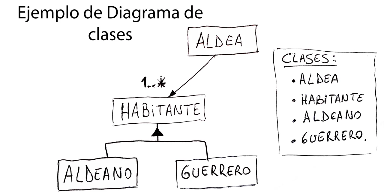
Then we said that we are going to use four classes, Village, Villager, Worker and Warrior. The Village class has among its data one or more instances of the Inhabitant class. Worker and Guerrero are a specific type of Inhabitant so inheritance will be used.
The class diagram in Figure 1 is based on the previous paragraph.
Fig. 1: Example of what a class diagram might look like in a project
In the diagram we observe a “1..*” above Inhabitant, this means that Village will have one or more Inhabitant objects.
In addition, we observe that the inheritance of classes is represented by an upward arrow toward the parent class.
Object Diagram
Once the classes that will be present have been defined, we think about their possible fields and methods. In this part it is good to reflect on the nature of the object we want to model, what its characteristics are, what information it handles and what its behaviour may be.
I’m going to make up some fields and methods for the classes because this practice of programming classes is more about the approach of class structure and its later implementation in Unity in C# language, but without going into details of what is going to be done with this.
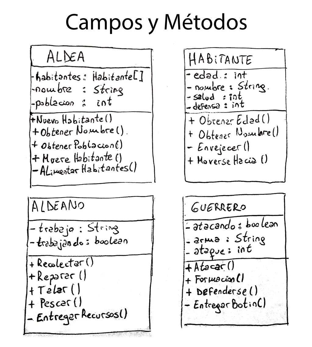
Figure 2 shows the object diagrams of the four classes.
Fig. 2: Using these boxes we indicate the attributes and methods, public and private, of the classes.
Now I am going to explain in detail how the boxes in figure 2 are interpreted.
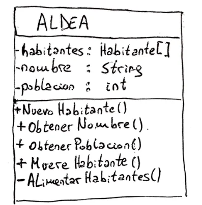
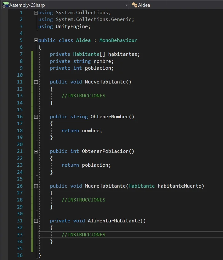
The Village Object
For this object I considered that every village has a name and a group of inhabitants, so for its fields I am going to use a collection of objects called “inhabitants”, a string called “name” and an integer called “population”. I place these fields at the top of the box as shown in figure 2.1.
Some methods of the object Village can be “NewInhabitant” which will be executed every time an inhabitant is born. “GetName” and “GetPopulation” will return the corresponding data (they are known as “Getters” and are useful for example to make statistics of all the villages we may have).
The “InhabitantDie” method can modify the population and remove the dead inhabitant from the collection of inhabitants.
Fig. 2.1: Object diagram for the Village class, where we see the fields and methods of the class.
Finally, the “Feed Inhabitants” method, which can go through the collection of inhabitants executing appropriate methods in each of them, or check the food reserve and subtract as many units as there are populations.
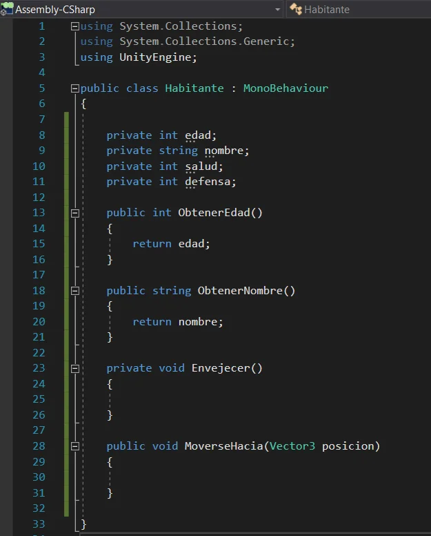
El objeto Habitante
Inhabitant will be the parent class (or superclass) of Worker and Warrior, in this class will be defined the behavior and data that have in common Workers and Warriors.
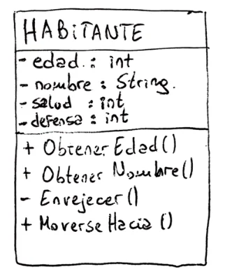
Every inhabitant has a name represented by a String, an integer for age, another for health and another for defense.
Fig. 2.2: Object diagram for the Inhabitant class, where we see the fields and methods of the class.
Among the methods of Inhabitant we have the “Getters” to obtain name and age, a private method to age and a public method for the inhabitant to move to a position.
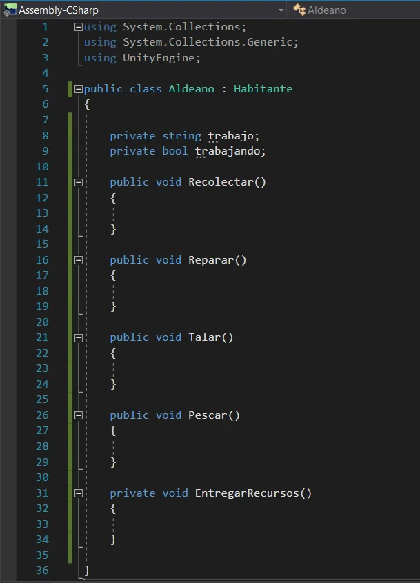
The Worker Object
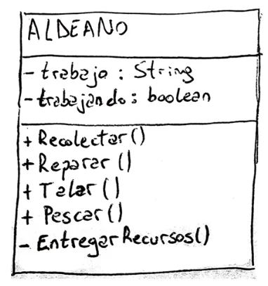
The Worker Object is a more specific case of the Inhabitant class, between its fields we have a string that indicates the name of the work and a boolean variable to know if it is working or not.
Worker methods are related to what your activities could be, for example Collect, Repair, Drill, Fish and also a private method for you to deliver the resources it has obtained. This last method can be executed internally by Worker for example when it is at the limit of its collection capacity.
Fig. 2.3: Object diagram for the Village class, where we see the fields and methods of the class.
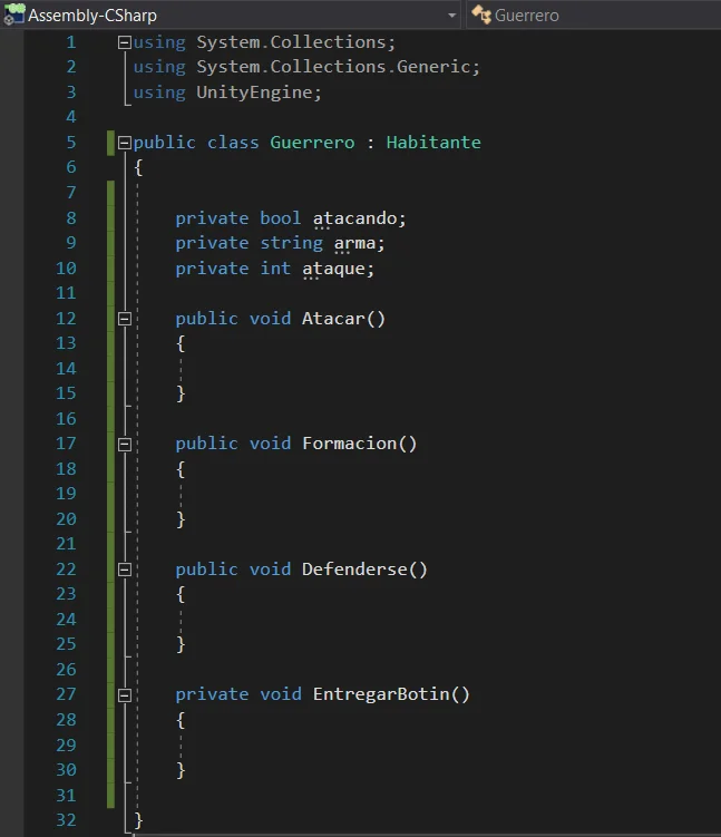
The Warrior Object
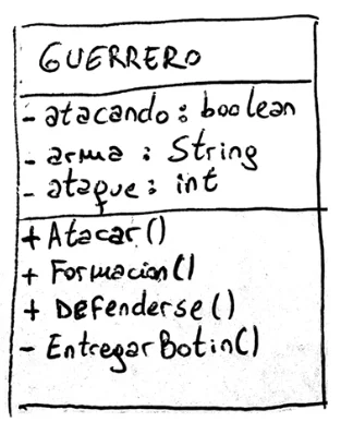
The Warrior class is a more specific case of the Inhabiting class.
A Warrior may or may not be attacking for which we use the Boolean variable “attacked”, has assigned a weapon represented by a String and has certain attack points represented by an entire variable.
Among its methods are Attacking, Formation, Defending, and a private method to deliver the booty he got after a successful battle.
Fig. 2.4: Object diagram for the Warrior class, where we see the fields and methods of the class.
Implementation in Unity
Now we move on to the good part, let’s take the class diagram and the object diagram from figures 1 and 2 and use them as a reference for creating classes in Unity.
Before you start you might need to know how to use Unity, here on the page I have a couple of series, one called “Unity Fundamental Series” and the other “Labyrinth Game“, the first one has specific themes and the second one is a mini project. You can find all the articles using the navigation menu and there are also the videos in the channel.
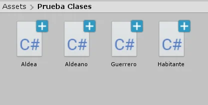
Let’s go on, in a Unity project we created the four classes from the diagram in Figure 1.
Fig. 3: Create the necessary C# scripts according to the class diagram in figure 8.
By convention, class names begin with a capital letter and CamelCase is used if the class name has more than one word. For example the class “Long Range Weapon” could be written “Long RangeWeapon”, better still if we get used to using the English name “LongRangeWeapon”.
A clarification, as seen in the article: “What is a Class in Programming“, when creating a new class in Unity, it will inherit from MonoBehaviour, which will allow Unity to consider it in its internal cycle. Let’s leave this inheritance as it is, even if we haven’t made it explicit in the class diagram in Figure 1.
If we wanted to make a more accurate diagram we should place the MonoBehaviour class and make both Village and Inhabitant inherit from it.
As a clarification it is good to say that our classes are going to be MonoBehaviours, however it does not make sense to pose an extremely complete class diagram since MonoBehaviour inherits the Behaviour class, which in turn inherits the Component class, who finally inherits the Object class. It is not necessary to go that far, we must focus on what is important to solve our problem.
The Village class
To write the corresponding code in the Village class we must look at the Village Object diagram and simply know the syntax of the object-oriented language we are going to use, in this case C#.
In figure 4 we see how the diagram in figure 3.1 is implemented using the C# language in Unity.
Notice how the names, data types, and visibility indicated in the object diagram are respected.
Fig. 3.1: Object diagram for the Village class, where we see the fields and methods of the class.
Fig. 4: We define the necessary attributes and methods, taking into account the boxes in figure 9.
This is the idea of practicing Classes in programming, creating classes in Unity based on an analysis of the problem and diagrams of classes and objects.
We are not going to write anything in the methods because it is something that depends on the purpose of the solution we are proposing.
The Inhabitant Class
Fig. 2.1: Object diagram for the Inhabitant class, where we see the fields and methods of the class.
Fig. 5: We define the necessary attributes and methods, taking into account the boxes in figure 9.
The Worker Class
Fig. 2.1: Object diagram for the Village class, where we see the fields and methods of the class.
Fig. 6: We define the necessary attributes and methods, taking into account the boxes in figure 9.
The Warrior Class
Fig. 2.1: Object diagram for the Warrior class, where we see the fields and methods of the class.
Fig. 7: We define the necessary attributes and methods, taking into account the boxes in figure 9.
Conclusion
In this practice of Classes in Programming, we have seen how, from the point of view of a problem, we propose a structure of classes to model the behaviour of the elements.
We represent the structure of classes using a Class Diagram in which we show what is the relationship that exists between them.
The Classes will have their members, i.e. Fields and Methods, we can represent them using Object Diagrams, in which we show names and types of data for the Fields and the methods that the class will have. Also the visibility of each one.
All of the above is independent of the programming language, it is about intuitively modeling an object-oriented solution.
To implement it in Unity in language C# we will have to know the own syntax of the language, nevertheless it is extremely interesting to know that this same one could be reused for example for an Android application using language Java in Android Studio.
Introduction
In this article we are going to see what is a CLASS in programming, what are its components, class diagrams and of course we are going to see examples in C# using Unity.
If you already know about this topic I invite you to see the practical part of this article in which I pose a problem to create a class structure, make diagrams and then program the solution in Unity.
The concept of Class is linked to object-oriented programming.
When we program in C# using Unity, when we create a new Script we automatically create a class that is called the same as the Script.
The terminology we use when referring to a class probably changes depending on the bibliography or the teachers, but if we can grasp the basic idea we can use this knowledge to create solutions for our projects.
What is a class in programming?
A class is a tool we have to model programming objects, make them behave as we want and make as many copies of them as we need.
For now let’s just think of it as code that is encapsulated in a programming script.
How to define a programming CLASS
Depending on what we are doing, creating a class will be done one way or another. In general what we will do is create an instruction file with the extension of the programming language we are using and whose name will coincide with the name we give to the class in its declaration.
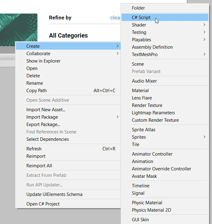
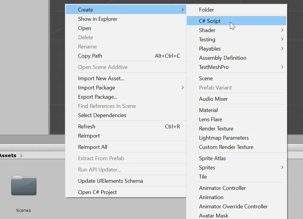
In general, development environments simplify the process of creating a class. For example in Unity from the project folder we can right-click and use the menus to create a new C# Script, as shown in figure 1.
Fig. 1: From the project window you can create new C# Script.
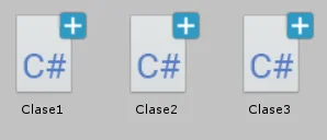
To show some examples of classes in Unity, I am going to create the three Scripts that are observed in figure 2.
Fig. 2: I am going to create three Scripts to exemplify the classes in programming.
Example 1, default class
When we create a new script, when we open it we are going to find some code already written.
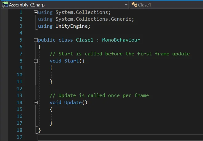
In figure 3 we can see that in the first three lines are imported some libraries that will allow us to access the functionality of the Unity engine.
Then it is observed that a class called “Class1” is defined, the definition of the class begins in line 5 and ends in line 18 with the closing of the key.
Something we also see is the “MonoBehaviour” to the right of the class name, this means that our “Class1” is going to be an extension of the MonoBehaviour class, which is known as inheritance.
Inheritance is a great topic and we are not going to delve into this article, for the moment think that if a class called Class 1 inherits the class MonoBehaviour, means that Class 1 is itself a MonoBehaviour but with more specific functionality.
It’s like thinking about dogs and cats, these are different species but share certain characteristics such as the number of legs and also have similar behaviors such as walking, running, eating and breathing. This means that we can group them for example in a class called SerVivo, Animal or Quadruped (no accents are used in programming).
MonoBehaviour is like the basic class of GameObjects in Unity and allows these to be automatically initialized through the Start method and also automatically runs the Update methods (also defined automatically when creating a class, lines 8 and 14 of figure 3) and FixedUpdate for example. For more details about the MonoBehaviour class you can take a look at the Unity API.
Fig. 3: The first example shows what a new script looks like. This is the Class1 class that inherits the MonoBehaviour class.
Example 2, Object subclass
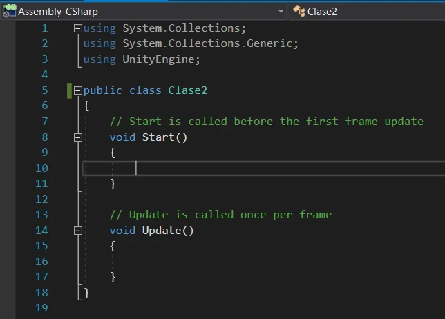
In the example in figure 4 the inheritance of MonoBehaviour has been removed, this implies that Class2 will inherit implicitly from the “Object” class, which is probably the mother of all the classes we are going to use in Unity.
By removing the MonoBehaviour the green comments in lines 7 and 13 of figure 4 are no longer true. These Start and Update methods will not be executed automatically.
It is not normally used in Unity this type of classes that derive directly from Object.
Fig. 4: In the second example we eliminate the inheritance of MonoBehaviour, which means that Class2 inherits Object.
Example 3, subclass of another class
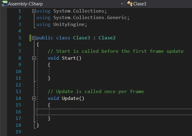
This example is similar to example 1, we can make classes that derive from other classes (inheritance of classes), not necessarily MonoBehaviour but any UnityEngine class or that we have created.
In figure 5 we see that Class 3 inherits Class 2.
Fig. 5: La clase Clase3 hereda de la clase Clase2.
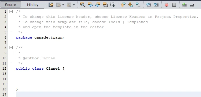
Example 4, Java classes
Usando NetBeans IDE hice un par de clases en Java para mostrar, aunque Unity no usa Java, es interesante ver las similitudes y diferencias.
Las siguientes clases serán análogas a las creadas en los ejemplos 2 y 3.
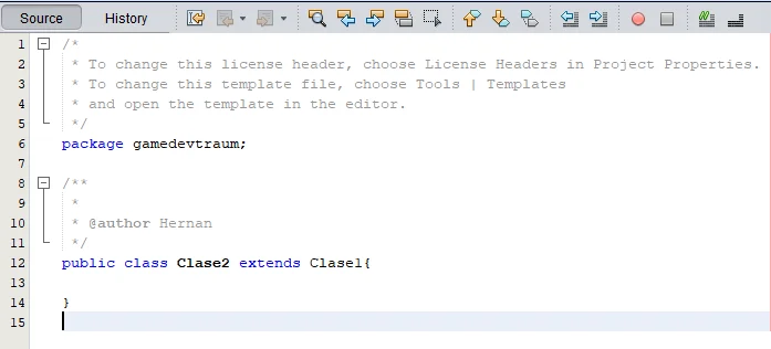
La Figura 6 muestra una clase llamada Clase1 derivada de Objeto mientras que la Figura 7 muestra una clase llamada Clase2 derivada de Clase1.
Fig. 6: Definition of class in Java using NetBeans IDE.
Fig. 7: To indicate that inheritance is used the word extends.
Components or members of a class
The classes in programming are used to model objects that we want to fulfill a function.
Fields
It is the data that the class has, they can be variables or even instances of other classes.
For example, a class called “Auto” might have a boolean variable to indicate whether it is on or off. A float variable to indicate the speed and another for the remaining fuel.
We could use a three-dimensional vector (“Vector3” class in Unity) to determine the speed and direction of motion.
Also the class “Auto” could have between its fields the instance of another class called “Motor”, which in turn will have its own members defined.
Methods
Methods are those that provide functionality to a class, allowing it to perform tasks, manipulate its fields and interact with other classes.
Returning to the example of the “Auto” class that has among its fields the “Motor” class.
Suppose Auto has a method called “Accelerate” that progressively increases the speed of the vehicle.
Class Diagram
A useful tool when it comes to reflecting the structure of classes that we will make to propose a solution is the class diagram, in which we will show the different classes, the relationship that exists between them and we will show the inheritance of classes that may exist.
In figure 8 we see an example of a class diagram based on the practical exercise of classes in programming.
Fig. 8: Example of what a class diagram might look like in a project
Objects Diagram
Once we have defined the classes that will be present we think about their possible fields and methods, in this part it is good to reflect on the nature of the object we want to model, what are its characteristics, what information it handles and what can be its behavior.
We can represent the fields and methods of a class using “Object diagrams” that in general are drawn with a box for each class, indicating fields and methods using the names that we are going to give them in the script and separated by a line (in my case to the methods I add the symbols “( )” to indicate that they are methods). For the fields we also indicate the type of data.
Another thing we can indicate is the visibility of fields and methods, using a “+” sign for fields and public methods and the “-” sign for fields and private methods.
Figure 9 shows Object diagrams for the 4 classes of the class diagram in Figure 8.
Fig. 9: Using these boxes we indicate the attributes and methods, public and private, of the classes.
Conclusion
In this article we have seen what a class is in programming, it is like a template that will allow us to create instances of objects that will have the attributes and methods that we have defined in the class.
Classes have defined within them fields and methods that together will define their nature and behavior.
The class diagram helps us to represent the relationship that exists between our classes.
The object diagram allows you to represent the fields and methods of a class along with their visibility.
IMPORTANT UPDATE
I have created a more complete and simple to use solution, it is a Unity package to download and import, with a prefab that when dragged into the Canvas automatically produces the fade effect, you can customize several parameters in the inspector. You can download the Unity Package in the link below:
In the following video we see the FADE IN/OUT effect for Unity
In this article we’re going to see a simple way to darken the screen in Unity using an image component. This can be very useful for example to use as a transition in a scene change.
In the video below I explain how to use it, but I do not explain how it works, if you are interested in knowing about programming level operation continue reading this article.
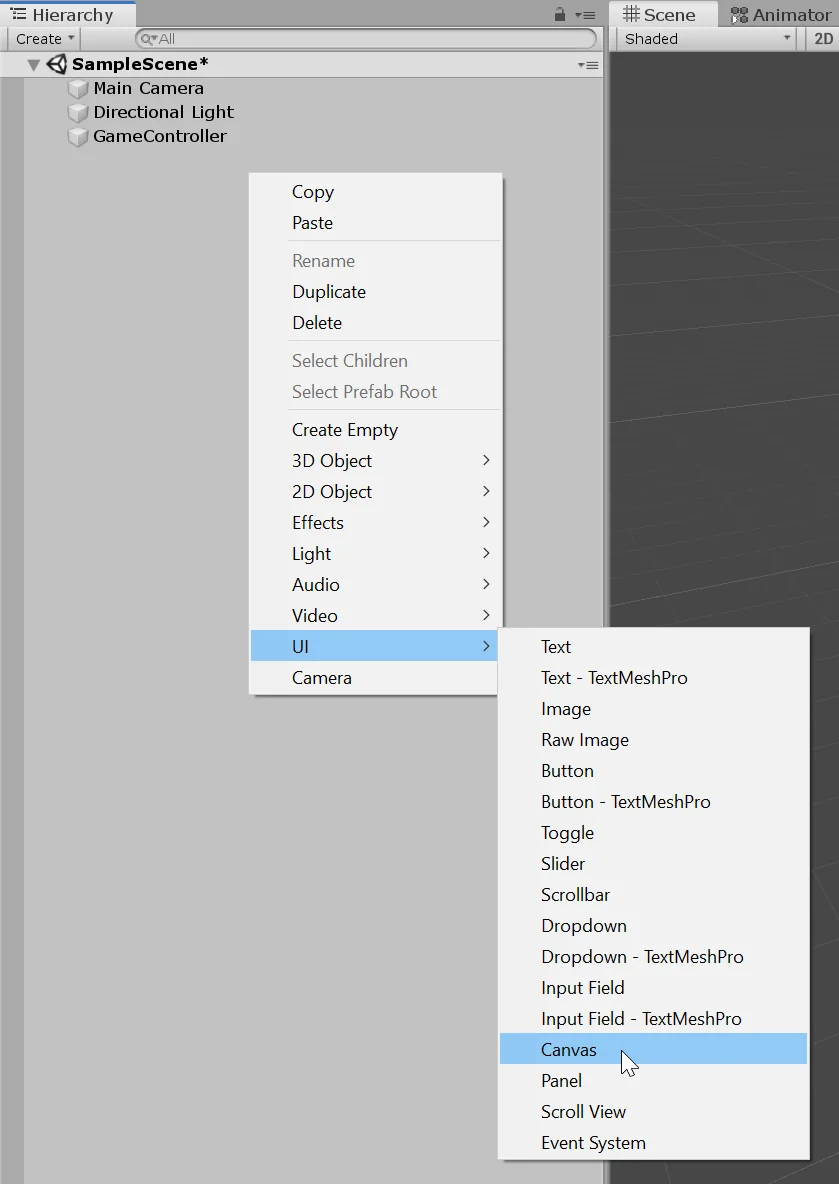
We will create all the elements necessary to solve the problem. First an empty GameObject that we will call “GameController” and a GameObject type Canvas that is the one that will contain all the elements of the graphical interface.
Fig. 1: We start by creating an Empty GameObject with the name “GameController”.
Fig. 2: We created Canvas to show graphical interface elements.
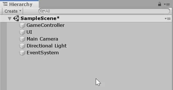
In figure 3 we see these elements created and placed at the beginning of the hierarchy.
Fig. 3: I give the Canvas the name “UI” and place the control object and the canvas in the first position.
Image to dim the screen
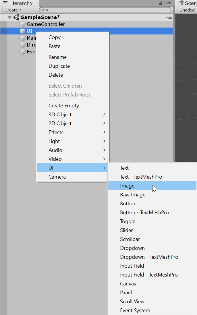
The next thing we do is create an Image as a child of GameObject UI. This image will be used to block the vision of the camera.
Fig. 4: Right-click on the UI object to create an image.
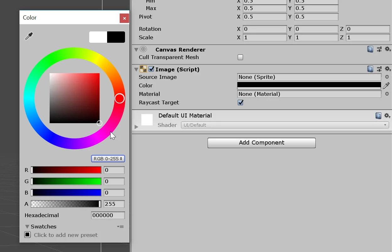
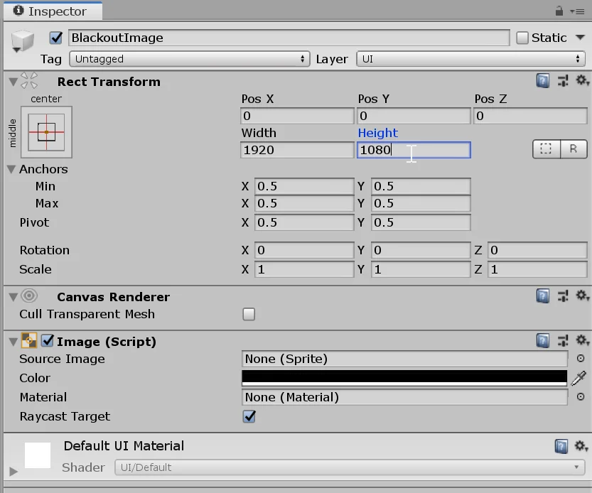
In the inspector in the image component we make the color black.
Fig. 5: We make the color of the image black.
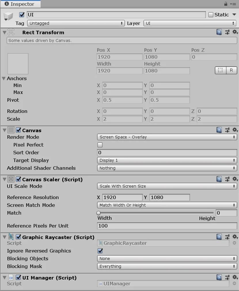
Canvas Scaler Setup
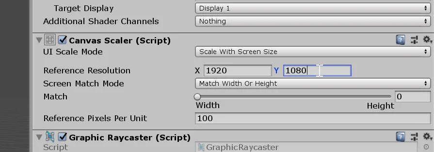
Let’s go to the GameObject UI and in the inspector, in the component CanvasScaler we select the mode “Scale with screen size” in the field “UI Scale Mode” (figure 6). With this we can make the elements of the graphical interface modify their size according to the size of the screen.
Fig. 6: Configure the CanvasScaler object to fit the width of the screen.
For the reference resolution we are going to use 1920 x 1080 pixels, which is known as FullHD resolution.
The configuration of the CanvasScaler should be done at the beginning, before placing the elements of the graphical interface. Otherwise we will have to modify all the elements again to adjust them to the new configuration.
Fig. 7: Introducing FullHD resolution, 1920 x 1080.
We return to the GameObject image and adjust its size to 1920 x 1080 to cover the entire screen. If everything works well the screen should look like in figure 9.
Fig. 8: We adjust the size of the image so that it covers the whole screen.
Fig. 9: We should see the background of the scene obstructed by the image.
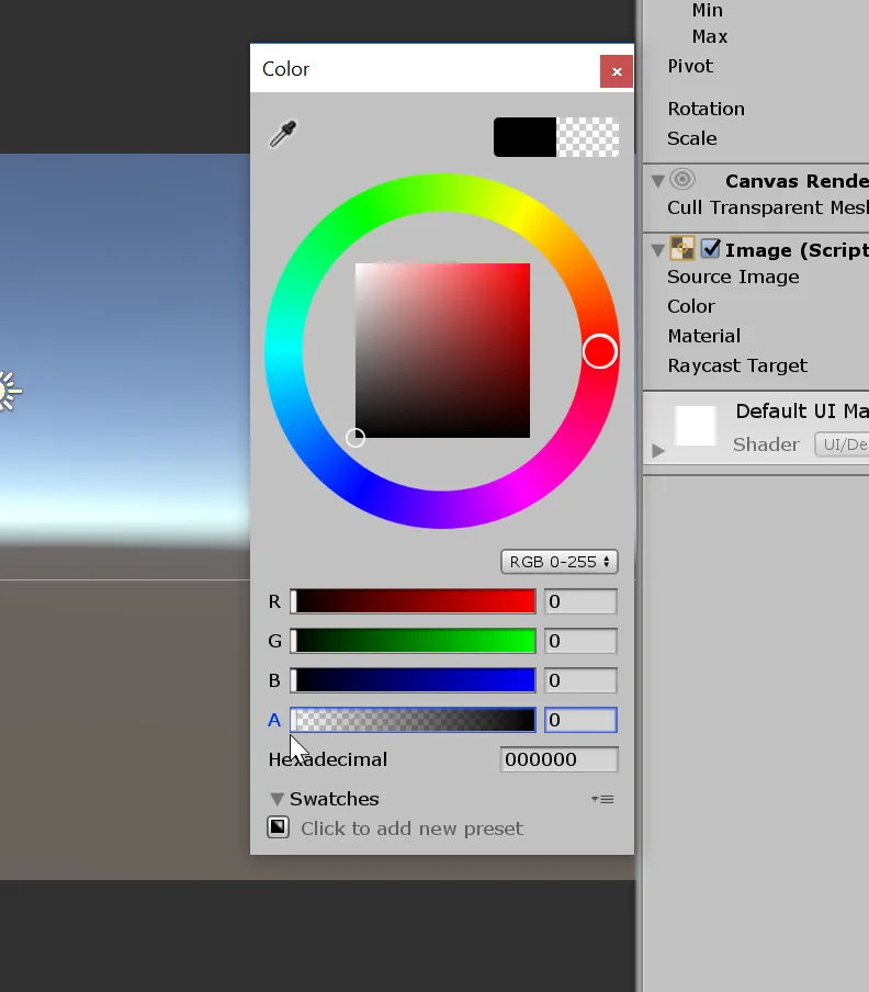
In the black color of the image we are going to make the Alpha component 0, this way it will be transparent.
Fig. 10: In the color of the image we set the alpha value to 0.
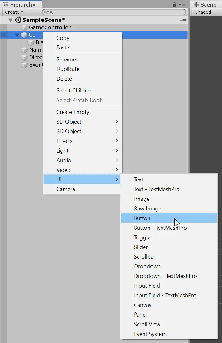
Now we are going to create a couple of buttons to execute the functions that we will later define in the Scripts.
Buttons
Fig. 11: Create a button to activate the black screen function.
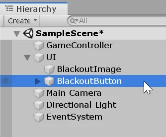
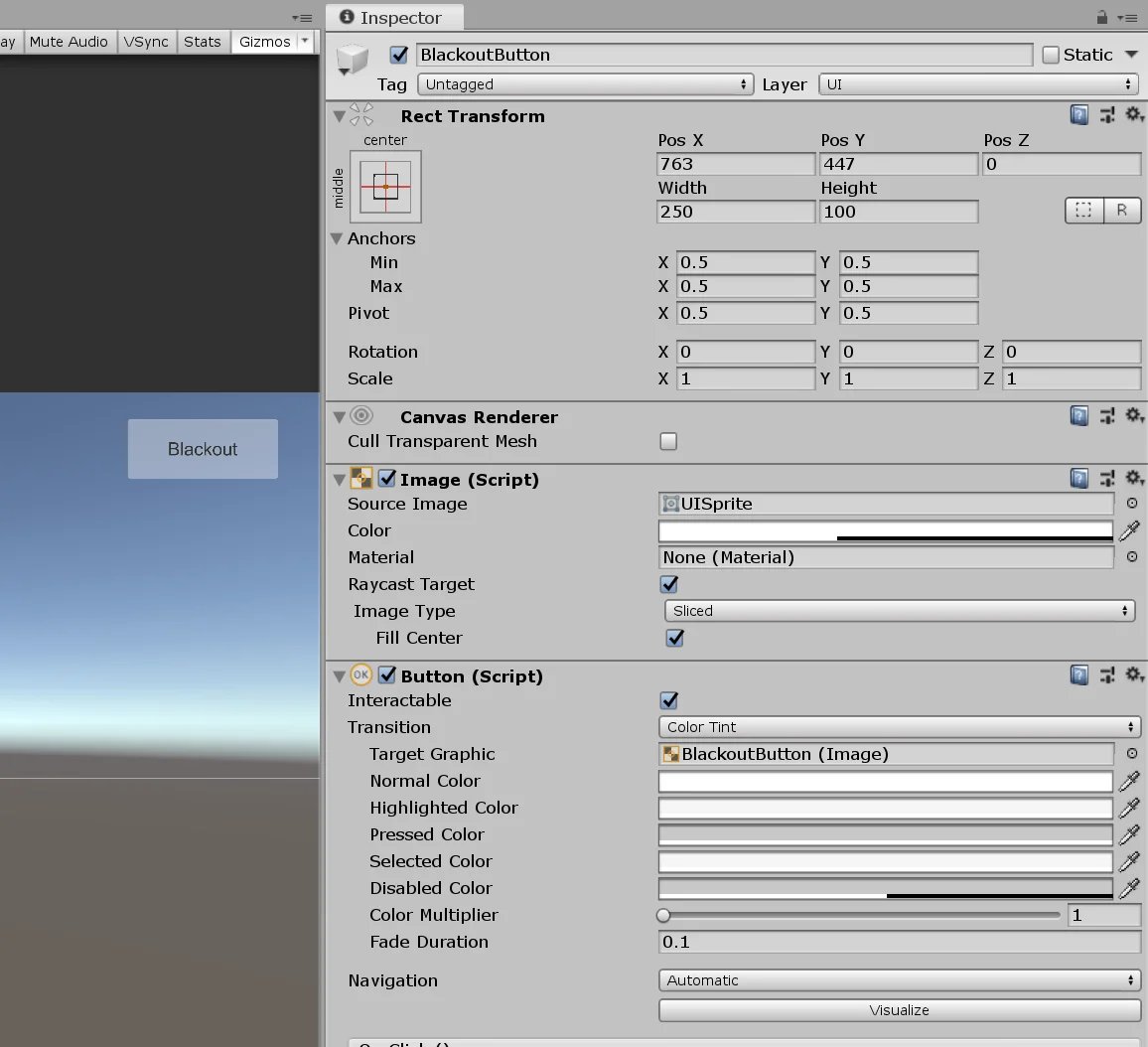
We are going to call the first one BlackoutButton which is the one that is going to take care of darkening the screen completely.
Fig. 12: The button will be called “Blackout” as well as the function.
We adjust the sizes and colors to taste.
Fig. 13: We adjust the parameters of the button to taste.
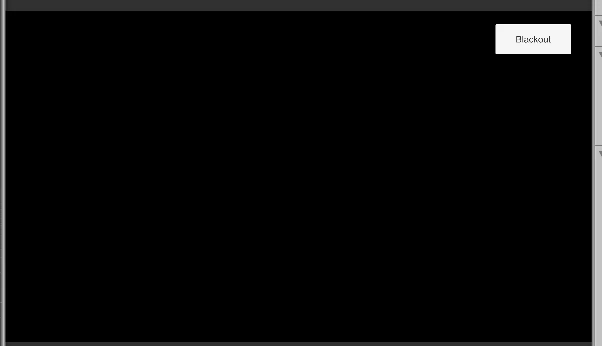
We must make sure that the button is below the image in the hierarchy, that way the black screen will be drawn first and then the button, as we see in figure 14.
Fig. 14: The button must be visible even with the black screen.
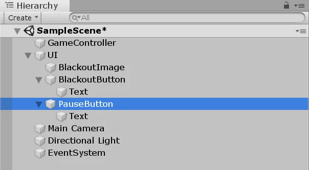
Once we configure the Blackout button we are going to duplicate it and give it the name “PauseButton”, we accommodate it where we like on the screen. In figure 16 is my result.
Fig. 15: Duplicate the blackout button, move it down and give it the name “Pause”.
Fig. 16: With this the scene is finished.
C# Scripts
Now we are going to create two C# Scripts, the first one we will call “GameController” and the second “UIManager”.
Fig. 17: Let’s create two Scripts to control the elements.
Fig. 18: One script will be named “GameController” and the other “UIManager”.
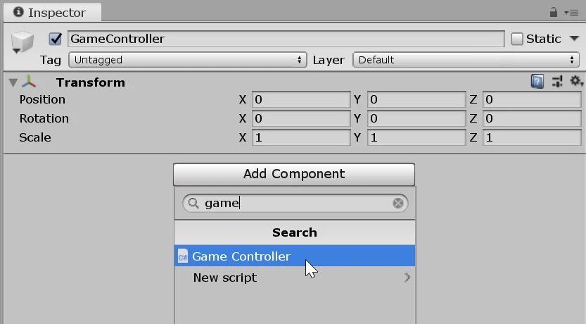
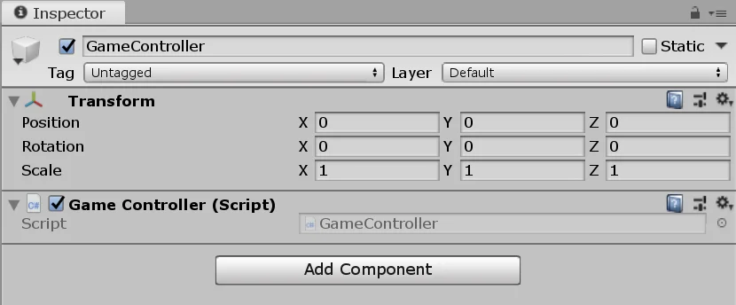
The GameController Script is assigned to the GameObject with the same name. We can select it and drag it to the inspector or use the “Add Component” button.
Fig. 19: Select the GameObject GameController and use AddComponent to assign the GameController Script.
Fig. 20: The GameController Script is now a component of the GameObject.
The UIManager Script is assigned to the GameObject “UI”.
Fig. 21: Select the GameObject UI and with AddComponent assign the UIManager Script.
Fig. 22: The UIManager Script is now a component of the GameObject.
GameController Script
The GameController Script is responsible for indicating when the screen should be darkened and at what opacity value it should be set. It does not control the image object directly, this is the responsibility of the UIManager.
GameController will have two functions, one will be the Blackout function which will tell the UIManager to completely darken the screen and the other will be the Pause function which will cause the screen to darken 50%.
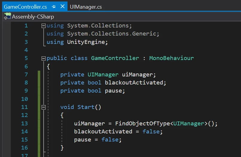
Fields and Initialization
We are going to define a UIManager type object to have the reference of the UIManager Script assigned to the GameObject UI in order to be able to access its public methods.
We’re also going to need two boolean variables to indicate if blackout and pause are enabled.
In the Start method we find the reference of the UIManager Script assigned to the GameObject UI with the instruction 13 shown in figure 23. Then we put in false the boolean variables.
Fig. 23: Fields and initialization in the GameController Script.
Methods
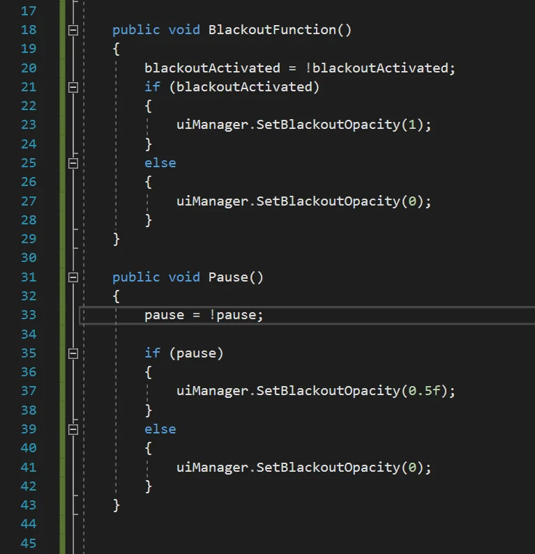
So that the Script fulfills the two functions that we said, we are going to define two public methods, one will be called “BlackoutFunction” and the other “Pause”. These methods will be executed when pressing the buttons of the graphical interface.
In the BlackoutFunction method the first thing we do is invert the state of the boolean variable blackoutActivated, so if it was in false now it’s going to be true and visceversa.
Then we check the state of that variable and we will execute a UIManager Script method with the appropriate parameter. At this point we have not yet written the “SetBlackoutOpacity” method of UIManager, so if you write lines 23 and 27 of figure 24 you will have an error.
In the Pause method we are going to do the same thing but instead of completely darkening the screen we are going to make it darken to half the opacity.
Lines 23, 27, 37 and 41 can be written after working on the UIManager Script.
Fig. 24: Blackout function and Pause function of the GameController Script.
UIManager Script
This script will control the parameters of the image to dim the screen.
In order to do so, it will constantly execute the Blackout function that will gradually modify the opacity of the image. In addition it will have a public method called “SetBlackoutOpacity” that will allow to tell the level of opacity wished, 0 means invisible black screen, 1 is completely visible black screen.
Fields and Initialization
To solve the behavior we are going to need an Image type object that we call “blackoutImage” and that we will mark with “SerializeField” so that it appears in the inspector.
We define a float called “blackoutOpacityChangeStep” to indicate the magnitude of opacity change in time, we also serialize it. Finally we define a float called “blackoutTargetOpacity” that will be the value that the opacity will tend to approach in each step of time.
In the Start method we make the objective opacity 0. We can see all this in figure 25.
Fig. 25: Fields and initialization in the UIManager Script.
Methods
We are going to define two methods, Private Blackout and Public SetBlackoutOpacity. Within the FixedUpdate method we will call the Blackout method, as shown in figure 26.
In the Blackout method we first read the current state of opacity of the image object (instruction 29 in figure 26).
If the opacity of that object is less than the objective opacity we will make it increase, if the opacity of the object is greater we will make it decrease. We achieve this with the “if” and “else if” of lines 31 and 39 respectively.
In order for the opacity to gradually increase or decrease we will create a new color to which we assign the same RGB components but to the alpha parameter we add or subtract the float “blackoutOpacityChangeStep”. In figure 26 we can see how to solve this.
The SetBlackoutOpacity method will be public and will take a float value as parameter. Simply assign this value to the variable “blackoutTargetOpacity”, as shown below in figure 26.
Fig. 26: UIManager methods to darken the screen at runtime.
We change the opacity value in the FixedUpdate method because we don’t want it to happen instantly but gradually to have a Fade In/Out effect.
Last settings
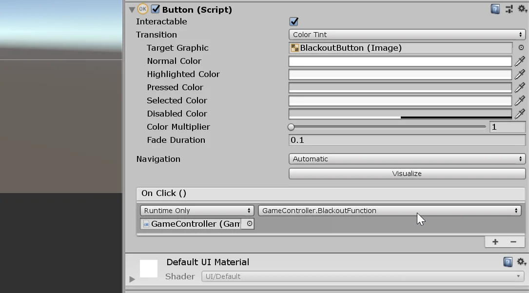
To be able to execute the GameController methods using the buttons, we have to do it in the OnClick() function of the button component.
Drag the GameObject GameController to the field under “Runtime Only” and using the drop-down menu select the “BlackoutFunction” method.
If it doesn’t appear in this list, we probably haven’t defined it as public.
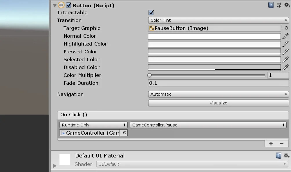
With the button of Pause we do the same thing only that choosing the method Pause of GameController.
Fig. 27: In the Blackout button we execute the Blackout method of GameController.
Fig. 28: In the Pause button we execute the Pause method of GameController.
Finally select the GameObject UI and drag the GameObject BlackoutImage (with the image component, see figure 12) to the “Blackout Image” field. For the float “BlackoutOpacityChangeStep” we enter the value 0.1.
The result is shown in Figure 29.
Fig. 29: For the UIManager component we enter a value for the changeStep parameter.
Conclusion
In this article we saw a way to darken the screen in Unity. To achieve this we used a black image and modified the value of Alpha, which determines the opacity of the color. If the alpha is equal to 1 the color is totally opaque, if it is equal to 0, the color is totally transparent.
We configure two buttons to execute public methods of the GameController Script, which tells the UIManager object how should be the opacity of the black screen. UIManager finally makes the changes in the alpha value of the black screen.
Introduction
In this article we see a prototype of artificial intelligence for enemies in Unity.
These enemies will be in different states according to what happens during the game. The states are “Guard”, “Searching”, “Attacking”, “Covering”.
The idea for this prototype came about because a person wrote to me in the channel’s comments asking how you could get enemies to detect you, alert each other, warn others and attack.
To answer your question I created a project at Unity proposing an approach to the problem and made a video explaining how this prototype of artificial intelligence for enemies worked. You can see it below.
Download project files
You can download the project files to import and view the scripts in detail.
What are we gonna do with this?
At the moment it’s just a prototype that I made on a weekend and that meets the problem I was posed.
However everything can be improved, I am thinking of creating a more complex system based on this, improve the code, modularize more, create a better model for the weapon, separate the range of vision of the Enemy Script, improve in general the individual states.
The word “bit” comes from “binary digit”
Introduction – Numerical Systems
Before going into the main topic which is bit in computer science, let’s start from a mathematical approach.
A digit is a quantity of one figure that has a value and occupies a position in some numerical system. Let’s take as an example the decimal system that we use on a daily basis. This system is composed of 10 symbols that we call numbers (0,1,2,3,4,5,6,7,8,9). Each of these symbols has a value assigned to it and given two different numbers we can order them for example from least to greatest.
It is also said that the decimal system is a “positional system“, that is to say that a digit acquires value according to the position in which it is located. This is something we are taught at a very early age, the subject of “units“, “tens” and “hundreds“. The values 1, 10 and 100 are composed of the same digit 1, but they are not worth the same because that digit is in different positions. In other words the position in which a digit is found will have an associated weight, a 1 in third position is worth ten times more than a 1 in second position and one hundred times more than a 1 in first position.
Once a positional number system such as decimal has been established, we can begin to construct operations between numbers such as addition, subtraction, multiplication and division.
Are there numerical systems other than decimal?
The use of the decimal system is centuries old and it is thought that its origin lies in the fact that human beings are born with ten fingers. It is the numerical system that is mostly used worldwide, however nothing prevents us from using any number of symbols to establish a positional numerical system, for example if instead of using 10 symbols we use 8 we have the octal numeral system, on which the same mathematical operations of the decimal system are also defined.
Let’s think about the following example, in the decimal system the operation 9+1 gives as a result 10, where the 1 that is in the second position we know that it has a value or weight of ten. If we take this same example to the octal system, in which we have the numbers (0,1,2,3,4,5,6,7), the operation 7+1 gives as a result 10, where the 1 in the second positionhas a value or weight of eight.
Another known system is the hexadecimal system that has 16 symbols (0,1,2,3,4,5,6,7,8,9,A,B,C,D,E,F), in this case the operation F+1 results in 10, where the 1 in the second position has a value of 16.
Another number system can be the binary system which is the one that interests us in this article, the binary system is composed of two symbols, zero and one, in this system the operation 1+1 results in 10, in which the 1 that is in second position has a value of 2. On the binary system can also be performed the operations of addition, subtraction, multiplication and division, but it has also been developed Boolean algebra that defines logical operations between binary numbers as the operations CONJUNCTION (AND) and DISJUNCTION (OR). And finally we come to the objective of this article, reiterating the opening sentence:
A “BIT” is a digit of the binary system.
What is a Bit in Computer Science?
In computing, the “bit” is the basic unit of information, which allows us to distinguish between two states.
Bits are grouped together to form binary words. A binary word of 8 bits is known as a Byte and allows us to represent 256 different states.
The processors in conjunction with RAM and ROM perform operations using binary words.
So by using bytes (which are made up of bits) it is possible to represent increasingly complex information, not only numerical, but also text, sounds, images, and to perform logical and mathematical operations on that information.
For example, using 3 bytes we can represent any color in the RGB system, one byte for the red channel, one for the green channel and one for the blue channel.
Another example could be that using a byte we can represent a character, then a sentence will occupy a space in memory proportional to the number of characters that compose it.
What is the difference between BIT and BYTE?
Bit and Byte are two terms that are often confused or even used as synonyms, so let’s emphasize this. As we saw earlier, a BIT is a binary digit that can have a value of zero or one, while a BYTE is an ordered arrangement of EIGHT BITS. A bit allows us to represent two different states while a BYTE, being a combination of EIGHT BITS allows us to represent 256 different states, 2 raised to the 8 possible combinations.
The size of Information
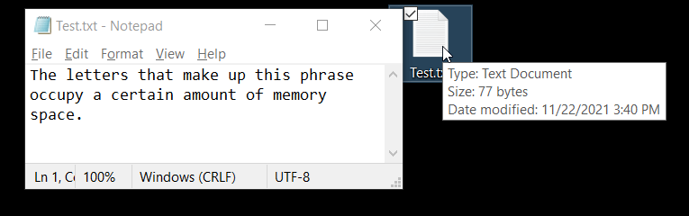
I invite you to do a little experiment to see how much space information takes up in computers. The experiment consists of opening Notepad and pasting the following sentence without the quotation marks:
“The letters that make up this phrase occupy a certain amount of memory space.”
The previous phrase has 77 characters, take a look of the size of the .txt file.
Fig. 1: A txt file with 77 characters has a size of 77 bytes.
This is not always accurate because a text file does not store only characters, but also information about the format to display those characters. In addition, programs can use compression methods to represent the same information in a more compact form, however in the case of the notepad, the weight of the information is usually proportional to the number of characters, especially if there are only common characters.
What is a Bit at the Hardware level?
It is said that computers work with ones and zeros, this is true at a theoretical level, but physically the bits are implemented with voltage levels, think of the lamp in a room that is turned on or off with a switch, when the switch is open, electricity does not flow and the lamp is off, when the switch is closed, electricity flows and the lamp is turned on, this example is similar to what happens inside the digital microchips, where there are extremely small switches (the size of dozens of atoms and every time they try to make them smaller) that open or close in a controlled manner, ie prevent the passage of electricity or allow it, in other words at the output of that switch we can have a 0 or a 1. These small switches are called TRANSISTORS.
Microprocessors are systems made up of millions of transistors. Using transistors it is possible to create logic gates, from the most basic gate which is an INVERTER that implements the logical operation NOT, that is to say if the input is 0 the output will be 1, to more complex gates such as the XOR gate, that given two input bits, the output will be 1 if and only if one of the inputs is 1. In addition these logic gates are grouped in increasingly complex digital systems to form flip flops, counters, adders, shift registers or memory blocks.
RAM is another example, a block of volatile memory, which stores bits temporarily to assist the processor with its tasks.
The hard disk stores bits in the form of magnetic fields using the magnetic hysteresis property of some materials, while solid state disks store information in flash memory blocks, with no moving parts.
Conclusion
A bit is a binary digit that can be worth 0 or 1, it is part of a numeric system analogous to the decimal system we use, the binary system, in which instead of having 10 numbers, we have two.
The bit is the basic unit of information used in computing. By grouping bits into binary words, all kinds of data such as numbers, text, images or sounds can be represented, i.e. information can be digitized.
The bit is a concept that is applied at the software level to analyze the information and logical operations that are performed. In microprocessors this translates physically to voltage levels or magnetization in the case of magnetic hard drives.
Introduction – Project Setup
In this article we will learn how to use console messages to analyze how our code works and eventually detect and correct bugs.
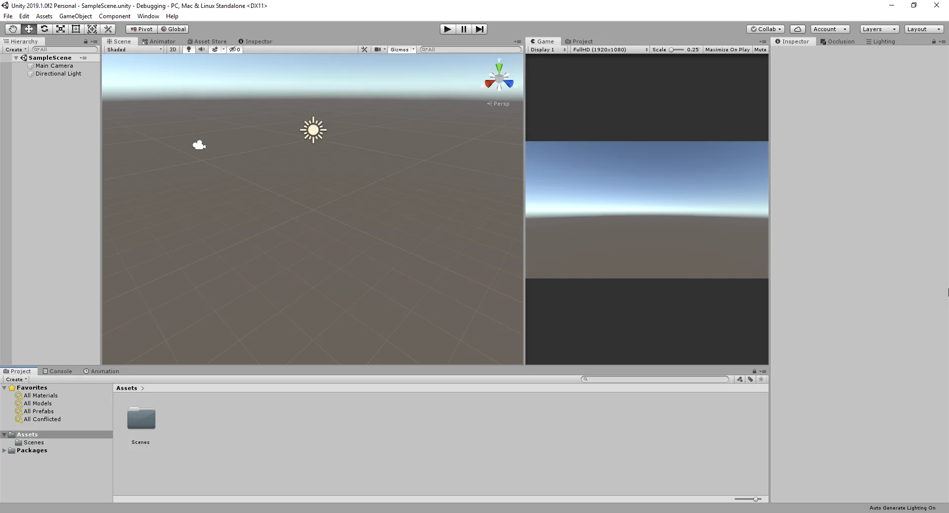
To start we are going to create a new project in Unity, in my case I am going to call it Debugging.
Fig. 1: Initial scene to study the Debug.Log method.
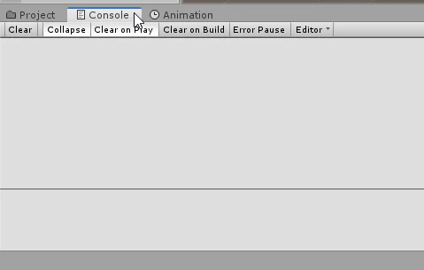
In the process of detection and correction of bugs we are going to use mainly the console of Unity, in that window will print messages that we will strategically place in our code.
Fig. 2: Console tab in Unity 3D.
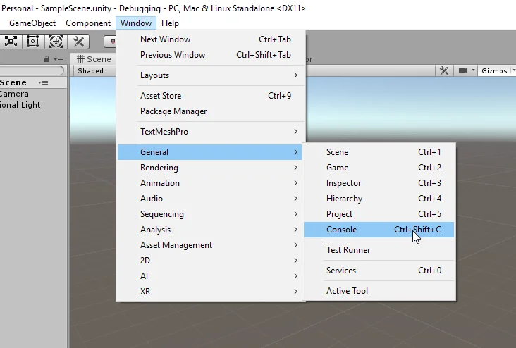
If the console window is not active, you can open it from the Window tab as shown in figure 3.
Fig. 3: Path to open the console in Unity 3D.
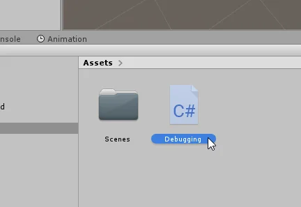
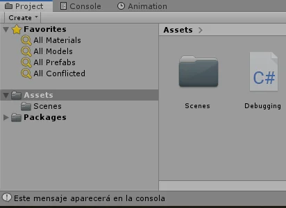
The next step is to create a new C# Script, we can do it from the project window as shown in figure 4. I’m going to give it the name “Debugging”.
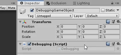
For the code of our Script to run in general it is not enough to create the Script, it must also be assigned to at least one GameObject of the hierarchy. Let’s create an Empty GameObject and give it a meaningful name.
Then with that GameObject selected we drag the Script towards the inspector to assign it (figure 8).
Fig. 6: Create new Empty GameObject in the hierarchy.
Fig. 7: We give the GameObject a name.Fig. 8: The Script created previously in the inspector is assigned.
Fig. 9: The Debugging Script has been assigned in the inspector.
Programming C# Unity – Debug.Log
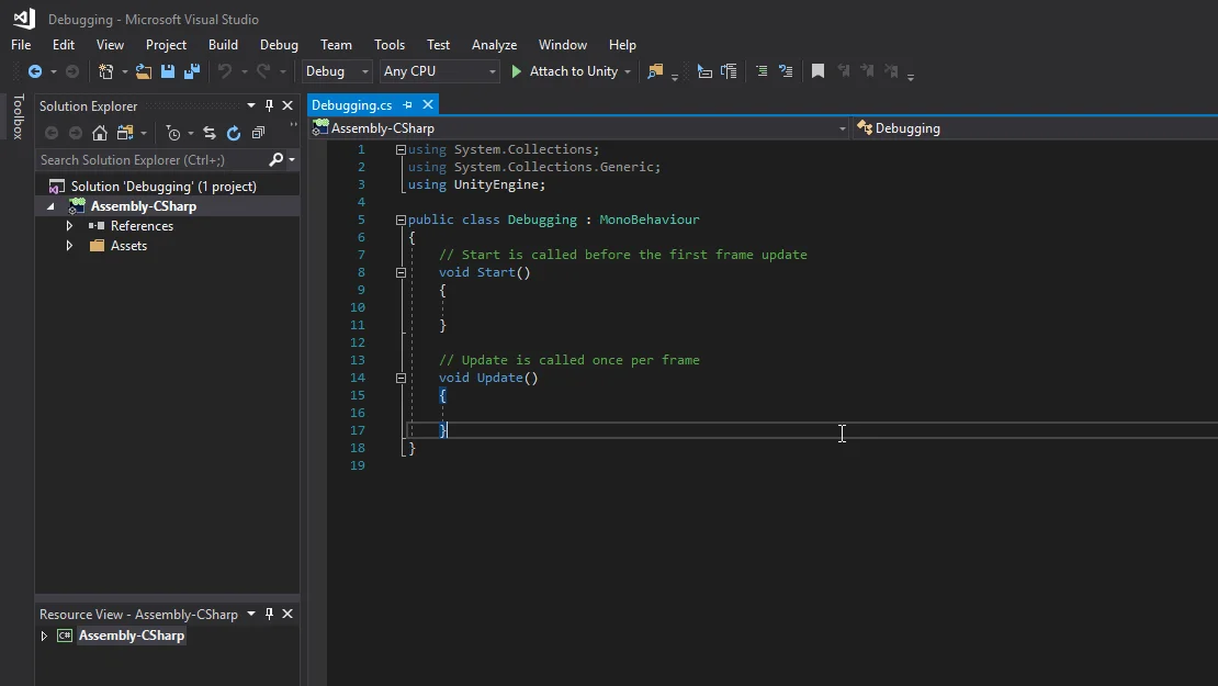
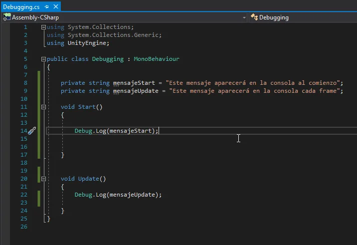
When opening the Script (figure 10) we see that there is some code that is written by default. The basic libraries are imported and we have the Start and Update methods which run automatically.
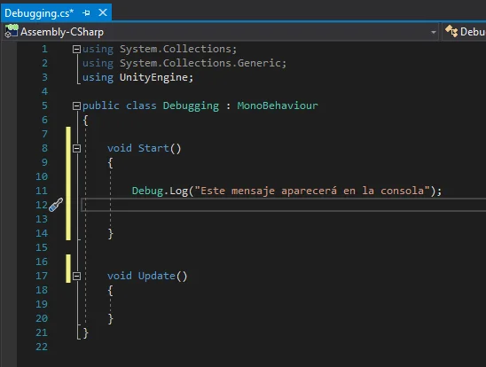
We are going to write an instruction in the Start method. This instruction is the execution of the Log method of the Debug class, to which we will pass the message to print.
As can be seen in figure 11, the instruction is:
Debug.Log(“Este mensaje aparecerá en la consola”);
Which means: “This message will appear in console”.
Fig. 11: We write the Debug.Log instruction in the Start method.
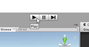
We enter the game mode to test the Script, for this we use the Play button of the Editor (figure 12).
Fig. 12: Button to enter the game mode.Fig. 13: In the lower left corner of the program the console messages also appear.
You can see that the message appears in the lower left corner of the program without having the console open.
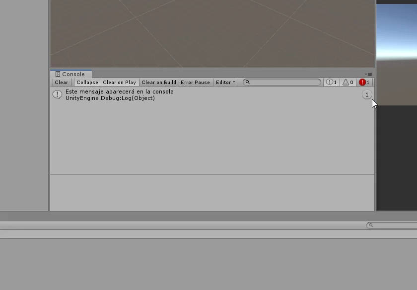
In figure 14 I separated the console window to better visualize the information.
Fig. 14: Message in console, on the right appears a number indicating the number of times the message is sent.
Let’s see what happens if we put a message in the Update method.
Fig. 15: Another message is placed in the Update method.
To the right of the message is a number indicating the number of times the message is printed.
As can be seen in figure 16, the message of the Update method has been printed 82 at the time of capture while in figure 17 the message has been printed 350 times.
Fig. 16: Capturing messages in the first seconds of the game.
Fig. 17: Capturing the messages a few moments later.
Using Variables
The messages that we want to print in console can be stored in variables and the result is the same.
Fig. 18: Two strings are defined with the messages and placed in the methods.
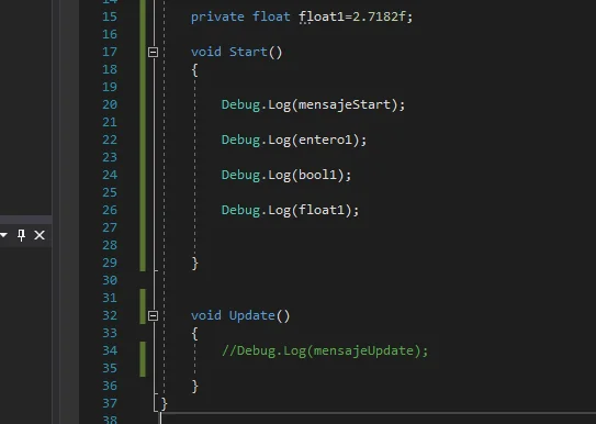
Let’s create some more variables, an integer, a boolean and a float. These three types of variables together with the String are the basic types of variables that we are going to use in any project.
Fig. 19: A variable is defined as integer, bool and float, each with values.
As can be seen in figure 19, we are going to declare them and initialize them with a value. We can do this in different points of the Script, but we will do it at the beginning of the class, before the Start method.
Then we are going to execute three Debug.Log methods passing as parameter the variables.
Fig. 20: Debug.Log is executed with the new variables.
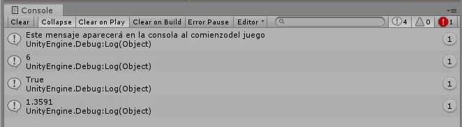
When you enter game mode, all four messages appear on the console.
Fig. 21: The console displays the value of each variable.
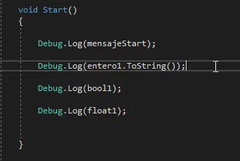
In previous versions it was necessary to execute the ToString() method in order to print the value of a variable that is not a string, as shown in figure 22, this can be done but is no longer necessary, you can pass the variables directly.
Fig. 22: Execution of ToString() that converts the value of the variable into text.
We are going to define 4 new variables, one of each type and give it different values, as shown in figure 23.
Fig. 23: More variables are defined to perform operations.
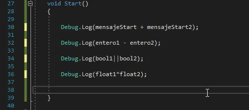
We can make the console print the result of operations with variables, as shown in figure 24.
If we compare the values in figure 23 with the console prints seen in figure 25, we can verify this.
Fig. 24: Operations are entered in the parameter of the Debug.Log methods.Fig. 25: The results of these operations are printed on the console.
It is also possible to concatenate different types of variables and print a message.
Fig. 26: Different types of variable can be concatenated to form the message.
Fig. 27: Message made up of different types of variables.
Frame Counter
Previously we placed a Debug.Log instruction in the Update method, which contained a fixed message.
We are going to print a message that is going to change frame to frame.
Fig. 28: An integer is defined to count the number of frames that pass.
To start with we define an integer to count the frames and initialize it in the value 0.
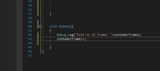
Let’s concatenate the message “This is the frame: ” (including the final space), with the counter value.
After displaying the message in console, we increase the counter so that in the next frame it indicates the next frame number.
These two instructions are shown in Figure 29.
Fig. 29: A message is printed with the frames count and then the counter is increased.
Figures 30 and 31 show the execution of this code at two different times.
Fig. 30: Messages in the first seconds of execution.
Fig. 31: Messages appearing moments later.
Elements of an Array or Integer Vector
Now we are going to apply the Debug.Log Method to analyze the elements of an Array.
An Array is an ordered structure of data of some kind upon which operations can be made. This data structure is like the mathematical vector.
First we are going to declare an Array of integers, this is similar to declaring an integer only by adding the square brackets after the type, as seen in Figure 32.
At the same point we are going to create the Array with the values seen in figure 32.
Fig. 32: A vector of integers with different values is defined.
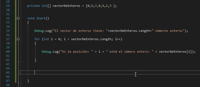
We are going to read the Array in the Start method, first we are going to write a message indicating the size of the vector.
To go through the Array we use a “for” loop that starts from 0 to the amount of Array elements minus one.
Inside the for loop we are going to print a message in console using Debug.Log and concatenating text with the values of the variable.
Fig. 33: In the Start method we are going to analyze the array using Debug.Log.
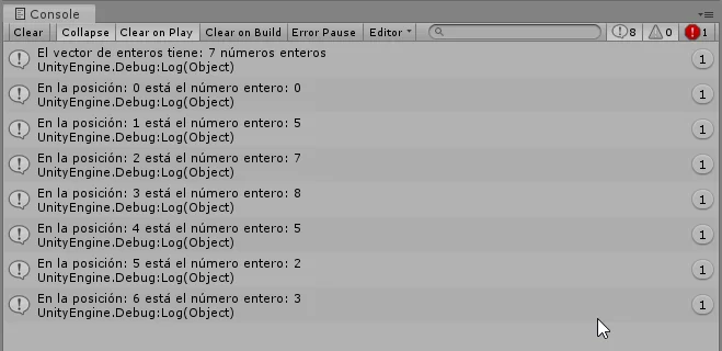
In this way using the console we can study the array and its elements, as can be seen in figure 34.
Fig. 34: Console messages that give us information about the Array.
Print the result of the execution of a Method
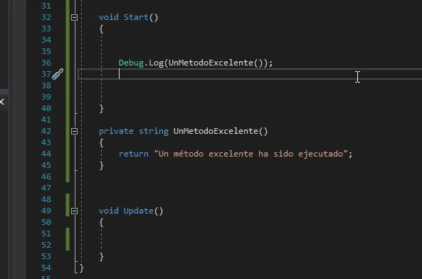
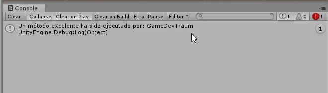
If we have a method that returns a variable, we can apply it as a parameter of the Debug.Log method, as shown in figure 35.
The method “UnMetodoExcelente” is defined which returns a string.
The execution of this code is shown in figure 36.
Fig. 35: A method is defined that returns a string to print message in console.
Fig. 36: The message consists of the string returned by the method.
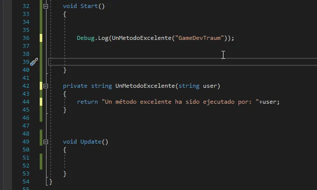
The same could be done with a method that requires parameters, as shown in figure 37.
Fig. 37: A parameter is added to the method.
Fig. 38: The message depends on the parameter we give to the method.
Debug.Log to analyze the result of an if statement
The flow of our program can move in different ways depending on the data, for example in a sentence if, the flow of the program will take one of two possible paths depending on the Boolean variable being evaluated.
In figure 39 we define the if sentence, which will execute one method or the other. Each method prints its characteristic message.
Fig. 39: Two methods are defined, one of which will be called randomly.
In figures 40 and 41 we see the execution in two different moments of the game.
Fig. 40: In this case the BadPath method was executed.
Fig. 41: In this case the “GoodPath” method was executed.
Conclusion
The Debug.Log method is used to write messages in the console.
By strategically placing these messages in our code we are able to visualize the flow of the program, get information about the state of our variables and objects.
The Debug.Log method takes as parameter a variable that can be in principle string, bool, int or float, the basic types of variables that we have analyzed in other articles.
These parameters can be delivered in different ways, for example it is possible to create a message concatenating variables, as the result of a method, enter the variables directly or enter the operations whose results we want to be printed.
Introduction
In this article we are going to see what a script is in programming, we are going to write a simple script in the notepad that does a certain task and give several examples of application.
Script in programming
In simple terms a programming script is a text document where we place instructions or commands that will then be executed by an intelligent device.
These instructions will be written in some programming language in which their syntax must be respected so that each instruction can be translated into machine language. In addition, each script will be a file with a format that will depend on the language in which it is written.
All the scripts of our program make up the source code.
Let’s write a Script right now!
The field of application of programming is very wide, we can write programs for a number of purposes. I invite you to perform the following experiment for the Windows platform:
Let’s open Notepad, that application that has always been in Windows.
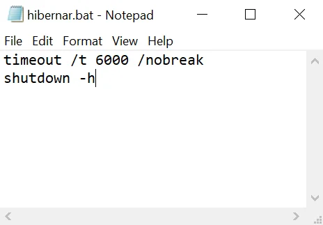
Let’s write the following two lines:
timeout /t 6000 /nobreak
shutdown -h
It should look like this:
Fig. 1: Script made in Notepad. When running, the computer waits 6000 seconds and then goes into hibernation.
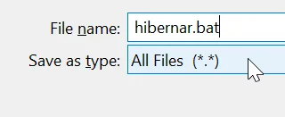
We click on “file-save file as” and make sure to choose the option “All Files (.)”, as shown in Figure 2. We give it a name and end it with the extension “.bat” which is the Batch extension or batches. Let’s save it on the desktop to find it quickly.
Fig. 2: Save How window of Notepad. Put the extension “.bat”.
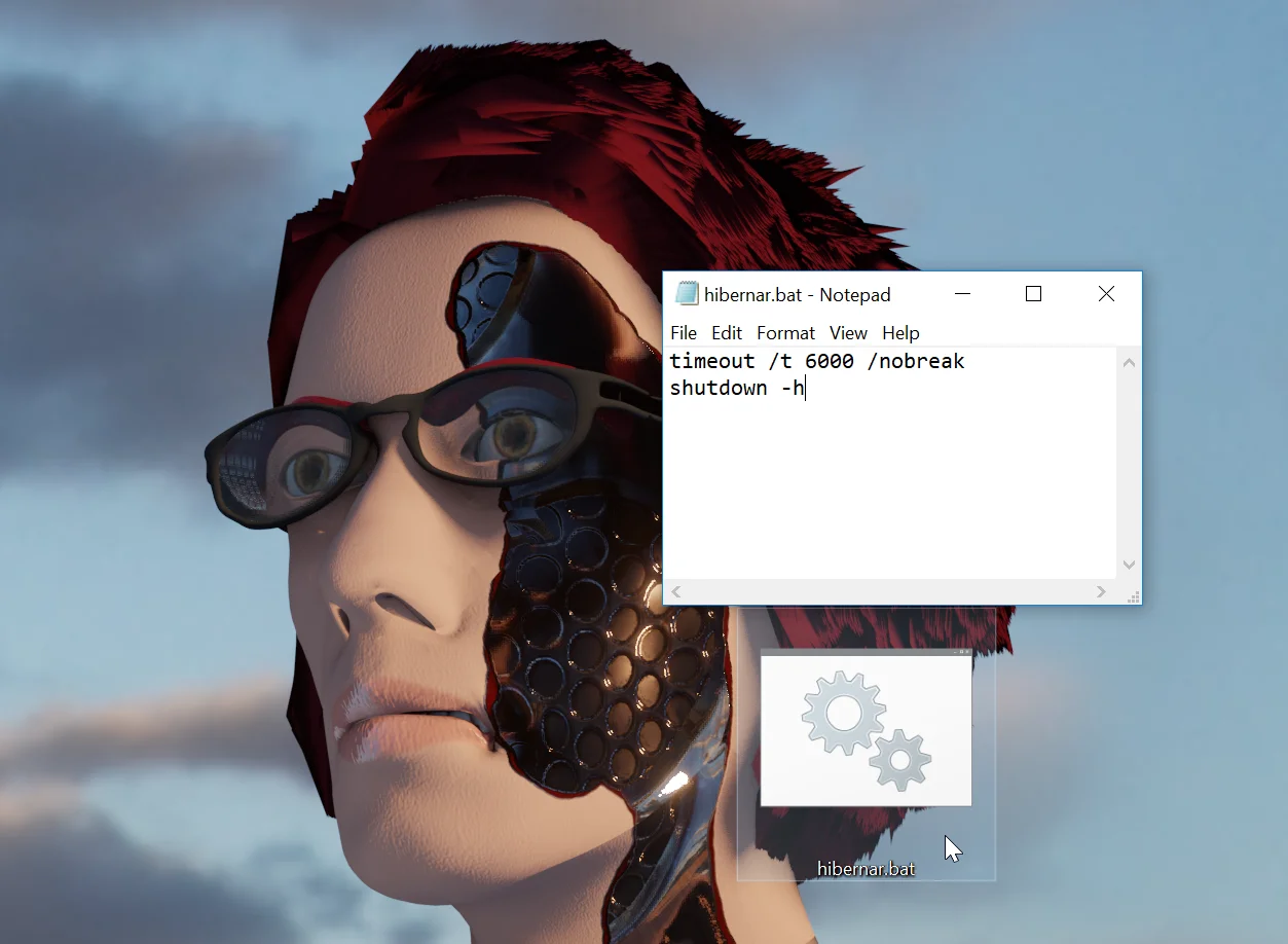
We are generated a Batch file that we can execute by double clicking, figure 3.
Fig. 3: File generated when saving with the extension.
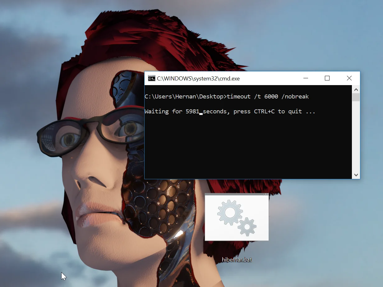
When executing it, the windows terminal opens indicating that it is waiting for a certain amount of time that we have indicated in our Script.
Fig. 4: Execution of the “hibernar.bat” script.
When the 6000 seconds indicated in the script are reached, the second instruction will be executed: “shutdown /h” that will put our equipment in hibernation state.
That’s how easy it is to write a script that fulfills a certain function!
This script is very useful to me to put the computer to hibernate automatically after a certain time, avoiding that it remains on all night.
Other examples of Scripts
Next I’m going to show a series of examples of Scripts that we can find when starting a project that involves programming.
Games made with Unity
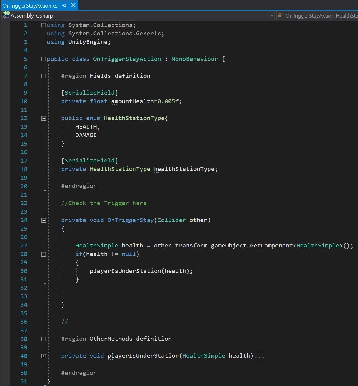
If we want to develop a game in Unity, we are going to find the Scripts in C# language. If we want we can write these scripts in Notepad as long as we save them with the extension “.cs”, but that would be unnecessarily complicated. We have Editors that allow us to check the syntax, auto complete and make the job easier.
Fig. 5: Script in c# belonging to the development of the series “Fundamentals of Unity”.
If you’re interested in learning how to make games at Unity, I invite you to watch the My First Game series at Unity and the new Unity Fundamentals series I’m currently working on. There are videos, articles and files to download.
Android Applications
Maybe you are interested in making an App for Android, in that case an option is to use the Android Studio software.
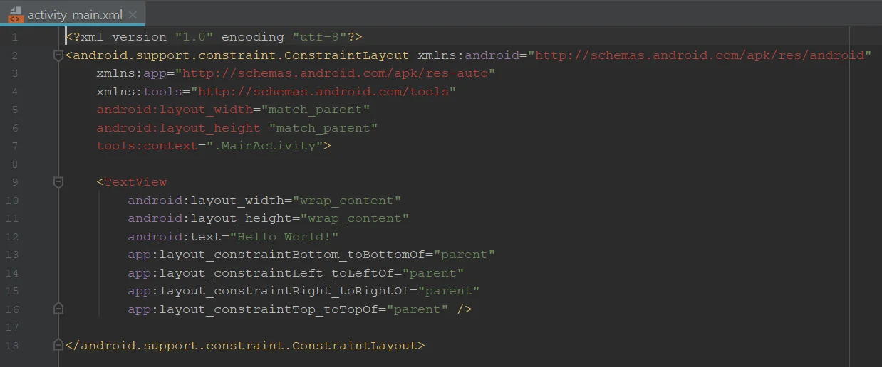
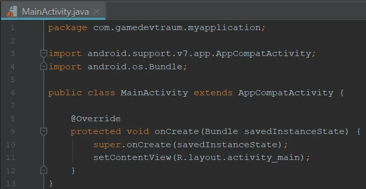
XML Scripts are used to define the design of our application and logic using Java Scripts. Figures 6 and 7 respectively.
Fig. 6: XML script for the design of an application in Android Studio.Fig. 7: Java script for the design of an application in Android Studio.
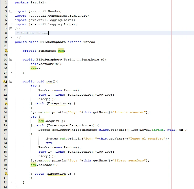
To study programming I have used development environments such as Eclipse or NetBeans, in which I have written Scripts in Java that I could then simulate in the console and analyze the results. Here is an example of a Java script using the NetBeans IDE:
Integrated Development Environments (IDE)
Fig. 8: Java script using NetBeans IDE. The Script is for the study of concurrent programming.
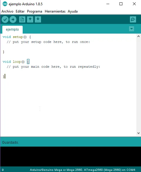
Arduino Projects
Maybe we’re interested in electronics and want to program an Arduino. In that case we are going to write scripts in “.ino” format using the Arduino IDE.
Fig. 9: Arduino default script.
Speaking of Arduino, I leave a video that I uploaded to my channel some time ago about a project in which I used Arduino Mega and sent the information to a simulation made in Unity. The models are made in Unity. I think it would be nice to make a series of videos with a project to combine electronics and game development, just for fun.
Simulación de proceso industrial hecha en Unity 🟢
Other examples can be Scripts for MatLab or SciLab, plugins for Blender, Scripts to process data in Excel tables, scripts to run macros and many other examples.
Conclusion
Scripts in programming are sets of instructions written in some language and that later will be executed by an intelligent device, be it a computer, a mobile phone, and so on.
The field of application of programming is very wide. Depending on what we want to do we will have different tools to write Scripts and these will be in different formats.
Introduction
In this article we are going to see how the OnTriggerExit method works in Unity. This function will allow us to know when the Collider of a certain GameObject, that was previously inside another Collider, has exit.
OnTriggerEnter and OnTriggerExit are very similar methods but it changes the moment in which the execution of these methods happens, knowing exactly these moments will allow us to build solutions.
The following video has summarized information about the OnTrigger events, how to setup the components and how to define the events in a script.
OnTriggerExit Method in Unity
The OnTriggerExit method is defined in the MonoBehaviour class. That is to say that any new Script by default will have it by inheritance.
Several conditions must be met for OnTriggerExit to run.
The first is that there must be two GameObjects with Colliders involved, one of the Colliders must be in Trigger mode, for this you must check the box “Is Trigger” in the inspector.
In addition, at least one of the GameObjects involved must be assigned a RigidBody component, because OnTriggerEnter is related to the physical part of the engine.
Declare OnTriggerExit
The fact that it is defined in the MonoBehaviour class and a new default Script does not mean that we will automatically have OnTriggerExit in our Script, we must declare it and we do it in the following way:
private void OnTriggerExit(Collider c){

//Acciones a realizar cuando se detecta una entrada al Trigger.

}
If the conditions are met, this method will run automatically, so inside we write everything that needs to be done when that happens.
The parameter “Collider c” that receives the method, is the Collider of the GameObject that came into contact with the Trigger. We can use this parameter to do many things, for example get the GameObject that has assigned that collider, we do this simply with:
c.gameObject
From there we can read any other component assigned to GameObject, its tag, its layer, modify what we need and we are allowed to modify, execute methods defined in Scripts that may be assigned and many more actions.
To learn more about programming functions with parameters I invite you to read this article.
Conclusion
The OnTriggerExit method allows us to detect when a GameObject ceases to be in contact with a Collider in Trigger mode and we can execute the desired actions when that happens.
OnTriggerEnter runs automatically, for this to happen there must be some conditions, the first is that there must be two GameObjects with Colliders involved and one of them in Trigger mode and the second is that at least one of the GameObjects must have a RigidBody component assigned.
Introduction
In this article we are going to see how the OnTriggerEnter method works in Unity. This function will allow us to know when the Collider of a certain GameObject has enter another Collider that is specially configured to be able to detect.
OnTriggerEnter and OnTriggerExit are very similar methods but it changes the moment in which the execution of these methods happens, knowing exactly these moments will allow us to build solutions.
The following video has summarized information about the OnTrigger events, how to setup the components and how to define the events in a script.
OnTriggerEnter Method in Unity
The OnTriggerEnter method is defined in the MonoBehaviour class. That is to say that any new Script by default will have it by inheritance.
Several conditions must be met for OnTriggerEnter to run.
The first is that there must be two GameObjects with Colliders involved, one of the Colliders must be in Trigger mode, for this you must check the box “Is Trigger” in the inspector.
In addition, at least one of the GameObjects involved must be assigned a RigidBody component, because OnTriggerEnter is related to the physical part of the engine.
Declare OnTriggerEnter
The fact that it is defined in the MonoBehaviour class and a new default Script does not mean that we will automatically have OnTriggerEnter in our Script, we must declare it and we do it in the following way:
private void OnTriggerEnter(Collider c){

//Acciones a realizar cuando se detecta una entrada al Trigger.

}
If the conditions are met, this method will run automatically, so inside we write everything that needs to be done when that happens.
The parameter “Collider c” that receives the method, is the Collider of the GameObject that came into contact with the Trigger. We can use this parameter to do many things, for example get the GameObject that has assigned that collider, we do this simply with:
c.gameObject
From there we can read any other component assigned to GameObject, its tag, its layer, modify what we need and we are allowed to modify, execute methods defined in Scripts that may be assigned and many more actions.
To learn more about programming functions with parameters I invite you to read this article.
Conclusion
The OnTriggerEnter method allows us to detect when two GameObjects overlap their Colliders, so we can apply all the necessary actions.
OnTriggerEnter runs automatically, for this to happen there must be some conditions, the first is that there must be two GameObjects with Colliders involved and one of them in Trigger mode and the second is that at least one of the GameObjects must have a RigidBody component assigned.
This website uses cookies to improve your experience. We'll assume you're ok with this, but you can opt-out if you wish. Cookie settingsACCEPT
Privacy & Cookies Policy
Privacy Overview
This website uses cookies to improve your experience while you navigate through the website. Out of these cookies, the cookies that are categorized as necessary are stored on your browser as they are as essential for the working of basic functionalities of the website. We also use third-party cookies that help us analyze and understand how you use this website. These cookies will be stored in your browser only with your consent. You also have the option to opt-out of these cookies. But opting out of some of these cookies may have an effect on your browsing experience.
Necessary cookies are absolutely essential for the website to function properly. This category only includes cookies that ensures basic functionalities and security features of the website. These cookies do not store any personal information.


![\begin{equation*} t \in [0,2π ] \end{equation*}](https://gamedevtraum.com/wp-content/ql-cache/quicklatex.com-f4cd992e0487b554030c2dbeabc2b640_l3.png "Rendered by QuickLaTeX.com")


![\[ \boxed{n = (-1)^s . 2^{(e-127)} . (1+m)}\]](https://gamedevtraum.com/wp-content/ql-cache/quicklatex.com-08e314f4df9a84a2bbbb8f3c4f3c56f5_l3.png "Rendered by QuickLaTeX.com")
![🎥[ BLENDER TIMELAPSE ] Cubo de Rubik 3x3x3 en Blender](https://i.ytimg.com/vi/u0kyAugbqiY/hqdefault.jpg)
![🎥[BLENDER TIMELAPSE] Peones de Ajedrez (2 formas de modelarlos en 3D)](https://i.ytimg.com/vi/4KtRTcn1o0s/hqdefault.jpg)


![Sistema Lockpick de Skyrim en Blender 2.8, texturas con Substance Painter [Timelapse]](https://i.ytimg.com/vi/09s2VS5TFEI/hqdefault.jpg)