Introduction
In this article we see what MODULARIZATION is in programming and why it is important. We will also see examples of applications in C# language in Unity.
What is MODULARIZATION in Programming and what is it for?
The word modularization comes from module, whose textual definition is: ” each of a set of standardized parts or independent units that can be used to construct a more complex structure, such as an item of furniture or a building”.
Modularization is the process by which we select and group programming instructions that fulfill a specific function.
Creating modules is important because of the following:
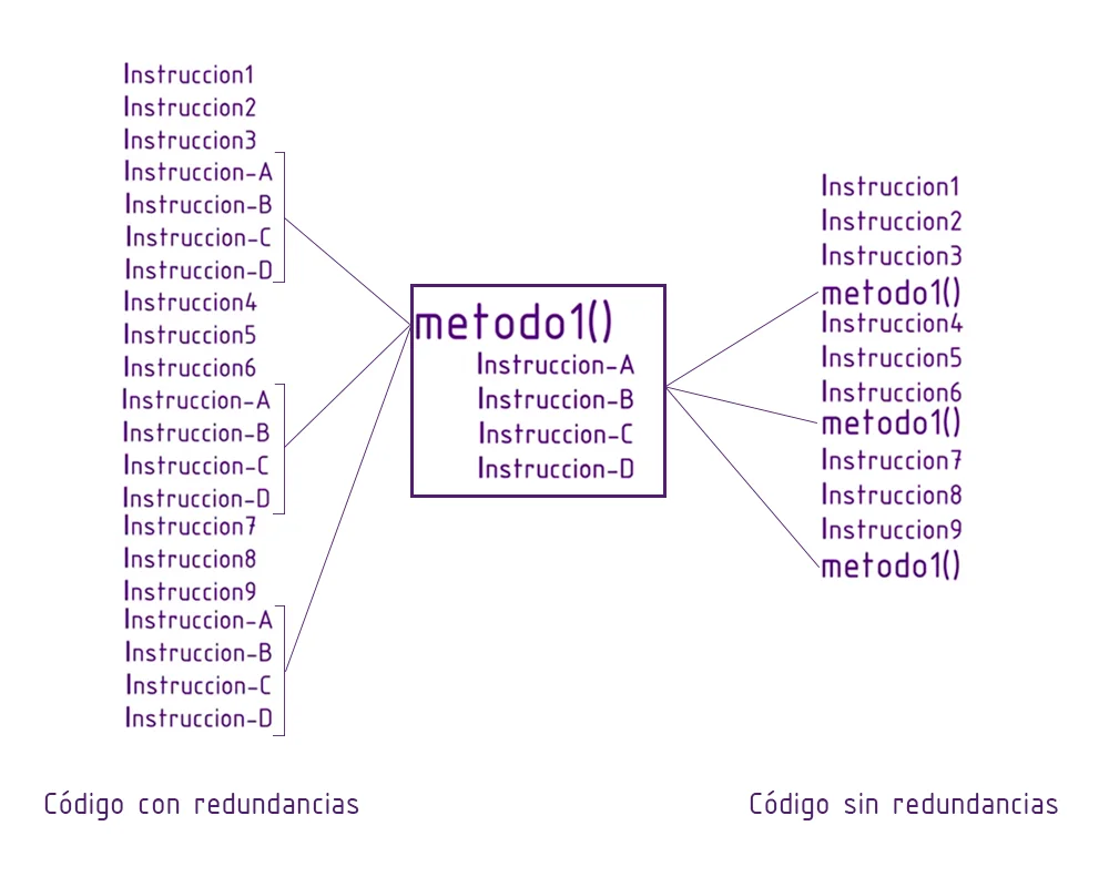
Suppose we have a problem, as complex as you want, and the solution is to execute as many programming instructions as you need. Using programming modules, we can build a solution that can be executed using only one instruction. This instruction will go to the content of the module, execute each of its instructions and when the program ends, it will return to the point where the module was called.
The advantage of this is that we create the module only once and then we can reuse it as many times as necessary and from any part of the code, in addition, we no longer need to think about the internal functioning of the module, we use it as a whole that we know will perform a certain function. In other words, we increase the degree of abstraction of our code.

Characteristics of the modules in programming
Regarding Functionality
A module should have a specific function and not go beyond its responsibilities. For example, if we have a module that calculates the product of two numbers and returns the result, it would not be appropriate for it to also print messages on the screen or do anything else that goes beyond its purpose.
Regarding Identification
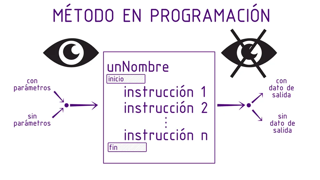
The modules have an identification name that allows us to execute them, it is recommended that we choose this name so that it is as representative as possible of the function it performs, that way it is more intuitive when using it.
Input parameters
The modules can accept input data that will be used by your internal instructions to perform the function.
When defining a module, you should indicate all the parameters it requires and what kind of data it is. At the moment of executing the module, all the necessary parameters should be added, in the established order and they should be of the right type.
Output parameter
The modules can return a data as a result of its execution.
When defining a method, the type of data it returns must be indicated and the last instruction of the module must be the return of that data. When the module is executed, it must be taken into account that the call to that method implies a data as a result, so we must see what is done with that data, we can, for example, assign it to a variable or an object.
Visibility
When we define a module we can give it different types of visibility that will limit the access to them, for example the modules that belong to the internal functioning of a programming class are usually defined as private, so they cannot be accessed from a context external to that class.
In C# we have three types of visibility, public, private and protected.
Public visibility implies that the function can be accessed from any context, i.e. we can for example execute the function from another programming script.
Private visibility implies in simple terms that the module can only be accessed from the programming script itself.
Protected visibility is used when we have class inheritance and serves to allow subclasses to access these modules, but not external classes.

Definition of a programming module in C#
To create a module in C# we are going to use the declaration syntax of a programming method, which consists in first indicating the visibility type, then the return data type (or write “void” if it does not return data), then the module identification name (it is recommended to start with capital letters and use camel case), then between parentheses all the data required by the method including the data type and finally the keys are opened and closed. All the instructions of the module will be inside those keys.
In figure 3 we can see the syntax of several generic modules, all of them with public visibility (to make it private we must use the word “private”).
On the top left we have a module that does not return data (void is used in the definition) and neither requires input parameters (it opens and closes parenthesis).
At the top right we have a method that does not return data and requires a number N of parameters (we see that in brackets are included the data separated by comma). The parameter p1 could be for example “bool b1” indicating that it is a bool type and its name is “b1”. So, inside the module we can use b1 knowing that it is the information that comes from the outside.

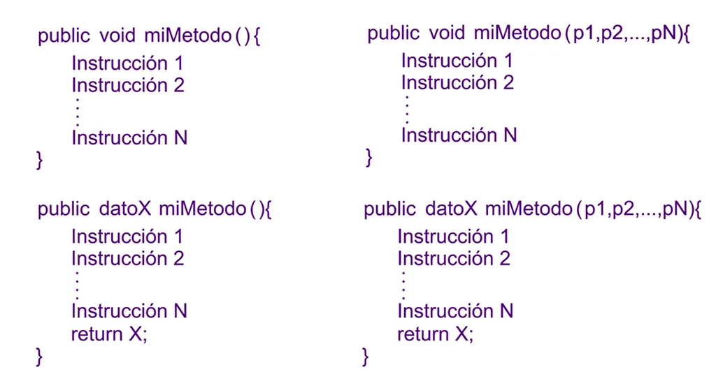
In figure 3, at the bottom left we have a method that doesn’t require input parameters but does return a data, since next to public it says “datoX”. Instead of datoX we have to put a data type, like a primitive variable or an object, for example “int” indicates that the module returns an integer value, while “Vector3” indicates that the module is going to return an object of the Vector3 class. Note that at the end of the method a value of name X is returned, this value must be of the same type that was declared in the method.
In figure 3, at the bottom right we have a method that requires parameters and returns a data.
Example of a module in C#: Calculating the area of a circle with a certain radius
We are going to design a module that is in charge of calculating the area of a circle. This module will receive as parameter a real value that represents the radius of the circle and will return a real value that will be the value of the area of a circle with that radius.
Pseudocode
Function AreaOfCircleWithRadius (FLOAT radius)
– BEGIN
– – Float area <- PI * radius * radius
– – RETURN area
– END
Implementation with C#
The syntax in C# language of a method based on the above pseudocode is as follows.
Module Definition
private float AreaOfCircleWithRadius(float radius){
      float area = Mathf.PI * radius * radius;
      return area;
}
Of course this is not the only option, you can also do:
private float AreaOfCircleWithRadius(float radius){
      return Mathf.PI * radius * radius;
}
Calling the module
Then we can for example make use of this programming module from Unity’s Start method in the following way:
void Start(){
      float r = 5;
      float a=AreaOfCircleWithRadius(r);
      Debug.Log("The area of a circle with radius: "+r+" is: "+a+".");
}


![\[\binom{n}{m} = \frac{n!}{m!(n-m)!}\]](https://gamedevtraum.com/wp-content/ql-cache/quicklatex.com-3dd201ecfcc4341982584f3674602e5f_l3.png "Rendered by QuickLaTeX.com")