In this article we will see how to execute functions defined in one script from a second script. First we look at the generic procedure.
In the following video I explain how to call functions from another script. All the information is presented to you as a generic example, two scripts, “ScriptA” and “ScriptB“, the function we want to call is defined inside ScriptA, so from ScriptB we are going to access to ScriptA.
1. We start with 2 Scripts, “ScriptA” and “ScriptB”. In Script A is the function we want to call. In Script B we are going to call the function that is in ScriptA.
2. In ScriptA we make sure that the function is declared as public, otherwise we will not be able to access it from a context outside of ScriptA.
3. In ScriptB we declare a ScriptA type variable and we must find the reference of that object. This will depend on where we are programming, in the case of Unity we will do it in the Start method and with the instruction FindObjectOfType.
4. To call the function of ScriptA from ScriptB, we use the rererence we defined from A and with the dot operator we can access it and execute it inside ScriptB.
Introduction
In this article we will see how to tell if an integer is odd or even using programming. We solve the algorithm in C# language for Unity.
An even number is a number that is a multiple of 2, that is we can express that number as 2 multiplied by another number and the whole expression will be equivalent. An odd number is a number that is not a multiple of 2.
It can also be said that an even number is divisible by 2, meaning that when you divide the number by 2 the remainder of the division is 0, whereas division between an odd number and 2 will always have remainder 1. We can use this fact to create an algorithm that checks whether a number is odd or even.
Prepare the scene for testing
To test the code to verify if an integer is odd or even we’ll create a script with any name, in my case I used “EvenOrOdd”, then we create an empty GameObject in the hierarchy (figure 1) and assign that script in the inspector (figure 2), that way when we enter the game mode the script will run and we can test the code.
Fig. 1: Creating an Empty GameObject in the hierarchy in Unity
Fig. 2: Assigning the script to the GameObject
Module Operator
The module operator allows us to know how much the rest is worth when making a division.
Let’s consider a division operation between two integers, for example 5 divided by 3, the integer result of this division is 1 and the rest of the division is 2, we can see that: 3 x 1 + 2 = 5.
Then, taking into account what we said in the introduction about even numbers and divisibility by 2, if we apply the operation module 2 to any number and the result is equal to 0, we can say that the number is divisible by 2 and consequently is an even number. If the result is not 0, then the number is odd.
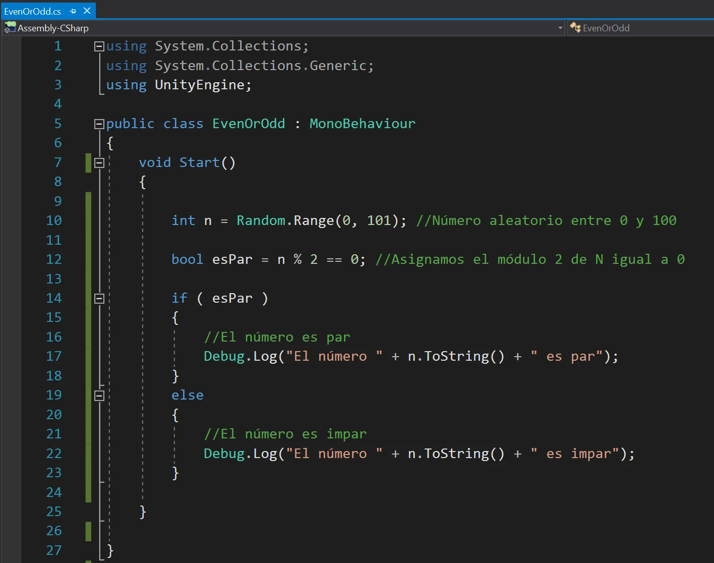
The programming of this algorithm can be seen below in figure 3, in line 10 a random number between 0 and 100 is generated, then in line 12 we make this check if the module 2 of that number is equal to 0 and we assign that logical result to the logic variable “esPar”. Finally, using the if statement, we check if the condition is true or false and print a message according to each case.
Fig. 3: Algorithm to know if an integer is odd or even in C#, Unity.
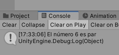
When entering the game mode, the code defined in the Start method is executed, in figures 4 and 5 you can see two different executions of this algorithm, one for an even number and another for an odd number.
Fig. 4: Console message indicating that the generated number is even.
Fig. 5: Console message indicating that the generated number is odd.
Introduction
In this article we analyze an experiment to understand what are the differences between Update and FixedUpdate in Unity. To see these differences I set up a simple Unity scene with two cubes and some programming scripts, you will find the Unity Packge for download in this article.
To begin with, the Update and FixedUpdate methods are functions that belong to the MonoBehaviour class and will be executed automatically and cyclically when we place those Scripts in the hierarchy.
Summary of the differences between Update and FixedUpdate in Unity
1. The amount of Update executions per second is variable, while the amount of FixedUpdate executions per second is fixed.
2. In general, you have no control over the execution of the update method, it will depend on the performance of the computer in which the game is running. For the FixedUpdate function we can change the Fixed Time Step, by default is 0.02 seconds (20 milliseconds), so we know exactly how many times this function is executed.
3. Both functions are used to make changes in time, from the above it can be concluded that the Update method is more convenient for the logical part and FixedUpdate for the physical part, movements and animations, i.e. actions that must change regularly in time.
How to see the differences between Update and FixedUpdate using the package to download
When you import the package you will have a folder that contains all the necessary files, what you have to do is open the scene that is inside the folder, called “UpdateFixedUpdate”.
Inside the scene we have a frame per second counter to know the refresh rate of the game at all times.
We have two Cubes called Update and FixedUpdate, both have assigned a script called “UpdateFixedUpdate” in which is defined a speed for the cube movement and a logical variable that will determine if the cube movement is done in the Update function or in the FixedUpdate function.
Then there is another GameObject called Saturation that has assigned a Script called “CreateObjectsForever”, when this Script is activated it will start instantiating cubes as children of the Saturation GameObject in an uninterrupted way, which will cause little by little a processing overload and with a little analysis it will allow us to understand the differences between Update and FixedUpdate in Unity.
Procedure for Analysis
First Test without Overload
Initially we make sure that the GameObject Saturation is disabled or your “CreateObjectsForever” script is disabled, so that initially no saturation occurs in the game.
We make sure that both objects have the same speed in their Script UpdateFixedUpdate and that in the Update object the box “Use Fixed Update” is unchecked, while in the FixedUpdate object, that box is checked.
We enter the game mode and observe how the cubes behave. In my case we can see that the cube that moves using the Update method moves faster than the cube that moves in the FixedUpdate method. The cube that moves with Update does so at more than twice the speed and sometimes moves faster and sometimes slower, while the other cube moves regularly over time.
Second Test with Overload
Now we activate the Saturation object (or its script), to activate the instantiation of the objects.
When entering the Game Mode, you will notice that the game’s FPS begin to gradually decrease. This change can be even more drastic if we select the Saturation object in the hierarchy and if we are looking at it closely in the Editor tab. But the most important thing that we notice is that the speed of the cube that moves with Update starts to decrease, the more the overload, the slower the cube moves, until in a moment it is overtaken by the cube that moves with FixedUpdate.
This indicates that the higher the processing saturation, the Update function is executed less times per second, while the FixedUpdate function is executed regularly in time and, even though the game starts to have lag, the movements will be proportional.
Introduction
In this article we see how to export a game from Unity to Android and look at some of the problems we may encounter in the process and how to fix them.
In the following link you can see the basic setup to export a Unity project to Android, creating a 32 and 64 bits version that can be uploaded to Google Play, I also show how I solved an annoying error with the message “IL2CPP.exe did not run properly”.
When installing Unity we must make sure we also download the Android package, so if you haven’t done this or don’t remember it, it’s a good opportunity to download the latest version of Unity along with all the necessary packages.
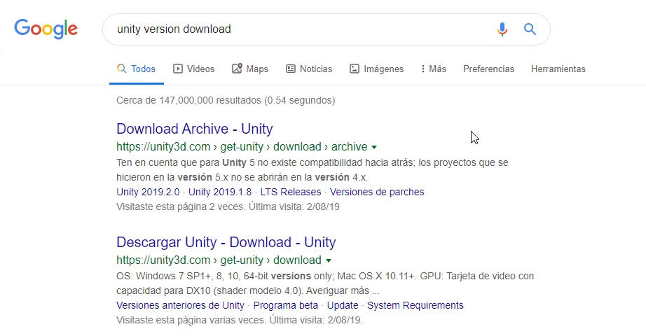
In particular I like to see all available versions, so in Google I usually search with the term “unity version download”, which leads me to the page with all versions (first page in figure 1).
Fig. 1: We look for the page that contains all versions of Unity.
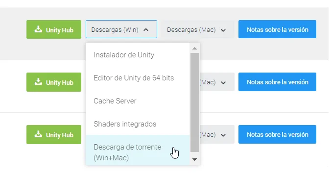
From there we will access a page like the one shown in figure 2, in my case, because my connection is somewhat unstable, I download Unity using torrent.
Fig. 2: In the list we have several options to download Unity.
Fig. 3: In my case I download the latest version by torrent.
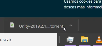
Clicking the highlighted option in Figure 3 automatically downloads a torrent file.
Fig. 4: Downloading the torrent file and open it.
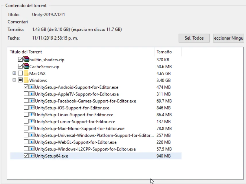
We will need to download the Unity editor and the Android Build Support, in figure 5 are selected the necessary packages.
Fig. 5: In the torrent window we choose the necessary files, in this case we need at least the two selected files.
Configure Android SDK y JDK
To export our Unity games to Android we need to use some external tools, the Android Software Development Kit and the Java Development Kit.
If you don’t have these two kits installed, I’ll show you some screenshots and download links later, for now let’s assume they are installed and move on to the Unity part.
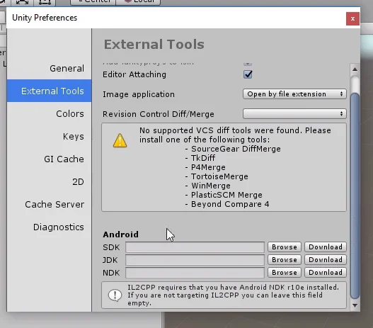
Enter Edit > Preferences and go to the External Tools part, there must be fields to indicate the path of the Android SDK and JDK, as seen at the bottom of figure 6.
Fig. 6: In the preferences window we go to the External Tools part.
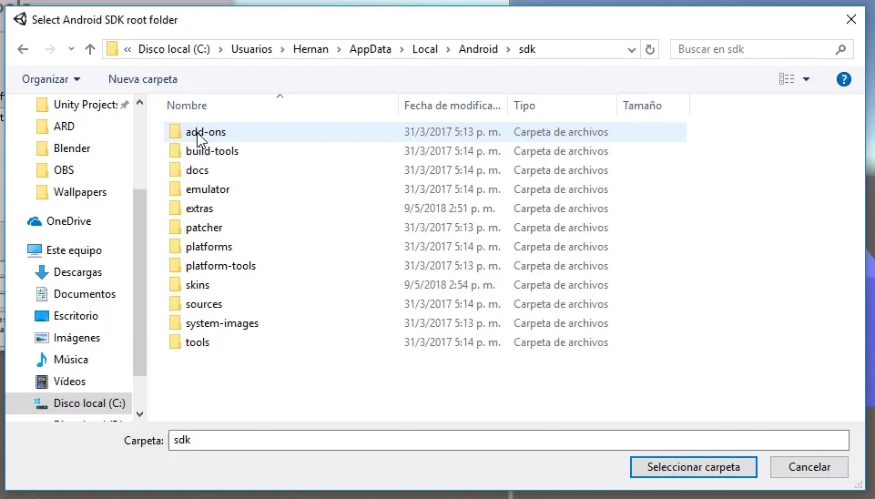
By clicking on Browse, we indicate the path of these two development kits. The default installation path of the Android SDK is shown in figure 7, please note that the AppData folder could be hidden.
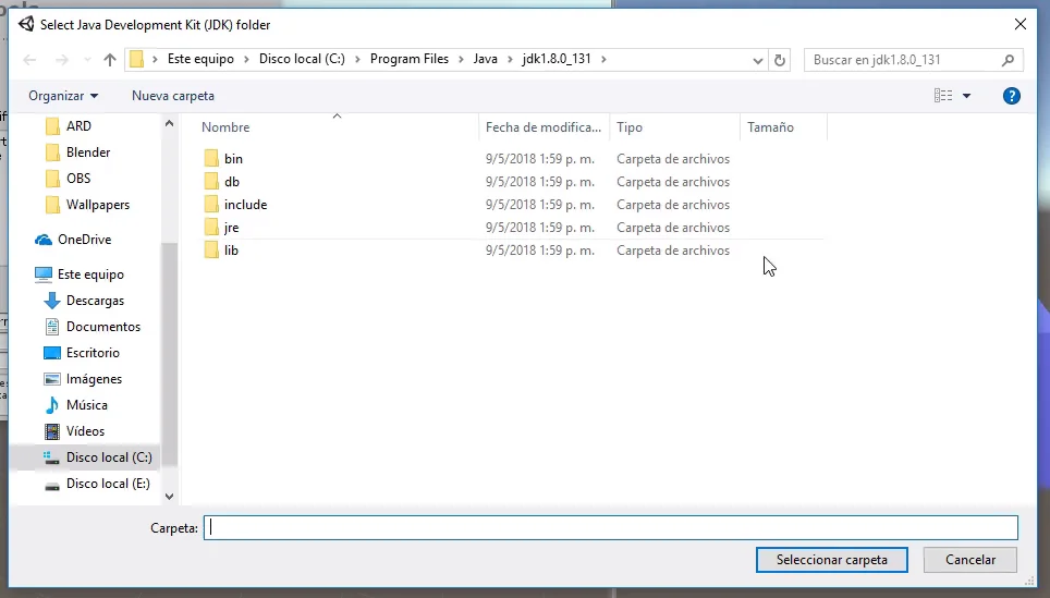
The path of the JDK is shown in Figure 8, inside program files, Java.
Fig. 7: This is the location of the Android SDK, if you do not find this on your disc read below.
Fig. 8: This is the location of the JDK, if you do not find this on your disk read below.
Configure Unity for the Android Platform
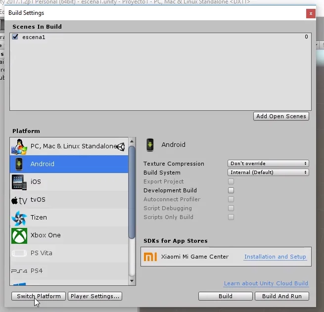
Now we must tell Unity the type of platform we want to export to, in this case Android. To do this, go to File > Build Settings and a window like the one shown in figure 9 will be displayed.
Fig. 9: In the Build Settings tab we select the Android platform and put Switch Platform.
In this window we select the option Android and click on Switch Platform, with this Unity makes a background work and after a moment the project is already adapted to work with Android.
Before creating a compilation we need to set up a few more things.
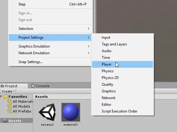
Go to the project’s Player window, in the Edit > Project Settings > Player tab.
Fig. 10: Let’s go to Edit > Project Settings > Player, to make the necessary settings to export from Unity to Android.
Here we can enter our brand, the name of the game, icons, Google Play keys, among other things.
Fig. 11: Here we can put the name of our Studio and the name of the Game.
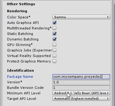
At this time we are interested in creating an APK version of the game to test on an Android device, so let’s go directly to the “Other Settings” part and in the field called “Package Name” we have to indicate an identification name that will have in Android.
This is mostly to differentiate our application from all others in existence. The structure of this name should be like this: “com.Company.ProductName”.
For example if GameDevTraum creates a game called “Maze”, the name of the package could be: com.gamedevtraum.maze. It does not need to match a web domain.
In figure 13 we see that I simply used the name: com.mycompany.proyecto1 and this already allowed me to create an Android build.
Fig. 12: A package name is required in order to compile for Android.
Fig. 13: Example of package name.
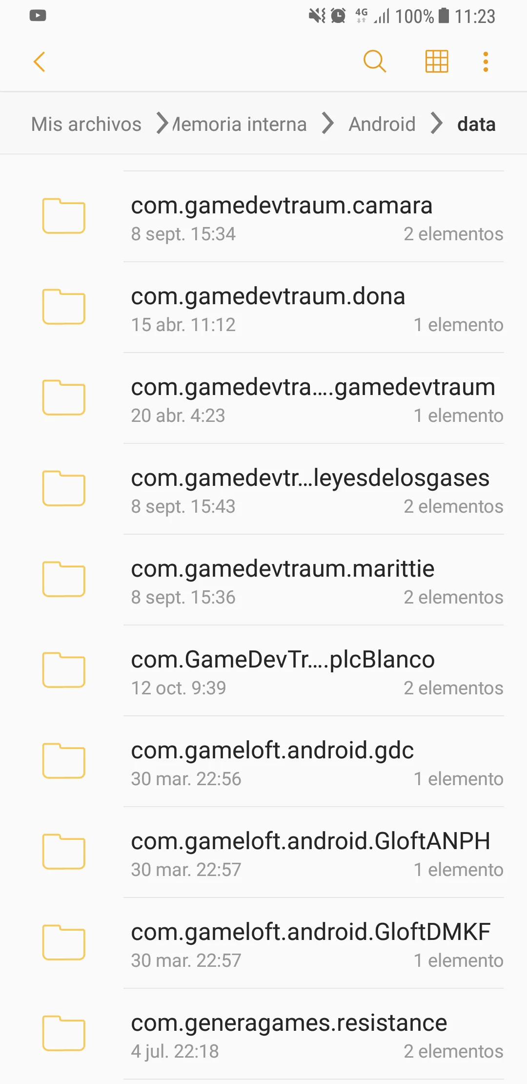
This package name will appear for example in the Android folder of our device.
Fig. 14: The package name is the name of the application installation folder.
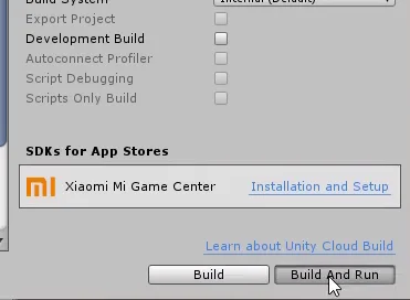
With this we can basically export our game from Unity to Android, go back to the Build Settings window and click on Build and Run.
Fig. 15: With this we are ready to compile, in the Build Settings window we click on Build and Run.
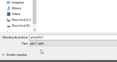
Here we must enter a location and a name for the final file. When you hit Save, the compilation process begins and when it finishes, you have an .apk file that you can install on an API-compatible Android device.
Fig. 16: You will be asked to select a location and a name for the file exported from Unity to Android.
Fig. 17: When the compilation process is finished we will have an .apk file to install in Android.
Unknown sources
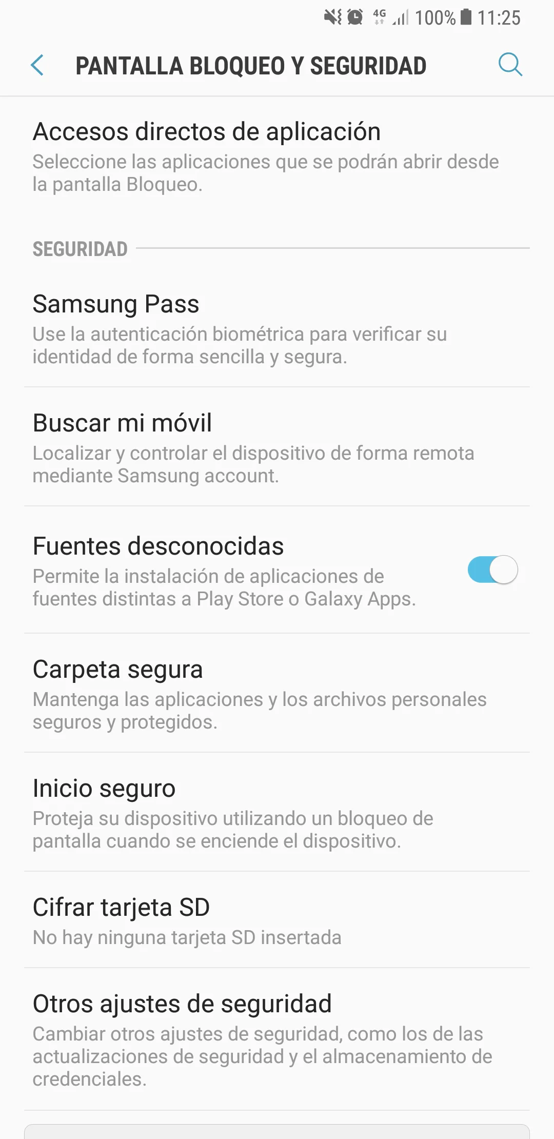
By default Android devices reject applications that come from unknown sources, i.e. that are not signed and approved.
To test our game we must allow this type of application to be installed. We can do it from the Android configuration, in my case from “Screen Lock and Security”. You can also do it from the installer and indicate that it is allowed only for that particular installation, that way we will keep rejecting applications from unknown sources.
Fig. 18: At this point, to install the game in an Android device we must accept the unknown sources, this can be done directly from the installer.
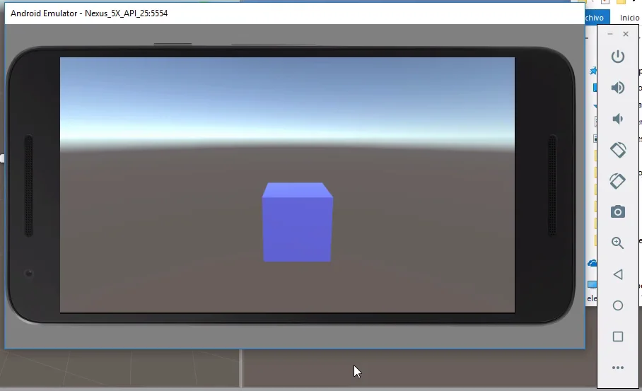
We installed the application on our Android and can now test it. In my case I used directly the Android Studio emulator, as you can see in figure 19.
Fig. 19: Testing the application from the Android Studio emulator
There are two ways to install it, one is to download and install the complete Android Studio program. The other way is to download only the Android SDK, scrolling on the same page you will find the downloads. Figures 20 and 21.
Fig. 20: A quick way to get the Android SDK is to directly install Android Studio.
Fig. 21: The Android SDK can also be downloaded individually.
Java Development Kit (JDK)
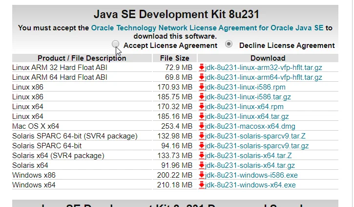
You can download this JDK from the Java Development Kit download page. In figure 22 we see the download page, we must accept the license terms and then choose the appropriate package for our operating system.
Fig. 22: Java Development Kit (JDK) download page
Environment Variables
Some years ago it was necessary to manually add some Environment variables to the operating system in order to create Android applications. I think this is no longer necessary, but anyway if all the above has not worked I leave you some information about these environment variables to guide you and you can find a solution.
In the following video you can see how to check if you already have this environment variable defined and how to define it if not.
ADD Environment Variables to the system 👉
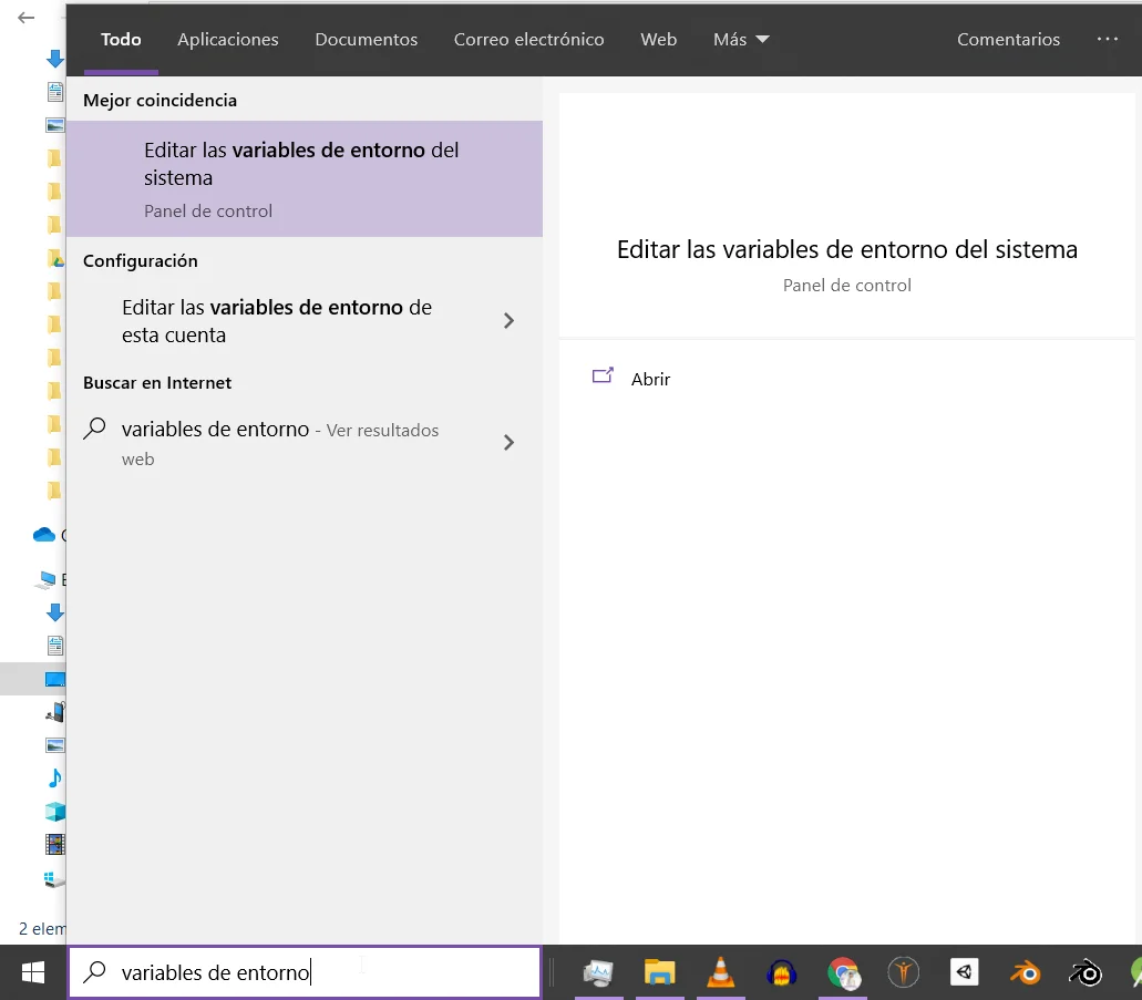
If we write “Environment Variables” in the Windows search bar, the option “Edit system environment variables” appears, as shown in figure 23.
When entering this option, the system properties window appears and there we have a button to view and edit the System Environment Variables.
In my case it was not necessary to add them manually so I will not go further than this, with this base you can search the web for some solution to the particular problem you have.
Fig. 23: Some time ago it was necessary to create some environment variables in order to create Android applications.
Fig. 24: Location of environment variables to be added or modified
Introduction
The objective of this solution is to find a box with the minimum volume that encloses a 3D model in Unity.
The following video is in spanish but you can activate the English subtitles. I explain how to use the solution and what things to take into account when creating the 3D model in order not to have problems in Unity.
Inside the package come two files, a Script called “WrappingCube” that must be assigned to the object we want to wrap with the box. The other file is a predefined transparent material, it can be assigned to the space in the inspector of the WrappingCube component, this material will be assigned automatically to the cube.
How to use the solution
Just add this script to the object you want to wrap with a box, make sure to add it to the one that has the Mesh Renderer Component, if you add this script to an empty GameObject it won’t work.
How the wrapping box is generated
To generate the cube something called “Bounding Box” is used, which is precisely a box that encloses the object, however one detail must be taken into account and that is that this bounding box is axis-oriented, therefore if we rotate the piece, the bounding box will adjust its dimensions of width, length and height until it completely covers the model.
Therefore, for this solution to work, the 3D model must come with the standardized orientation from the 3D modelling software, this means orienting the model in a consistent way according to the global coordinate axes and then applying the rotation to the object.
Introduction
Here is a solution for a First Person Player to activate buttons, switches, levers and more in Unity.
The solution consists of three Scripts that interact with each other to solve the detection of the interactive elements and their activation. In addition, two Scripts are provided as examples to achieve what is observed in the following video on the left:
It is important to mention that in this solution no particular action is solved, although two Scripts are provided that exemplify the use, each particular action must be programmed.
Description of the download files
This solution consists of three basic scripts: “CheckInteraction”, “InteractionReceiver” and “IAction
CheckInteraction is in charge of checking if you are observing something that you can interact with, you can add it to any GameObject but it is coherent to place it in our character.
InteractionReceiver is placed on all objects in our world that the character can operate, for example buttons, levers, doors, etc. The objects assigned to this script must also have a Collider assigned to them so that the Check-Interaction Script can detect them, otherwise you won’t be able to add this Script to the GameObject.
IAction is a programming interface, it is not applied on any GameObject but it is necessary for the solution and we must pay attention to how to use it.
In addition, two more scripts are provided as examples to understand how the solution is used.
Extra: User Interface
The package also includes the simple user interface seen in the video, which allows you to display messages on the screen.
Application Example – Activate Button in Unity
Now let’s see how to use this solution to be able to activate a button in Unity and perform actions with that.
To begin with, we start with a simple scene where there is a button and a gate.
We assign the CheckInteraction Script to this prefab, the field “minInteractionDistance” is the minimum distance the player has to be in order to interact with the object, in my case I put 4.
The “rayOrigin” field is the point from where the ray originates to check the interaction, in this case I place the character’s camera, that way the character will be able to “see” the objects that are in the center of the screen.
Fig. 1: The CheckInteraction Script is assigned to the first-person controller.
Receivers – Buttons or switches
The objects that can be operated (such as buttons, switches, levers, etc.) will be assigned the “ReceiverInteraction” script, this will make the “CheckInteraction” script detect these objects and allow them to be operated with the E key.
We can add a message to the interaction receiver and then do things with this message, for example show it on the screen as seen in the video, for this there is a region marked with comments in the CheckInteraction Script in which a Debug.Log is done showing the message in the console.
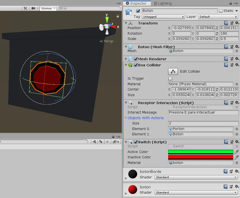
Fig. 2: The InteractionReceiver Script is assigned to the object with which you can interact. This object is also assigned the Script switch of the example.
Objects with action
When we press the button two things will happen, the first is that the gate will open or close depending on its current status, the second action is that the button changes to green when the gate is open and to red when it is closed.
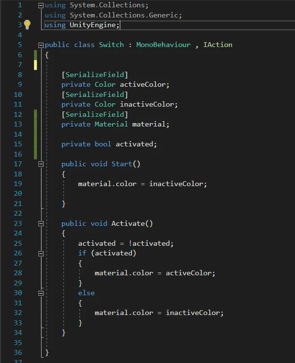
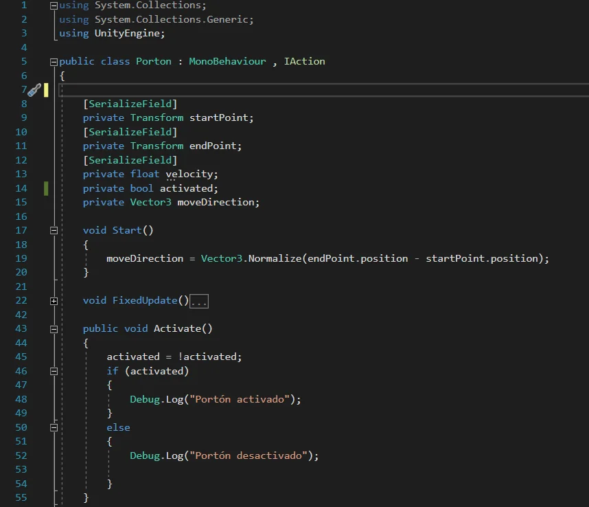
These two actions are programmed individually using two Scripts: “Switch” assigned to the GameObject of the button (figure 2) and Gate (Porton in spanish) assigned to the GameObject of the gate (figure 3).
Fig. 3: The gate is assigned the Gate Script that comes in the downloads as an example.
Scripts that solve the actions
The actions must be specifically programmed, that is, we must create more scripts that solve the action. This will depend on the needs of each one.
In this article we are going to see the two scripts that solve the button and gate actions.
The requirement for action scripts is that they implement “IAction”, a programming interface. This will require our script to have a method called “Activate” defined, within which we will do everything the action needs to do when it is activated by the receiver.
In figures 4 and 5 we see examples for the button and for the gate. I’ll probably make videos explaining how to solve more mechanisms using this basic interaction system and probably we’ll improve it as well.
Fig. 4: The example script “Switch” implements the Iaction interface.
Fig. 5: The example Script “Gate” implements the Iaction interface.
Assigning Actions to the Interaction Receiver
Once we have the actions programmed, we assign them to the corresponding GameObjects and select the object we use as the trigger for those actions (in this case the button).
In the Script InteractionReceiver we have a field called “ObjectsWithActions”, which is a vector of GameObjects in which we will place all the objects that will be activated when we press the button.
The objects that we place here must have an assigned Script that implements IAction to work, in the value “Size” I put 2 and assign the GameObjects Gate and Button, which have assigned the Script Gate and Switch respectively (see figures 3 and 6).
Fig. 6: In the Interaction Receiver we configure the actions.
With this we achieve that when pressing the button the InteractionReceiver Script takes the objects “Gate” and “Button”, get the Scripts that implement the IAction interface and execute the Activate method of each one.
Conclusion
In this article we have seen how the basic interaction system works, with this solution we’ll be able to place interactable objects in the scene (like buttons, switches or levers) and when activate them one or more actions will be performed.
Any action we need to perform must be solved in particular using a Script, the only requirement is that this script implements the IAction interface and therefore within this script a public method called Activate must be defined.
Introduction
This solution consists of a way to control Standard Assets’ artificial intelligence prefab, Ethan, by clicking on the stage.
By right clicking the character will walk to the indicated position and if double clicking, the character will run to the indicated position.
When importing the package you must bake the Navmesh before entering the game mode, otherwise you will get an error and the character will not move. To do this we go to the GameObject called “WalkAreas” inside “Castle” and in the “Nav Mesh Surface” component we click on Bake.
Introduction
In this article we see how to import and export packages in Unity, we can use this feature to share Assets, for example the Unity solutions that can be downloaded from this page are packed this way, so in order to use them you need to know how to import a package in Unity.
Unity packages are files with a “.unitypackage” extension.
To import them we can right click on our project folder and put “Import Package > Custom Package”, then choose the package in the pop-up window. We can also drag the package to Unity or simply double click on it.
When we import it, a window will appear to select which files of the package we want to import, after choosing the ones we need, we click on the Import button.
When the import process is finished we can retrieve all the Assets contained in the package.
How to export Unity Packages
To export a Unity package we right click on the project folder and choose the option “Export Package”, a window will pop up allowing us to choose the files that will be packed. When we finish, we click on the “Export” button and a saving window appears in which we have to enter the name and location of the file.
With this we have the Unity package ready to share.
Introduction
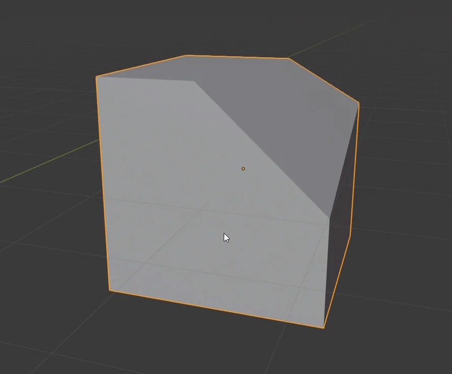
In this article we are going to see how to make sections and cut objects in Blender as seen in figures 1 and 2. For this we are going to use the tools “Knife” and “Bisect”.
Fig. 1: Bisection of the cube.
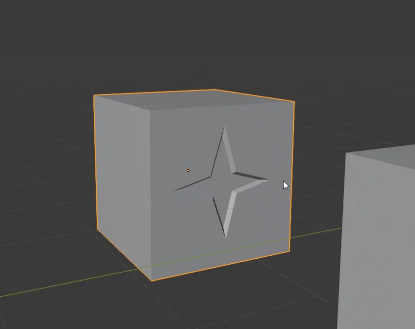
Fig. 2: Cut on one side to form a crack
If you prefer to watch a video I have the right video for this topic:
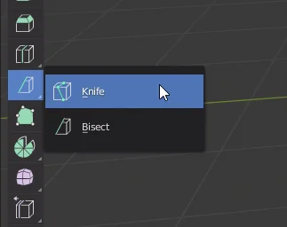
The tools we are going to use are Knife and Bisect, we can see them in figure 2. The knife can be accessed quickly with the K key.
Fig. 3: These are the tools for cutting or sectioning objects in Blender.
Fig. 4: All the faces that are going to participate in the cut must be selected.
Bisect Tool
Let’s start by using the bisecting tool that will allow us to cut an object in two parts.
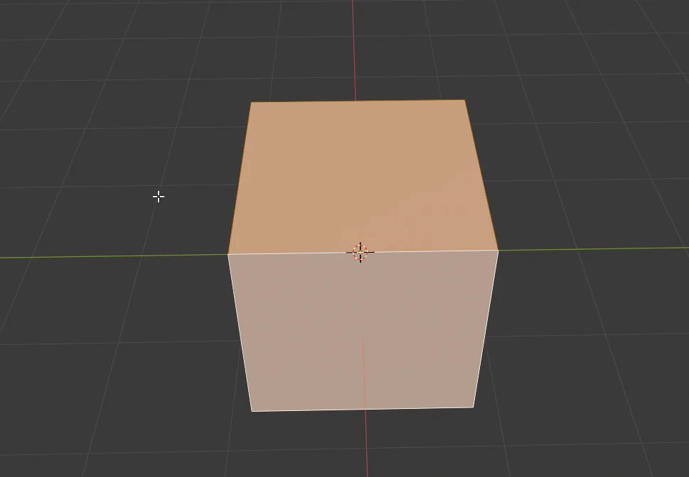
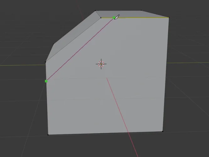
To use this tool, all the faces that will be involved in cutting must be selected. Then we mark two points on the object (figure 5), this will draw a plane perpendicular to the view and that passes through these two points, on this plane we will make the cut of the object. In figure 6 we can see the result.
Fig. 5: With the Bisect tool two points must be marked to make the cut.
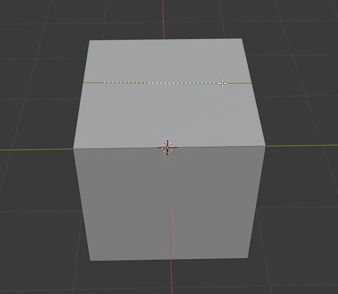
Fig. 6: The cube was divided into two parts.
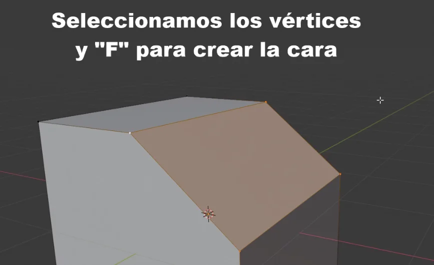
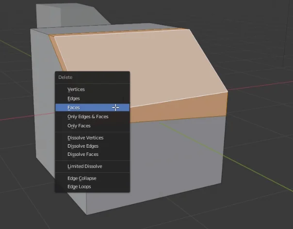
Taking the result of figure 6 we can remove the top and create a new face, getting the result we were looking for.
Fig. 7: We can remove the top and create a new face selecting the vertices and pressing F.
Knife Tool
Now let’s look at the knife tool, the shortcut is the letter K.
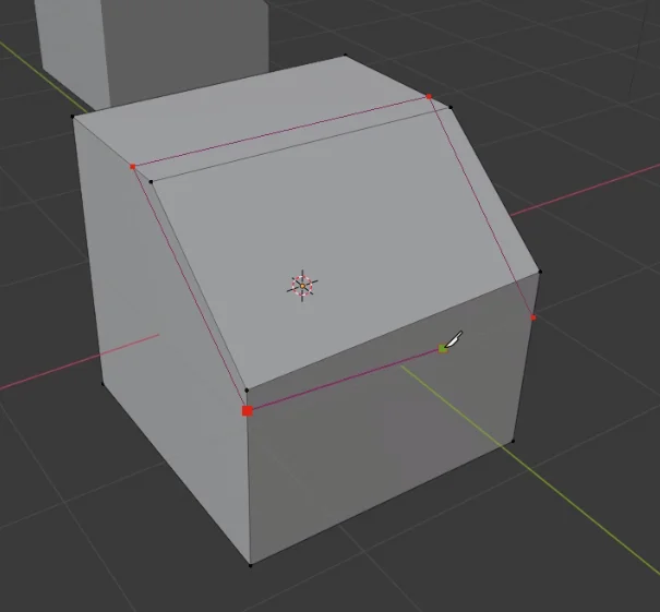
With the knife we can obtain a similar result as with the bisect tool, we mark the points where the cut will be made and at the end we press Enter.
Fig. 8: With the knife tool we can achieve a similar result.
Fig. 9: We mark the vertices of the cut and press Enter at the end.
Fig. 10: New faces have been created as a result of cutting.
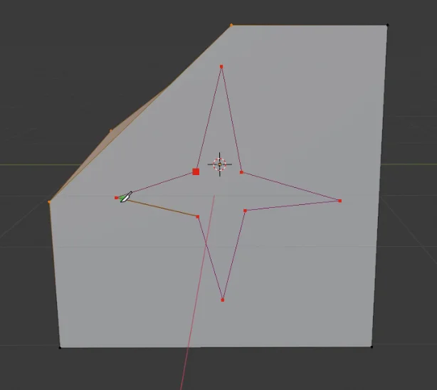
The knife tool allows us to make irregular cuts in any part of the object, in this case we are going to make a crack on one of the faces making a star-shaped cut.
If we double-click while making the cut, the end point will automatically join the starting point.
Fig. 11: With the knife tool you can make irregular cuts in any part of the object.
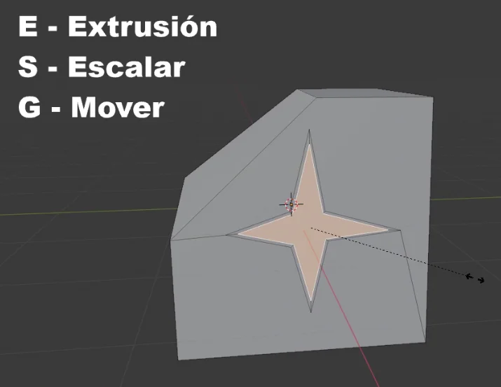
To create the crack we select the new star shaped face, press E to extrude, S to scale and make that new face smaller and the G key followed by X to move the face in the X axis direction.
Fig. 12: At the end of the cut we have a new face that we can manipulate.
Introduction
In this article we are going to see how to create a simple 3D text in Blender from any font of your choice either from the Fonts folder of the system or any downloaded font from the internet. The procedure consists of creating a Text object that is a resource that Blender has to generate texts and configure different parameters such as alignment, font size and others. With this we obtain an editable text, from there we can convert that object into a Mesh, that is to say a 3D model with vertices, edges and faces.
For a visual breakdown of this subject, you may find my video discussion helpful.
1. Get the font file to be used. It can be a font from the Windows > Fonts folder, or a downloaded font, from pages like 1001Fonts or DaFont for example.
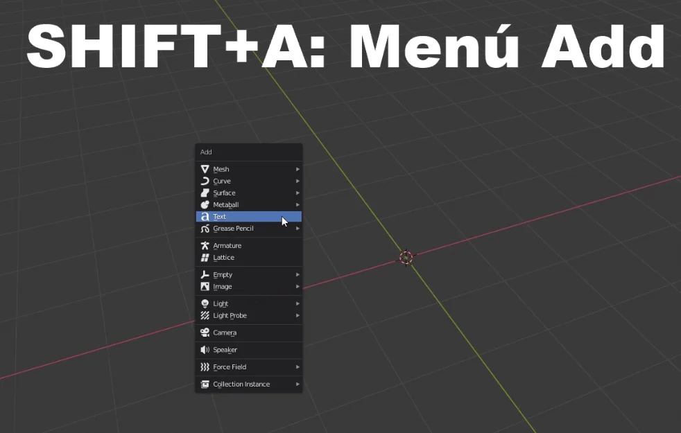
2. In Blender, while in object mode, press SHIFT+A and add a “Text” object.
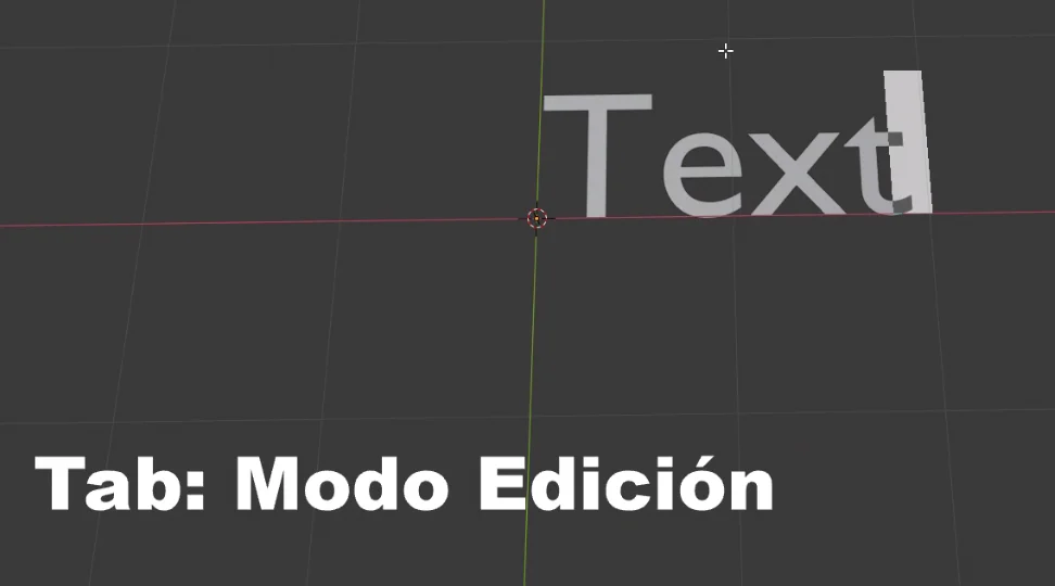
3. With the text object selected, enter the edit mode with the TAB key and write the text.
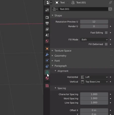
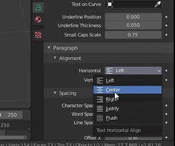
4. In the properties window (the window where you select the rendering engine or create materials), go to the “Text“ tab, which has an icon with the letter “a”, there you can select the font in the “Font” section and modify other text properties such as alignment.
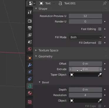
5. In the same “Text” tab go to the “Geometry” section and increase the “Extrude” parameter, with this we will be able to modify the volume of the text.
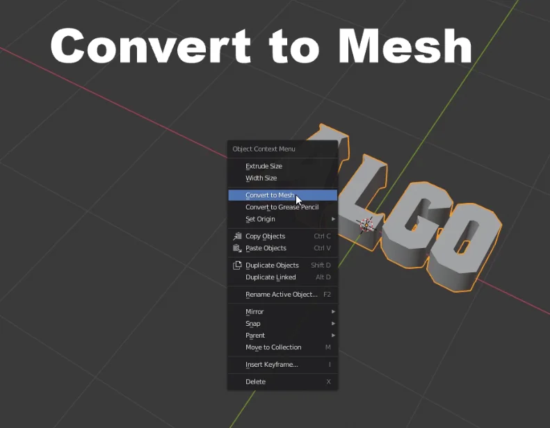
6. When we finish editing the text we return to object mode, right click on the text and choose the option “Convert To Mesh“. This will turn the “text” object into a 3D model with vertices, edges and faces that we can edit.
Detailed procedure for making 3D text in Blender
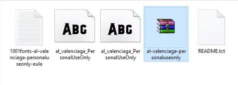
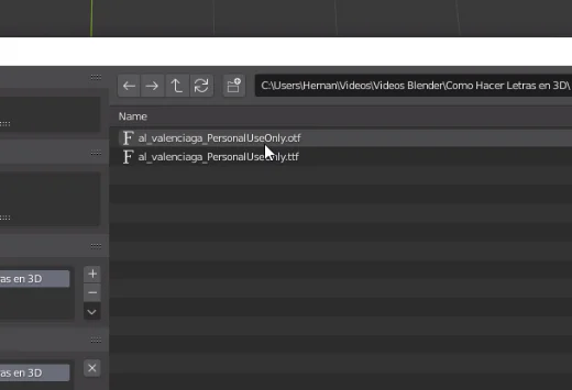
In my case I’m going to download a font from the “1001 Fonts” page. If the font you like is already installed on your system, you can find it in the path “Windows/Fonts/”. Make sure you know the location so you can locate it in Blender.
Fig. 1: We chose a font for the 3D text.
In object mode, press SHIFT + A and add a new text, as shown in figure 2. Then, with the text selected, press Tab to enter edit mode and write the text you want.
Fig. 2: We add a text object.
Fig. 3: With Tab we enter the editing mode and write the text.
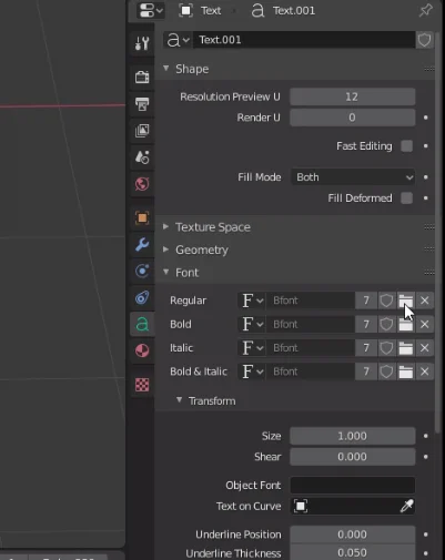
When we have a Text selected a tab appears where we can configure all the properties, we can see it in figure 4. Inside that tab we go to the Fonts section and click on the button to open (figure 5).
Fig. 4: Let’s go to the text tab that appears when we have a text object selected.
Fig. 5: In the Font section we click on the button to open the font.
Using the explorer we look for the font we have chosen.
Fig. 6: We select the font in the explorer.
I’m going to center the text on “Paragraph – Alignment” (figure 7) and to make the letters 3D we go to the “Geometry” section and give a non-zero value to “Extrude”.
Fig. 7: We can align the text.
Fig. 8: To give volume to the text we go to “Geometry” and increase the value “Extrude”.
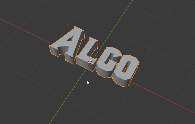
This makes the text now have depth, as we see in figure 9.
Fig. 9: We set all the necessary parameters until we obtain the desired result.
Convert Text Object to Mesh in Blender
When we finish editing the text we return to the object mode, right-click on the text and choose “Convert To Mesh”, this will make the text object become a 3D model.
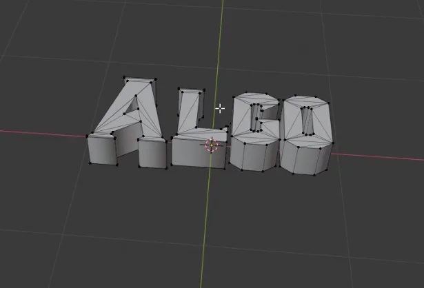
In figure 11 we see the geometry of the 3D letters.
Fig. 10: We convert the text object to Mesh, that way the letters will become a 3D object.
Fig. 11: When entering the editing mode we can see the geometry of the 3D letters.
Introduction
Want to create holes in your Blender models? This tutorial covers how to use the Boolean modifier in Difference mode – a technique for subtracting one object’s volume from another. You’ll learn the workflow for cutouts, plus common pitfalls to avoid. For visual learners, we’ve included a step-by-step video demonstrating the entire process.
For a visual breakdown of this subject, you may find my video discussion helpful.
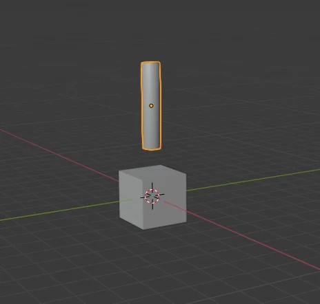
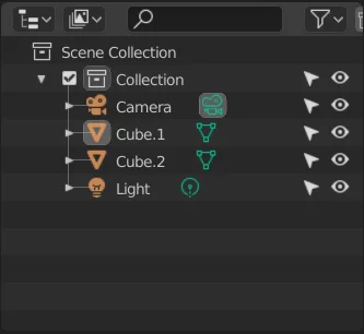
We are going to take a cube and make a hole in it using a cylinder, as shown in figure 1.
Fig. 1: We start with a cube and a cylinder.
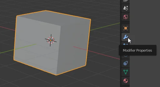
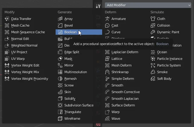
Select the cube and go to the “Modifiers” tab, shown in figure 2. Then add the Boolean modifier, as shown in figure 3.
Fig. 2: Select the cube and go to the modifiers tab.
Fig. 3: We added a Boolean type modifier
In the “Object” field of the modifier we have to assign the object that is going to make the cut, in our case the cylinder. We can use the eye dropper to select the cylinder or we can choose it from the list.
The operating mode must be “Difference”, so that all the space occupied by the cylinder inside the cube is eliminated, as shown in figure 4.
Fig. 4: In the Object field, we select the cutting object, in this case the cylinder.
Then we place the cylinder where we want the hole to be made.
Fig. 5: We position the cylinder according to how we want the hole.
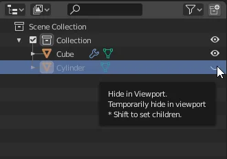
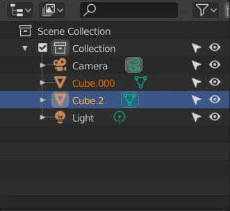
If we go to the Outliner and hide the cylinder (figure 6) we see that the piece has already made the hole.
Fig. 6: We hid the cylinder in the Blender Outliner to see the result.
Fig. 7: Hiding the cylinder shows that a hole has been made in the workpiece.
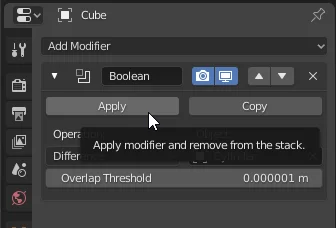
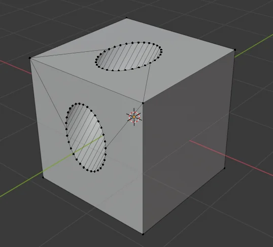
When we don’t have to make any more changes, we can apply the modifier to make the cut effective. In figure 9 we see how the geometry looks after applying the modifier.
Fig. 8: We apply the Boolean modifier to make the cut effective.
Fig. 9: En la geometría podemos ver el corte.
Introduction
This download for Unity consists of a 3D model of an antique style wall clock, Roman numerals and a wooden frame. The hands are functional.
The download includes the PBR textures with 512 x 512 resolution.
In the following video you can see how to import packages in Unity.
Download Unity Package
Content of the Package
Inside there is a 3D model of the clock, three textures (Albedo, Metallic and Normal). Two scripts to set the clock and test that functionality. A scene in which everything is configured, when you open this scene and enter the game mode, the clock model will show randomly different times.
How to use the Wall Clock for Unity
The Clock is controlled using the “GDTClock” script, this has a public function called “SetTime” that allows to set the time.
In simple terms, to use the clock we must create a Script that controls it, inside this Script we must define a reference of the class “GDTClock” and find the reference of this object in the hierarchy, this last one we can do manually defining the object “GDTClock” as public or serialized and then dragging the GameObject of the Clock to the field in the inspector. The “WallClockTest” script inside the package shows how to use the clock.
In this article we see the instructions we need execute in order to quit the game in Unity, then we will make a button call the exit function when pressed.
In the following video you can see the complete process in which we see how to close the game in Unity, from the creation of a simple Canvas to test the function, to the script with the necessary functions.
Within the “Exit” method we will place a single instruction that will be in charge of closing the game.
Application.Quit();
The idea is that the button on the user interface will execute this function when it is pressed.
For this we select the button in the hierarchy and in the inspector, in the OnClick section we click on the little plus sign to add a new field, we drag the GameObject that has the public function to close the game and using the drop-down menu we look for this function in the list.
Conclusion
We’ve seen very simply how to close the game at Unity. For this we must execute the “Application.Quit()” instruction somewhere in the code. In this case we execute it when we press the exit button of the user interface, but we could do it in different ways.
Now it is time to think about what tasks we should carry out when closing the game and make sure they are executed before the Quit instruction. For example, what information should we save to retrieve in the next session?
EXTRA: Quit application with confirmation dialog
🎁 UNITY PACKAGE: Exit application with confirmation dialog
ABOUT THIS SOLUTION
By clicking in Download you will get a file with “Unity Package” extension. Drag and drop that file into Unity to import it.
When you import this Unity Package you will find a folder with a scene, a script and some extras.
Open the scene and you’ll find detailed information about how this solutions works.
369 Downloads
🟢 How to quit application with confirmation dialog
Introduction
In this article we see how to join and separate objects in Blender. We start by understanding what an object is in Blender, then we start with two separated objects and join them together to form a single object. Finally we take this object composed of two parts and we are going to separate it again into two different Blender objects.
What is an OBJECT and what is a MESH in Blender?
Blender has different working modes, when we are modeling in 3D two of the most used modes are “object mode” and “edit mode“, in object mode we work with the objects in the scene while in edit mode we work with the geometry that a specific object or a set of objects has defined inside them. Objects are entities that have at least one reference point called origin and have an associated transformation, that transformation consists of information about its position in space, its rotation and its scale. An object in Blender can be empty and simply serve to mark a coordinate in space, but normally if we are modeling in 3D the object will have defined a Mesh, which is a set of vertices, edges and faces that are connected in a certain way, the object could also contain several meshes not connected to each other.
Now that we have seen a more precise idea of what are objects and meshes in Blender let’s see how is the process to join and separate objects in Blender.
In the following video we see the process to JOIN and SEPARATE OBJECTS in Blender
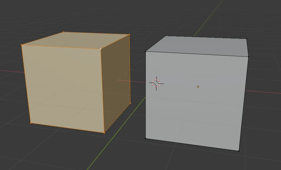
We start from two separated objects as seen in figure 1, in the Outliner of figure 2 we see that they are two separate objects.
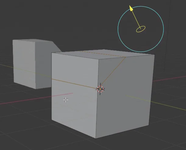
Fig. 1: We start with two separate objects.
Fig. 2: In Blender’s Outliner we can see that these are two different objects.
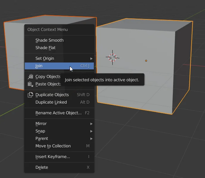
We select both objects using SHIFT and right click to display the menu shown in figure 3. We choose the option “Join” to combine both objects into one.
It is convenient to learn the shortcut CTRL+J to save time.
Fig. 3: Select both objects, right click and use the “Join” option.
In the Outliner we see that we now have a single object composed of both cubes.
Fig. 4: In the Outliner we see that the objects have come together and are now one.
How to separate objects in Blender
Now we want to reverse the process, we start from a single object composed of several parts and we would like to take one of those parts and separate it into a new object.
To do this we enter the edit mode (TAB shortcut) and select all the vertices we want to separate into a new object. In the video I select a vertex of the cube and then I use the shortcut CTRL+L that allows me to select all the vertices that are connected.
Fig. 5: To separate the objects in Blender, we select all the vertices we want to separate.
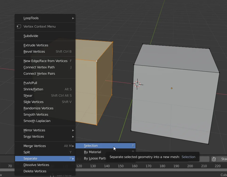
Then we right click to display the menu shown in figure 6 and go to “Separate”. We can also use the shortcut with the letter “P” to display this menu.
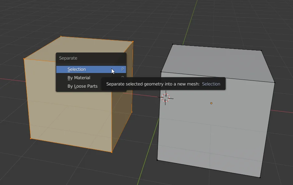
We choose the “Selection” option to separate all the selected vertices into a new object.
Fig. 6: Right click and go to the “Split” option. You can also use the menu shortcut to separate objects with the letter “P”.
Fig. 7: We choose the option “Selection” to separate the selected vertices into a new object.
In figure 8 we see that we now have two different objects in the Outliner.
Fig. 8: In the Outliner we see that the objects have been separated and now there are two.
Introduction
In this article we will see a downloadable solution that consists of a conveyor belt made in Unity, whose operation is controlled using an Arduino plate.
Downloads
In the next package you will find two folders, one with the Unity files and one with the Arduino files.
Inside the Unity folder you will find a compilation to test the simulation and also a Unity package that you can import into your project and access the assets of this simulation.
Upload the program to the Arduino
In the downloads you will find a folder called “Arduino”, which contains the program that reads the digital entries, forms a word and sends it through the serial port.
The program is quite simple so it will work on any Arduino board you can get, in my case I used an Arduino Mega.
In the following video you can see how to record the program on the Arduino board, you will need the Arduino software.
The Arduino program that comes with the download uses pins 2 and 3 for the digital inputs. Pin 2 controls the status of the feeding machine and pin 3 controls the status of the conveyor belt.
There are many ways to connect signals to the Arduino’s digital input, I will show two alternatives using switches.
WARNING BE SURE TO CONNECT THE ELEMENTS TO THE ARDUINO PROPERLY, A SHORT CIRCUIT CAN DESTROY THE BOARD. IT IS NECESSARY TO KNOW THE LEG DISTRIBUTION OF EACH PARTICULAR CONTACT, BETTER IF YOU HAVE A TESTER TO MEASURE CONTINUITY.
Alternative 1: Two-position switch
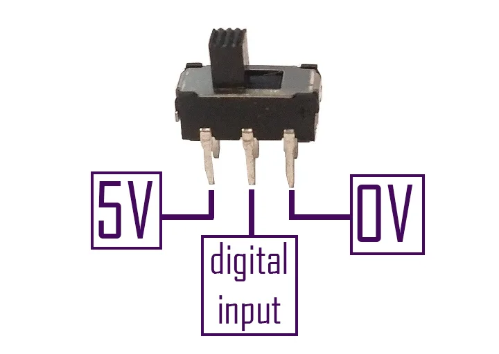
In my case I used two position switches for the digital inputs, in these switches the middle terminal makes contact with one end or the other depending on the position of the switch. Therefore, at the ends we connect the high and low voltage signals (in my case 5 Volts and 0 Volts respectively). The middle terminal of the switch is connected to the digital input of the Arduino.
I repeat the warning, the switch I used is like the one shown in figure 1 and in this particular case it is connected that way.
Fig. 1: Wiring diagram of a two-position switch for digital input of the Arduino
Alternative 2: Pull-up resistor switch
Perhaps you only have one switch, i.e. a contact that closes or opens. In the Arduino’s digital inputs there should be constant high or low voltage signals, we should not leave digital inputs unconnected to anything (connection to the air as we say here) as this will lead to unpredictable behavior.
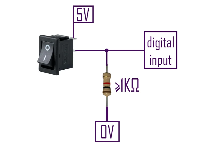
To do this, a small circuit with a pull-up resistor must be implemented, as shown in figure 2.
In this case we use a resistor connected to the GND terminal of the Arduino and the other end connected on one side to the digital input and on the other to the switch, the other end of the switch is connected to the high voltage signal (5 Volt for example).
Fig. 2: Wiring diagram of a pull-up resistor switch for digital input of the Arduino.
The circuit in figure 2 works as follows: when the switch is open there is no current flowing through the resistor, therefore the 0 Volts are transferred to the digital input and the Arduino reads a low level. When we activate the switch the current will flow through the resistance and the Arduino’s input will have a high level signal.
Check if the Arduino program is working
The Arduino program is in charge of reading the status of the digital inputs, creating a binary word that represents those states and sending it by serial port.
If we open the Serial monitor, from the Tools tab, we should see the states of the digital message inputs. As you can see in the following video.
Once we have recorded the program on the Arduino board, we can run the compilation that comes with the download.
When entering the simulation, in the upper left corner there is a button to connect Unity to the Arduino board.
In this part you may have problems with the connection, probably correct this in another version of the solution. To make sure the connection works, the Arduino board must be connected before opening the compilation and the connection process may take several seconds to complete. If after 30 seconds the board is not connected, check the previous step and reopen the simulation and try again.
Video 3: Prueba de la cinta transportadora en Unity controlada por Arduino.
Import package and fix “API Compatibility Level” error
To access the source files of the simulation is the Unity package, you can import it as seen in the following video.
Video 4: Import bundle and fix API Compatibility Level error
When importing the package we will get errors because some scripts cannot access the package with the classes that allow access to the serial port.
To fix this, follow the steps shown in video 4. Go to Edit > Project Settings > Player > Other Settings and in the field “API Compatibility Level” set “.NET 4.x”.
How the Conveyor belt in Unity controlled by Arduino works
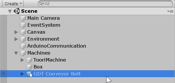
Inside the package is the scene that is seen in the simulation, we can access it and see its elements, in figure 3 we can see the hierarchy of the scene.
In the hierarchy we have three machines, “Toori Machine” is the machine that places objects on the conveyor belt. “GDT Conveyor Belt” is the conveyor belt and “Box” is the box where the objects fall and are destroyed.
Fig. 3: Hierarchy of the scene that comes inside the package.
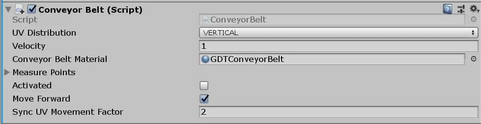
Conveyor Belt
The conveyor belt is a 3D model with a structure and a belt.
To achieve the animation of the operation what is done is to add offset to the UV map of the texture. In this case, as the texture is vertically distributed, we add offset to the Y component of the UV map. When the UV map has an offset of 1 in the Y component the texture returns to the initial state.
So to achieve the effect of the conveyor belt moving forward or backward we gradually increase the UV map offset on one of the components.
To make the belt transport objects, you have a Collider box in Trigger mode that detects when an object is on the belt, these objects must have a RigidBody component assigned to them.
Fig. 4: Script that controls the conveyor belt in Unity
Then in the Conveyor Script you define the OnTriggerStay function that will be called when an object is on the conveyor belt. This function will be in charge of moving the object, to synchronize the movement of the belt with the movement of the object there is a parameter in the inspector called “SyncUVMovementFactor”, by default it is set to 2, as shown in figure 2.
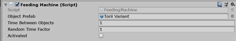
To make the simulation a little more complete, a machine that places objects on the conveyor belt is included. This machine is controlled with the “FeedingMachine” script and also has a public method that allows you to turn it on or off. This machine will be controlled with the digital input 2 of the Arduino.
Fig. 5: Script that controls the machine that places objects on the conveyor belt
In the inspector we can place the prefab of the objects to be placed on the conveyor belt and we can change the times between one object and another.
Communication between Arduino and Unity
Esta parte se resuelve utilizando una versión modificada de la solución WRMHL compartida por el equipo RELATIVTY. Te animo a visitar los links para ver la solución original y los proyectos.
This part is solved using a modified version of the WRMHL solution shared by the RELATIVTY team. I encourage you to visit the links, see the original solution and the projects they have.
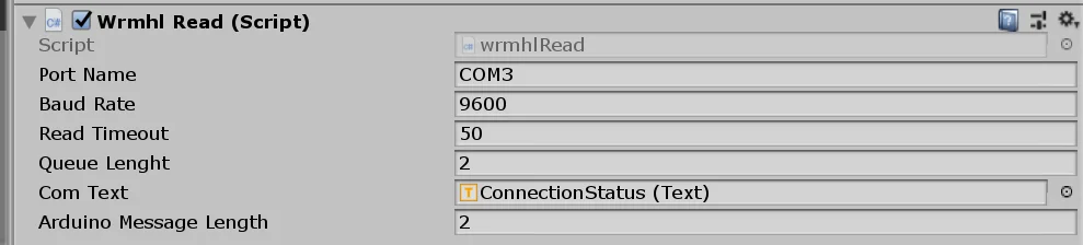
In order to communicate Unity with Arduino you must have a GameObject in the hierarchy with the “wrmhlRead” script assigned.
Fig. 6: Script that controls communication between Arduino and Unity
I have added an integer called “arduinoMessageLength” in the inspector, which indicates the length of the binary word that is sent from the Arduino. This is used to correctly synchronize Unity with Arduino in case there are more devices using the serial port.
In our case, since we sent a two-digit word from the Arduino, you must put two in that field. If you add more digits to the word, you must modify this field appropriately.
The reading of the Arduino message is done in the “ReadMessageAndAction()” method. Here inside we can perform the action we want in Unity. In our case we execute the public methods of the ConveyorBelt and FeedingMachine scripts, to activate or deactivate the machines according to the Arduino’s command.
Conclusion
We’ve seen how the conveyor belt solution works at Unity controlled by Arduino.
With the files provided you can create a new simulation according to your needs.
This website uses cookies to improve your experience. We'll assume you're ok with this, but you can opt-out if you wish. Cookie settingsACCEPT
Privacy & Cookies Policy
Privacy Overview
This website uses cookies to improve your experience while you navigate through the website. Out of these cookies, the cookies that are categorized as necessary are stored on your browser as they are as essential for the working of basic functionalities of the website. We also use third-party cookies that help us analyze and understand how you use this website. These cookies will be stored in your browser only with your consent. You also have the option to opt-out of these cookies. But opting out of some of these cookies may have an effect on your browsing experience.
Necessary cookies are absolutely essential for the website to function properly. This category only includes cookies that ensures basic functionalities and security features of the website. These cookies do not store any personal information.