In this article we will see the concept of electrical resistance, resistive elements and we will analyze a simple circuit to see the effect it has on the current.
What is electrical resistance?
It is a property of matter that indicates the difficulty that the electric current has in crossing it.
There are materials that have a low resistance, in which the current can flow easily, and there are other materials that have a high resistance, in which it is more difficult for the current to circulate.
Materials with low resistance are called conductors and materials with high resistance are called insulators.
Resistive elements
Fig. 1: Different types of resistance or resistors.
On the other hand “Resistance” is the name given to certain elements that are built with the purpose of having a predictable resistance value, we can see some examples in figure 1.
These elements are used in circuits to make currents behave in a certain way.
Effect on the current in a simple circuit
We are going to simulate a simple circuit with a voltage source of 10 Volts of direct current connected to a resistor. The objective will be to analyze how the current is in the circuit.
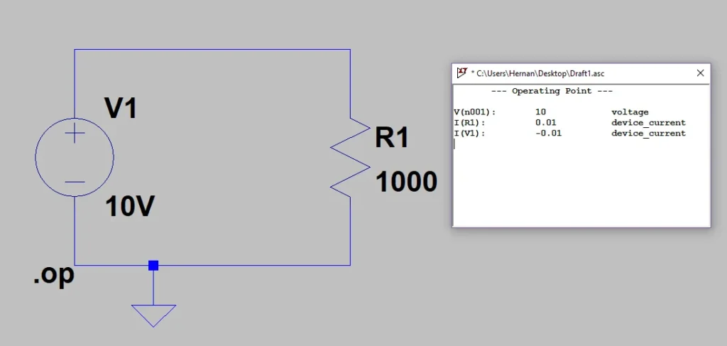
Fig. 2: Circuit with 10V source and 1K resistance Ω , current 10mA.
In the first case, illustrated in figure 2, the resistance of the circuit is 1000Ω or 1KΩ (kilo ohm) as it is most often called.
When running the simulation we see that the resulting current is 0.01A (Ampere) or 10mA (milli Ampere).
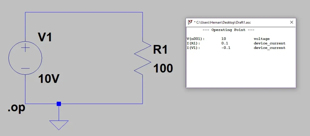
Fig. 3: Circuit with 10V source and 100mA resistance Ω , 100mA current.
If we now change the resistance value to 100 Ω and simulate again, the current now increases to 100 mA (Figure 3).
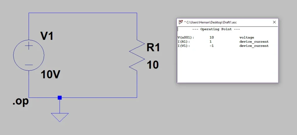
In the third test we give the resistance a value of 10 Ω and when simulating the current increases to 1 A, figure 4.
Fig. 4: Circuit with 10V source and 10V resistor Ω , current 1A.
What we observe is that when the resistance value decreases, keeping all the other parameters of the fixed circuit, the current increases.
Conclusion
Resistance is a property that determines how good a material is as an electricity conductor.
Materials with low resistance such as metals are good conductors of electricity, while materials with high resistance are called insulators, such as plastic.
In a simple electrical circuit we can see how the current behaves when we change the resistance, leaving the other parameters fixed. We see that they have an inverse relationship, the lower the resistance, the higher the current.
Introduction
Electricity is so present in our daily lives that we often forget its importance until suddenly a blackout occurs. In this article we will look at the concept of electricity, its application in the home and industry. We are also going to delve into the nature of matter in order to understand where electricity comes from as we know it.
Electricity – home and industry
Preserving our food, heating the water in the house, heating and entertainment are some examples of the application of electricity in the home.
In the industry it is used to run machines that require power, such as motors and fans. It is also used to power control systems.
How do all these electrical devices work?
In all cases what happens is that an electric current circulates through these devices, excites their internal circuits and produces an effect.
Types of electric current
There are two types of electric current, direct current (DC in Spanish, DC in English) and alternating current (AC in Spanish, AC in English).
Direct current is generally used to power digital systems such as LED TVs, computers and radios. While alternating current is used to run motors, resistors to generate heat, among others.
It is possible to convert one type of current into another by using the appropriate device. The most common is the transformer we use to charge the smartphone or notebook, these machines are fed by the alternating current from the household sockets and convert it into direct current.
Power Sources
We know thaenergy has to “come out” from somewhere, in general our house is connected to the electrical network of a city or town and we have plugs or sockets.
This energy comes from power plants that use machines that transform a type of energy such as wind, sun or fossil fuels into electrical energy.
Fig. 1: Wind turbines in Rawson, Argentina. Source Wikipedia.
Fig. 2: Polycrystalline solar panel.
In remote places where the power line does not reach, it is necessary to resort to other solutions in order to obtain electrical energy. For example to install solar panels or generators and to apply much the rational use of the energy.
Fig. 3: Generator I received just at the time of writing this article.
What is electricity?
We have talked about its application, the principle of operation of electrical machines and the types of current, now let’s go a little deeper into the nature of matter to understand more deeply
In antiquity it was discovered that matter could be “loaded” in some way, since when rubbing certain materials with others a force of action appeared at a distance like gravity. We are talking about the typical experiment that we do in primary school in which we rub the ruler on our hair and then we can make bits of paper adhere to it.
In addition it was discovered that there were two types of charges, which were later referred to as positive charge and negative charge.
Observing the interaction between these charged materials it was noted that charges of the same type are repelled and charges of dissimilar type are attracted.
These charges present in matter are what give rise to the electric current.
Conclusion
Electricity is widely used in everyday life to power all kinds of devices. The general principle of all these devices is an electric current that circulates through their interior producing an effect.
There are two types of electric current, direct current (DC) and alternating current (AC). We can convert one type of current into another by using the appropriate device.
Electricity is generated by machines that transform different types of energy into electrical energy.
In the matter there are two types of charge, positive charges and negative charges. If two charges of the same type face each other, the result is a repulsive force between the two. If two charges of a different type face each other, a force of attraction appears between them.
Introduction – Setting up the scene
In this article we will see a very simple trick to bend objects in Blender, for this example we will use Blender’s default cube, here is a couple steps you can do to follow exactly this tutorial.
Create a new Blender file.
Select the default cube and go into edit mode.
Press A to select all vertices.
Press S, then X and write “10” to scale the cube in the X axis, ten times its original size.
Press CTRL+R and move the cursor until you see the yellow square shape from the image below. Turn the mousewheel a couple times to get extra subdivisions and left click to apply the subdivisions. Right click to apply with any displacemente.
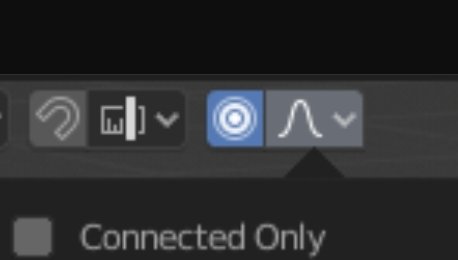
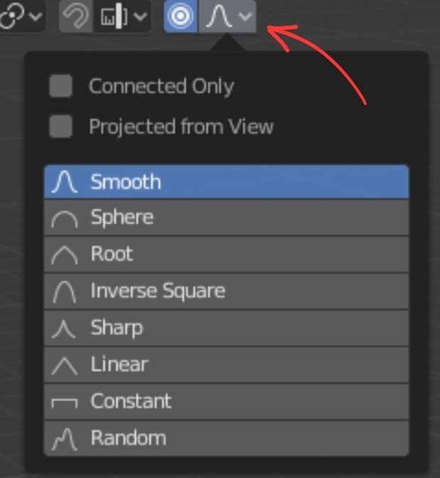
You can bend an object in Blender using the “Proportional Editing” feature by enabling the icon shown in the image below or by pressing the “O” shortcut.
Press LEFT-ALT and click on and edge of the object to select and Edge Loop. Press G to grab that edge loop and move it around.
Proportional Editing option allows you to transform now only the selected vertices but also vertices that are nearby with an intensity that is proportional to the distance.
You can change that intensity by spinning the mousewheel.
This editing option is applied also for rotation and changes of scale, so you can use it to apply different transformations to an object.
If you press the icon from the image below you will see different options to apply to the proportional editing option, like the “Connected Only” checkbox that makes the editing affect only those vertices who are connected to our selected vertices. You can also choose a different deformation pattern.
In this article we will see how to apply the glow effect in Blender for the Eevee engine, this effect is also kwown as bloom and it’s a post processing effect, that means is an effect that is applied after the render process.
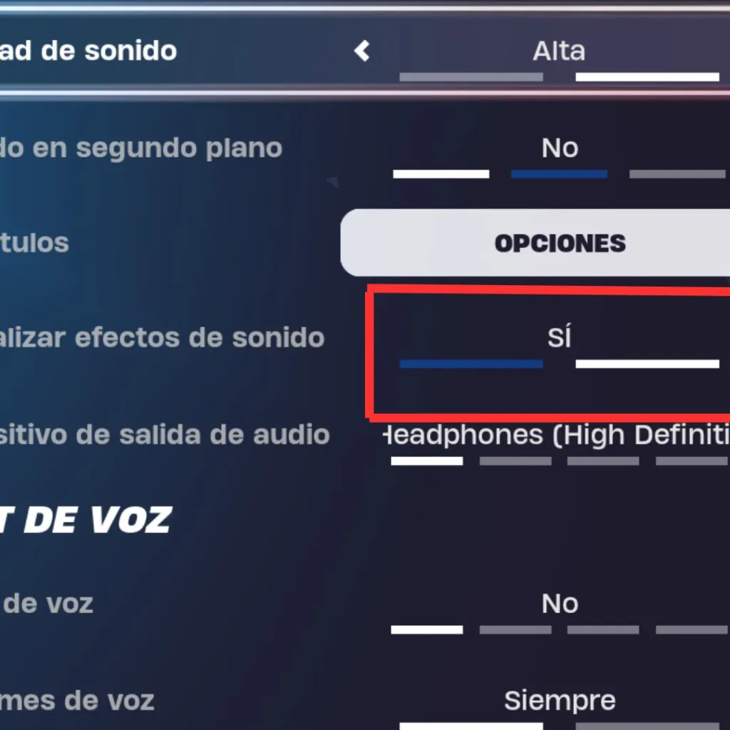
This functionality not only lets you see the steps on the screen, but also the enemy shots and chests near your position. In addition, by activating this option, you will be able to detect enemies better and know their location more easily.
Step-by-step procedure for displaying on-screen steps in Fortnite.
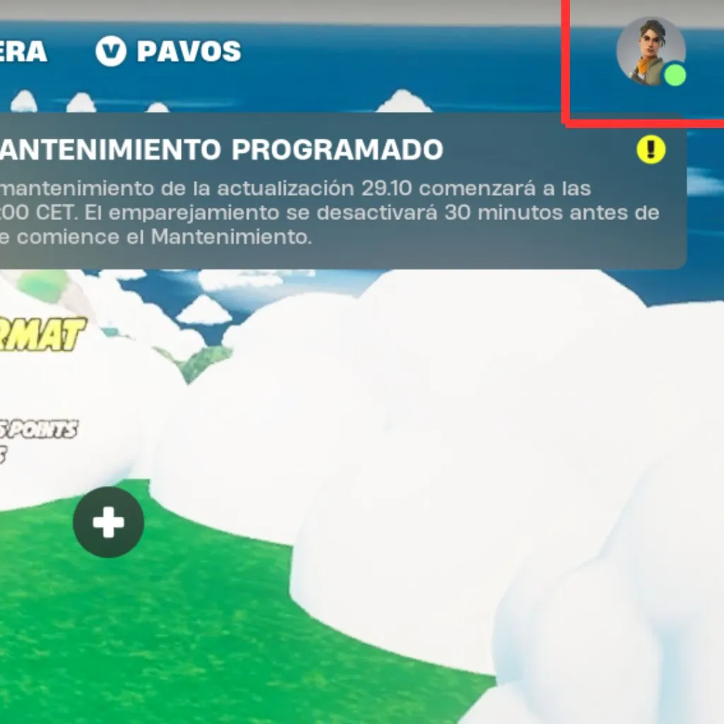
Step 1: When you are in the Fortnite lobby, you will need to access the game menu that will appear as an icon on the top right of the screen.
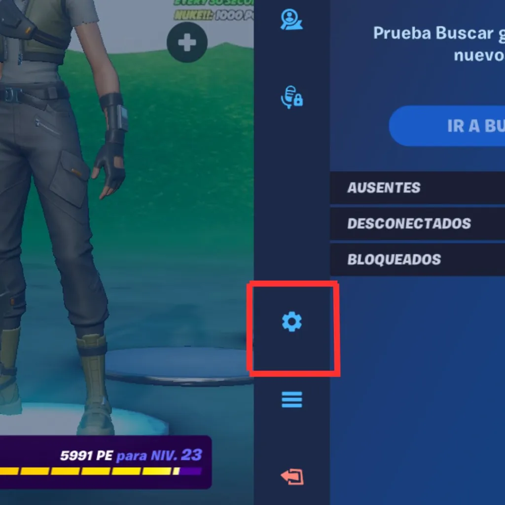
Step 2: Once you have accessed the menu, you must go to the bottom of the menu until you find the gear. You will then be able to enter the settings.
Step 3: After completing the above steps, you will be in the settings. There you should find the “sound” section, which is located at the top of the screen, right next to “video”.
Step 4: In the “sound” section, scroll down until you find the “display sound effects” option and activate it.
Introduction
Did you know you can trigger sound effects on mouse hover in Unity—without writing a single line of code? By leveraging built-in UI components like Event Triggers and Audio Sources, you can easily add interactive feedback to buttons and other UI elements directly in the Editor.
For a visual breakdown of this subject, you may find my video discussion helpful.
What do we need to play sounds on mouse hover in Unity
We basically need three elements in order to play sounds on mouse hover over UI elements, we need a way to play the sound, we need the sound clip to be played and we need a way to detect the mouse hover event over UI elements. Let’s analyze these three elements:
Create at least one AudioSource object in the scene to play the sound
You can create easily a new AudioSource object simply by right clicking in the Hierarchy window, go to audio and click on “AudioSource”, this will create a GameObject with an AudioSource component assigned to it, this AudioSource has the “Play On Awake” checkbox enabled by default so you have to disable it, otherwise the Audio Clip will be played on Start.
Audio files to play on mouse hover
The file of the sound you want to play on mouse hover over UI elements, I suggest you use files with the WAV or OGG format. You can assign the AudioClip to the “Clip” variable in the AudioSource component.
Event trigger component attached on the UI element
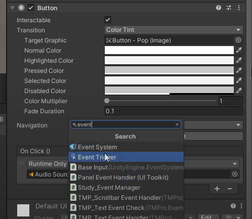
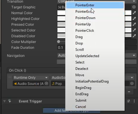
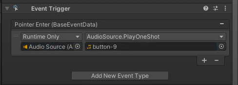
We add an EventTrigger component to our button (See Figure 1) and this allows us to detect different events on this buttons, events like when the mouse cursor hovers over the button, also when a click is made on a button and many other options. In our case we are intereseted in the “Pointer Enter” event which is called when the mouse cursor hovers for the first time a UI element (See Figure 2).
Figure 1: Adding an EventTrigger component to the button.
Figure 2: Adding the PointerEnter event to the EventTrigger component
How to PLAY SOUNDS on MOUSE HOVER over UI elements in Unity
Once we cover all the previous three steps needed to play sounds on mouse hover in Unity we need to properly configure them. Here is a step by step guide to do it.
Select your button, in the inspector click on “Add Component” and look for the “Event Trigger” component.
Click on “New Event Type” in the Event Trigger and select “Pointer Enter”.
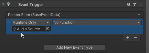
Create a new AudioSource GameObject (or use an existing one) and drag that GameObject to the “Pointer Enter” event (See Figure 3).
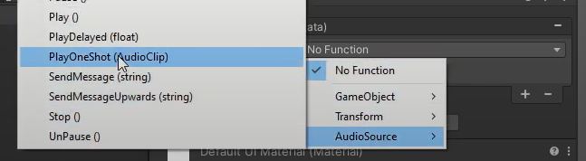
Using the drop down menu of the “Pointer Enter” event go to the AudioSource section and look for the “PlayOneShot” function (See Figure 4).
Drag the Audio file with the sound you want to play on mouse hover to the field of the “Play One Shot” function in the “Pointer Enter” event (See Figure 5).
Play and test
Figure 3: Assign the GameObject with the AudioSource component in the PointerEnter event.
Figure 4: Choose the “PlayOneShot” function using the dropdown menu.
Figure 5: Assign the audio clip you want to play on mouse hover.
Examples of using hover-triggered sounds in Unity UI
1. Basic Button Feedback
Use Case: Play a subtle “click” or “hover” sound (e.g., a soft beep or swoosh) when the mouse passes over a menu button. Why? Enhances user experience with tactile feedback. Implementation:
Attach an Event Trigger component to the button.
Add the “Pointer Enter” event → Link to an Audio Source with your sound clip.
2. Game Menu Interactions
Use Case: A “rustling paper” sound when hovering over menu tabs (e.g., in a fantasy RPG). Why? Reinforces the game’s theme and immersion. Pro Tip: Use 3D spatial sound if the UI is part of the game world (e.g., a diegetic menu).
3. Accessibility Cues
Use Case: A “ping” sound for visually impaired players to confirm UI selection. Why? Makes navigation more inclusive. Optimization: Use a low-latency audio format (e.g., .wav) to avoid delay.
4. Dynamic UI in Simulations
Use Case: A “mechanical beep” when hovering over interactive cockpit buttons (e.g., flight simulators). Why? Mimics real-world interfaces for realism.
5. Mobile/Web UI
Use Case: A “vibrato pluck” sound for hoverable icons (even on touch devices via “Pointer Enter”). Caution: Ensure sounds are short (<500ms) and non-repetitive to avoid annoyance.
Bonus: Use pitch randomization (e.g., audioSource.pitch = Random.Range(0.9f, 1.1f)) to avoid monotony.
Introduction
There are several formats for exporting 3D models in Blender that are compatible with Unity, I recommend that you use one of the following two, the .FBX format or use the Blender file in .Blend format directly.
Before moving on I leave a video showing how to export 3D model in FBX FORMAT from Blender to Unity
In the following video we see not only which format to use to export from Blender to Unity and how to do it, but also other details such as creating new materials in Unity, configuring the textures and assigning those materials to the 3D model in Unity, overwriting the material that is defined in Blender.
If you use the FBX format to export your Blender models to Unity, several things will be packed inside the file besides the 3D models. Some of them are the following:
The hierarchical structure defined in the Outliner will be exported practically the same or very similar and we will see that hierarchical structure in the hierarchy window in Unity.
Object names defined in Blender will also be used in Unity.
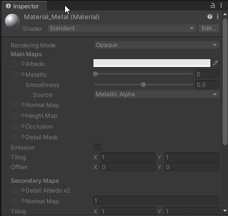
The materials defined inside a 3D model in Blender will be present inside the imported file in Unity and will be applied to the 3D model, but in principle they are locked (see figure 1), they cannot be edited, to do so they must be extracted from the FBX file.
The base color chosen in the material will be the same as the one applied to the material in Unity. This for the Principled BSDF shader.
Textures connected to the base color and normals input will be present in Unity as long as the texture files are present when importing the FBX file into Unity. Those textures will be connected to the Albedo and Normals map in Unity.
Animations made with Dope Sheet and Nonlinear Animation clips will be included in the FBX file format.
Objects such as lights and cameras in Blender will be exported as lights and cameras in Unity.
Fig. 1: Material defined in Blender is locked in Unity. To use it you have to extract it from the file.
Disadvantages of using FBX format
One of the main disadvantages is updating the exported model when making changes in Blender. What I do is to replace the file found in the Unity folder with the new exported Blender file. SEE THE PROCEDURE FOR UPDATING MODEL CHANGES IN THE VIDEO ABOVE.
Using the Blender file directly in Unity (.Blend format)
You can use the Blender file directly in Unity and you will have access to most of the items listed above corresponding to the FBX format.
In specific cases problems might occur, for example when changes are made in the version of Blender or Unity, it has happened to me that the Blender file could not be used, but then in subsequent updates the problem was solved.
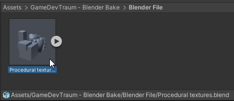
Fig. 2: Blender file inside a Unity project folder. The file can be opened by double-clicking and you can drag it into the scene to use it.
Advantages of using the .Blend file directly in Unity
For me the main advantage of using the Blender file directly in Unity is the convenience and ease of making changes to the model. With this method we can open the file directly by double clicking it in Unity, edit it, save it and then in Unity the changes are automatically updated.
Disadvantages of using the .Blend file directly in Unity
One of the most important disadvantages of working directly with the Blender file in Unity is the loading times, you may feel that Unity works slower, since it takes a while to process these files, when we add them to the scene and when we modify them, it may be something quite annoying depending on the capabilities of your computer. Although if we think about it, that waiting time may not be as long as the time it takes to re-export in FBX format, replace the file and still wait for the processing time Unity spends on that task.
Another important disadvantage is the fact of working with animations, I have not yet found a good way to work in Unity with a .Blend file with several animation clips made in Blender.
A disadvantage, perhaps not so important given the capabilities of devices nowadays, is that the .Blend file is heavier than the FBX file and also Blender makes a backup copy for each file, so the total weight is even bigger.
What are “COMPONENTS” in Unity and what are they for
A COMPONENT in Unity is a set of data and functions that define a specific behavior. Components are assigned to scene elements called “GameObjects” and give that object a particular behavior. In this article I’m going to share everything I know about components in Unity that I consider important to be able to improve your Unity engine management. Let’s start with one of the most important things:
In general, whatever we want to do in Unity we are going to achieve it through components assigned to GameObjects.
For example if we want to make an object be affected by gravity, if we want to be able to control the object with a controller or keyboard inputs, if we want to play sounds, if we want to display images on screen. All this and more can be achieved using different components assigned to GameObjects of the scene in Unity.
Predefined components in Unity
Fig. 1: Some predefined components of the Unity engine.
The Unity engine has defined by default a wide variety of components that achieve different behaviors, we can see them by selecting a GameObject from the hierarchy and in the inspector click on the “Add Component” button, shown in figure 1, there we will have all the available components sorted in different sections depending on the task they do.
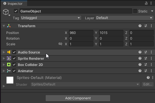
Some examples of these predefined components are AudioSource components that play sounds, SpriteRenderer components that display sprites (images) on the screen, a MeshRenderer component that can display a 3D model on the screen and an AnimatorController component that can control a set of animations and the different transitions between them.
How to CREATE new components in Unity
The components in Unity are nothing more than programming scripts, in the case of the components that are defined by default in Unity are scripts that can not be modified, but the key in all this is that WE CAN CREATE NEW SCRIPTS and by doing so WE ARE CREATING NEW COMPONENTS IN UNITY, these scripts can be assigned to the GameObjects, exactly like the default Unity components.
When assigning a Script to a GameObject, a Script that is nothing more than a component customized by us, Unity will execute this Script, it will execute its instructions, which will allow us to achieve anything we want.
In order for Unity to evaluate a script or a component, some conditions must be met, as we will see below.
How to make a component work in Unity
For any component to do its job in Unity, four conditions must be met, we will list them below and then expand the information about each condition.
The scene that is loaded during execution is the one containing the component.
The component must exist in the scene.
The component must be ACTIVE.
The component must be assigned to an active GameObject in the scene.
If these four conditions are met, the component will perform its programmed task.
It should be noted that in some cases the component may not seem to be doing its job, take the case of an AudioSource that plays a sound, there may be times when the sound is not played, but this does not mean that the component is not working, if the four conditions mentioned above are met Unity is evaluating its behavior, only that its behavior at that time may be not to play the sound until the order of playing is given for example.
Condition 1: The scene where the component is located must be loaded.
An application made in Unity can be divided into different scenes and each scene has its own defined elements. When starting an application in Unity it will automatically load the scene that has been defined with index 0 in Unity’s Build Settings and also at any time we can switch from one scene to another, for example by pressing a “Play” button in the main menu we can load another scene where the gameplay is built.
Fig. 2: Scenes that were added to the compilation of the game or application. At startup, scene 0 will be loaded automatically.
The components in Unity are assigned to GameObjects and the GameObjects belong to a particular scene, therefore if the component we are interested in is in a scene that is not loaded at a certain moment, then its behavior will not be executed, simply because that component does not exist at that precise moment.
Condition 2: The component must exist in the scene.
Fig. 3: Assigning a Script to a GameObject creates an instance of the component that defines the Script.
For a component to execute its behavior it must exist in the scene, this means that we have to “instantiate” it, create an instance of the component we want to use. The simplest way to do this is to choose an appropriate GameObject (or create one) and then in the inspector, with the “Add Component” button, add the component we want to use.
This procedure to add a component can also be done through code, that is to say, from a script we can create an instance of a component and assign it to any GameObject we want, for this last one we need to have the reference of the GameObject to which we want to assign the component.
If the component we are interested in is not instantiated, Unity will not evaluate its behavior.
Condition 3: The component must be active in the scene.
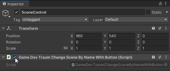
Fig. 4: Activation checkbox of a component in Unity.
Generally the components in Unity have an enable checkbox that allows us to determine if the component is active or inactive, this can be seen in the inspector when selecting a GameObject, in the upper left corner of each component is that enable checkbox, if it is checked the component is active, if it is unchecked the component is inactive.
It is necessary to consider that the activation state can be modified through code, that is to say inside a Script, if we have the reference of that component, we can activate or deactivate it when we need it. Here I have a video in which I show how to do it.
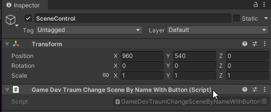
Note: The activation checkbox of a Script that we have created will not be present in the inspector if in the script we do not have defined any of the internal Unity functions (Awake, Start, Update, …). Keep in mind that I am in Unity version 2021.3.18f1, I am not sure if this is true for previous versions and I am not sure, although it is probable, that it is true for later versions.
Read this if you have knowledge of object-oriented programming.
The components in Unity belong to a class called Component, in the hierarchy of classes there are classes like Behaviour or Renderer that inherit directly from the Component class, in this type of components the enable box that we see in the inspector shows the state of an internal variable called “enabled”, a variable that is defined in the Scripts that inherit from classes like Behaviour or Renderer. Let’s take the case of Behaviour objects, these objects are Component but not all components are Behaviours, for example an AudioSource component is a Behaviour and therefore has its enable box. But there are other components such as Transform or Rigidbody that inherit directly from Component and for that reason we do not see the enable box in the inspector.
Condition 4: The component must be assigned to an active GameObject in the scene.
The GameObjects in the hierarchy can be active or inactive in the scene. We can change the state of a GameObject by selecting it and in the inspector, use the checkbox at the top left, if that checkbox is checked the GameObject is active in the scene while if it is unchecked the GameObject is inactive in the scene. It is also possible to activate and deactivate a GameObject through code.
Fig. 5: Activation checkbox of a GameObject in Unity.
If a GameObject is active in the scene, Unity will automatically execute some functions that belong to the active components that are assigned to that GameObject, the most known functions can be the Awake, Start, Update and FixedUpdate functions, but there are many other functions that are part of Unity’s initialization and update cycle.
If the GameObject is not active, these functions will not be automatically executed on the components assigned to the GameObject, however this does not mean that we cannot use those components, even if a component is inactive, we could access it and read some parameter that we are interested in.
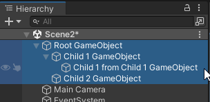
Fig. 6: Hierarchical structure of GameObject within a scene in Unity.
In Unity you can establish a hierarchy between different GameObjects, i.e. a GameObject can act as a parent of other GameObjects. The children of a GameObject will be affected by some things that happen to its parents, for example if we move the parent object, all its children will move together. This behavior also happens with the activation state of the GameObject, if the parent is deactivated, all its children (and the children of its children) will be deactivated as well. For this reason, for a component to work in Unity, not only the GameObject to which it is assigned has to be active, but all the GameObjects that are up the hierarchy.
Introduction
Before I start with useful tips and tricks for Blender I will briefly share with you my history with Blender.
A few years ago I had a serious addiction with Blender which is used to create 3D models and animations, I used it a minimum of 4 hours a day trying to recreate all kinds of things that crossed my mind, particularly nothing artistic but I was able to create structures, furniture and other types of objects based on reference images. 3D modeling was something that made me surprise myself of my own capabilities, every time a rendering was completed I felt very proud of my creation. In retrospect I wasn’t doing very amazing things but they were things I had made myself from scratch and that was amazing. So much time and effort spent 3D modeling with Blender and texturing with Substance Painter paid off and today I can include those capabilities as part of my work as a freelance developer.
Below we are going to review 10 useful tips and tricks for using Blender that have helped me to speed up and improve the modeling process, allowing me to accomplish tasks faster or achieve better results.
#1 – Focusing the camera on the selected object in Blender
We start with a shortcut to center the view or even the rendering camera on the selected object. An extremely important trick because it is something that greatly improves the agility when using Blender. With this shortcut you can say goodbye to all that time trying to correctly place the camera on a 3D model or even on a vertex, the center of an edge or a face.
To use it simply select an object or an element of the mesh and press the dot on the numeric keypad, you will see how the camera is centered on the selected element and also, when rotating the camera, the selected element is the center of rotation.
#2 – Hide all objects or geometry except what is selected in Blender
If you are working on a Blender project that has many objects or an object that has a particularly complex mesh, it can be very useful to temporarily hide certain objects and leave visible only what you need to work with. With this simple shortcut you can easily hide selected objects in Blender and when you need to reveal all the hidden objects again.
To isolate elements in Blender simply select the object or mesh element you want to isolate and press SHIFT+H, this will hide all other elements that are not selected. To make all hidden elements visible again press ALT+H.
#3 – Tip to quickly parent and un-parent objects in Blender
When parenting objects one of them becomes the parent object and the other object or objects we choose become the children, this causes the child objects to be automatically affected by the transformations received by the parent object, for example a movement applied to the parent will cause all the children to move together, the same happens for rotations and scale changes.
To quickly parent one object or set of objects to another in Blender you have to go to the Outliner window where all the objects are located, select the ones you want to parent and then drag them to the object you want to parent them to while holding down the SHIFT key, optionally you can press ALT to keep the transformation of the parent objects.
#4 – Render image with transparency in Blender (works for Cycles and Eevee)
In many occasions it is very useful to render only the visible parts of a 3D model and make the rest of the rendering transparent, for example when you want to create a GIF of yourself dancing and place it in an article about Blender tips.
In the properties window go to the render properties tab and there go to the “Film” section, you will find a checkbox called “Transparent”, checking this will make the parts of the render where there is no 3D model transparent. Make sure you use an appropriate image format that supports transparency, such as PNG.
The normals of a 3D model are a mathematical element that allows to know in which direction is pointing a particular face of a 3D model, sometimes in the modeling process certain normals can be inverted, that is pointing towards the inside of the 3D model and this can bring problems with shading, which means problems in the visualization of a material applied to the 3D model and also erratic behavior with light sources. Another important problem arises if we are creating these 3D models to use in a game engine like Unity, in this engine 3D models are rendered with “backface culling”, this means that if we have an inverted face in the graphics engine will be invisible and we will see through it, to solve this just correct the normals of the 3D model, but first we need to be able to see these normals.
To activate the normals of a 3D model it is necessary to be in EDIT MODE. Then in the upper right corner of the Viewport window click on the arrow that displays the “Viewport Overlays” window, almost at the end of it we will find the “Normals” section where we have 3 icons to display the normals, usually I choose to display them in the center of the faces. We can also adjust the length of the normals.
#6 – Know the number of vertices, edges and faces in our scene in Blender.
When we are creating 3D models we may be interested in knowing information about the geometry of the objects we are creating, for example how many vertices, edges, triangles or faces our model has, this can help us to determine if there is any problem with duplicate vertices and also keep track of how many polygons our 3D model has, if we are creating 3D models to use in a graphic engine like Unity it can be important to keep the amount of polygons within a reasonable number according to the model we are creating, especially if the application is for a mobile or virtual reality device, where there are certain limitations with the hardware.
To display information about the number of vertices, edges, faces and objects in Blender we go to the upper right corner of the Viewport window, click on the arrow that displays the “Viewport Overlays” window and check the “Statistics” box at the top of the window.
#7 – Applying the same material to other objects in Blender
When we select an object and we want to apply a color or give it a metallic appearance for example what we do is create a new material, which by default starts with the “Principled BSDF” Shader and we have different values to configure the material as we wish. But what happens if we have a second object and we want it to have the same material? We might be tempted to create a new material and configure it with the same parameters, it is even possible to copy the parameters of one material and apply them to another.
But there is a better alternative, in Blender we can make that two objects have the exact same material applied, that is to say that one or several material slots are pointing to the reference of the same material, in this way we can create a particular instance of a material that we could call “Pine Wood” for example and reuse that same material in all the objects that need the pine wood texture, this not only avoids that we have many unnecessary copies of a material but also allows us to modify the material and that the changes are applied automatically in all the objects where that material is used.
In this case the video is more illustrative but let’s try to summarize the procedure. With an object selected we go to the Materials tab (sphere icon with checkered texture), then if we click the + sign what we will do is create a new “Slot” for a material within our object, here there are two options, one is to click on “New” which creates a new instance of a material, completely independent of the others, the other option is to select an existing material (which interests us in this case), for this we click the icon to the left of the “New” button and select from the list the material we want to assign to the slot.
#8 – Show animation bones always in front of other objects in Blender
When creating animations with Blender using animation bones it is very useful to be able to see these bones at any moment even if they are hidden inside another object or obstructed by an object.
With the “Armature” object selected, go to the “Object Data properties” tab (which has a humanoid icon and is located above the tab with the bone icon), then go to the “Viewport Display” section and check the “In Front” checkbox.
When we gain some experience with Blender we come across the concept of “Edge Loop”, basically it is a set of vertices on a surface that are connected together and the last vertex of the set is connected back to the first one, the key is that of all the possible connections that can be drawn and that meet these conditions, the Edge Loop is like the loop that is connected in the most coherent way in relation to the other surrounding sets of vertices, it is a concept somewhat difficult to explain but it is easy to understand once we start working with them. An example of edge loop can be one of the rings that forms a sphere or a donut in Blender (the correct name is torus but it looks like a donut), each ring is a set of vertices connected forming a loop and this is an edge loop.
To quickly create an Edge Loop in Blender, select an object, go into EDIT MODE and press CTRL+R, then move the cursor to the part of the geometry where you want to add the edge loop, at this point you can scroll the mouse wheel to increase the number of loops to add or manually enter a number by keyboard.
#10 – Easily select Edge Loops and remove them in Blender
There is a quick way to select Edge Loops which allows us to apply transformations on the model, for example increase the size of a particular Edge Loop or move that Edge Loop in one direction and we can also get rid of that Edge Loop in a way that we keep the rest of the model intact, the latter is especially useful when we want to drastically decrease the amount of polygons of a 3D model to use it in a graphics engine like Unity for example.
To quickly select an Edge Loop in Blender we have to be in edit mode of an object, then hold Left ALT and left click on one of the edges that belongs to the Edge Loop that you want to select, if you click on a vertex of the Edge Loop you may select another Edge Loop that goes through the same vertex, so to be sure to select the correct one it is better to click on the edges.
In programming, RUNTIME is the time interval from the moment the operating system starts executing the instructions of a given program until the end of its execution, either because the program was successfully completed or because it was terminated by the operating system due to a runtime failure.
Runtime in Unity
When we are developing a game or application in Unity, the runtime of our program starts when we press the Play button until we press Stop and also when we make a compilation for windows for example, the runtime starts from the moment we run the application until it is finished.
It is important to understand this concept of runtime in Unity because we have to be able to handle situations that will occur during the execution of the program, for example enemies that appear in the middle of the game, these enemies will need to be provided with certain information that was not possible to give them at the time of game development simply because they did not exist at that time, so the person responsible for creating these enemies must also give them the information they need, for example the reference of the player they have to attack.
Introduction
The PlayerPrefs class of Unity does not have a specific method to store vectors, however it has three functions that allow to store data of type integer, float and strings, the types of variable int and float are known as primitive variables and with them it is possible to reconstruct other more complex data structures, and is that a vector of R2 or R3, if we think about it, is nothing more than an array of three variables of type float, that each one occupies a position or has a meaning.
Unity package to download with implemented solution
Below you can download the Unity package with the example we are going to analyze in this article, so you can import it and test it directly on your own computer.
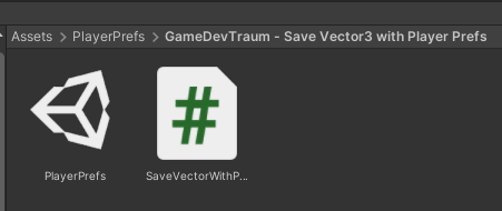
Fig. 1: Files that are added to your project when importing the download package.
Analysis on how to save a Vector3 with PlayerPrefs
The basic idea is to decompose the vector into its components that are float data and then store those components individually with PlayerPrefs, then, when loading the data, retrieve each component from memory and create a new vector using those components.
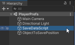
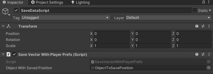
In the scene that comes in the download package the solution is already assembled, in figure 2 we see how the hierarchy is composed, we have a GameObject called “SaveDataScript” which is the one that has assigned the Script that we are going to analyze (see figure 3) and this is responsible for saving and loading data. Then we have another GameObject called “ObjectToSavePosition” that is a cube to which we will save its position to be able to load it when starting the scene. Notice that in the inspector in figure 3, our Script has a reference to this object, this will allow you to read and modify its variables or execute functions on this GameObject,
Fig. 2: GameObject of the scene that will contain the script to save and load a Vector3 in Unity.
Fig. 3: Script to save and load a Vector3 in Unity seen from the inspector.
Script that is responsible for saving and loading the vector
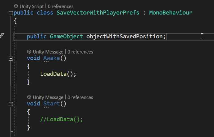
In figure 4 we see a part of the data saving script that comes in the package, we can see the GameObject type variable called “objectWithSavedPosition” that appears in the inspector in figure 3 and also the Awake and Start methods, which are functions use for initialization that Unity executes automatically at different times within the life cycle of the application. Inside the Awake function is executed a custom function called “LoadData” which is responsible for loading the information, this “LoadData” function is defined by ourselves, we see it later.
The data loading is something that normally happens when starting a scene, sometimes problems can arise depending on where the data loading is done, remember that the Start functions are executed one after another for each GameObject in an order that we can not predict or that would be tedious to predict, imagine that a Script in its Start function uses variables from another Script that has not yet loaded its data!
Fig. 4: Script to save and load Vector3 in Unity, variables and initialization.
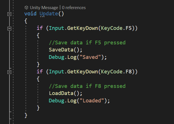
En los juegos se suelen tener atajos para guardado y carga rápida, en la figura 5 tenemos unas instrucciones que hacen precisamente esto, noten que al presionar F5 se ejecuta una función llamada “SaveData” que se encarga de hacer el guardado, sería conveniente que el guardado de todas las variables necesarias se haga dentro de esa función o que en el interior se llamen a otras funciones que se encarguen de guardar otros datos, de esa forma una vez que ejecutamos la instrucción SaveData estamos seguros de que toda la información se ha guardado, lo mismo para la función “LoadData” que se encarga de leer los datos guardados en la memoria e inicializar las variables con esos datos.
In games we usually have shortcuts for saving and fast loading, in figure 5 we have some instructions that do just this, notice that when pressing F5 a function called “SaveData” is executed that is in charge of saving all the relevant information and the same for the “LoadData” function when pressing F8.
Fig. 5: Functions for testing the saving and loading of a Vector3 in Unity.
Example on how to save a Vector3 using PlayerPrefs
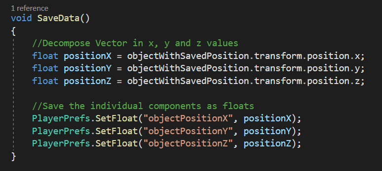
Figure 6 shows the content of the SaveData function, which is responsible for saving the vector data that will later allow us to reconstruct it. Note that first a decomposition of the vector to be saved is made in its X, Y and Z variables, which are stored in the temporary variables “positionX”, “positionY” and “positionZ”.
The saving of data with PlayerPrefs is done in the last three instructions, using the “SetFloat” function from PlayerPrefs,note the name that is passed as a label of these saves, these names must be used in the data load to retrieve them.
Fig. 6: Instructions to SAVE a Vector3 data type with PlayerPrefs in Unity.
Example on how to load a Vector3 using PlayerPrefs
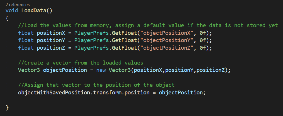
Figure 7 shows the content of the LoadData function that is responsible for loading the data stored in memory and make a reconstruction of the vector, the load is the reverse process, first we retrieve the data from memory, we do this with the “GetFloat” function from PlayerPrefs, passing the label that was used for each data and in this example I include the value 0 in case there is no previously stored information, this allows us to call it directly in Start or Awake and to make sure there are no conflicts the first time the application is run.
The next instruction is in charge of creating Vector3 from the data retrieved from memory. Vector3 and in general most classes have constructors that allow us to create the data by giving them initial values, we use that constructor with the “new” keyword.
The problem does not end here, as we have read the information, create the vector but we have not yet told our GameObject to position itself on that Vector3 coordinate, this is done in the last instruction in Figure 7.
Fig. 7: Instructions to LOAD a Vector3 data type with PlayerPrefs in Unity.
Introduction
In this article we will see how to set up a Unity project to create builds for Meta Quest 2, for this we will use the “Oculus Integration SDK” package for Unity which contains everything you need to start creating virtual reality apps for Oculus, it also comes with 3D models and useful examples. Let’s go through each necessary configuration, create a build and run it on an Meta Quest device.
All the IMPORTANT information is summarized in the following TUTORIAL FROM MY YOUTUBE CHANNEL
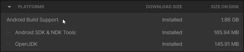
In order to compile applications for Meta Quest you need to have the Unity engine installed with the Android modules, which consist of the following three applications:
Fig. 1: These modules installed in Unity HUB are required to compile for Meta Quest.
Let’s download and import the Oculus Quest SDK package for Unity which comes with many useful Assets that will help us to create VR applications for Oculus.
Oculus Developer HUB allows you to recognize the Oculus device from your computer, configure it, access to captured images and videos, and publish applications to the Oculus Store.
The Oculus app allows us to use PC virtual reality applications with our Oculus, which can be done via cable or with the AirLink connection.
How to configure Unity to export applications for Meta Quest (Oculus Quest)
Now let’s see what parameters we have to configure in the Unity engine to be able to export for Oculus, for this we will create a new project and see the step-by-step.
Set Android platform as build target
Oculus Quest devices use Android as the operating system so first let’s go to File > Build Settings and change the target platform to Android, as seen in Figure 2.
Fig. 2: Changing the target platform for compilation.
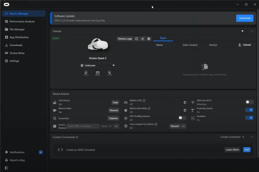
In this case I am going to use the Oculus Quest 2 device, with the device connected I open the Oculus Developer HUB application to check that the operating system recognizes the device, if we are successful we should see our device as in figure 3.
Fig. 3: Device window of the Oculus Developer HUB program.
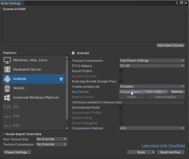
Also in Unity, in the Build Settings tab you should see the device in the “Run Device” field, as shown in Figure 4. If you do not see the device you have to go back to the prerequisites part, probably you have not enabled developer mode or you have to enable USB debugging inside the Oculus device.
Fig. 4: The connected device is displayed in the Build Settings window.
Import of the Oculus SDK package for Unity
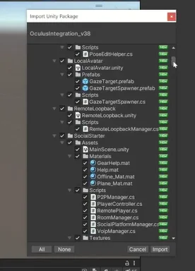
Import the Oculus SDK package (download link at the top of the prerequisites). In this case we are going to add all the files that come in the package.
Fig. 5: Window to import the Oculus SDK package for Unity.
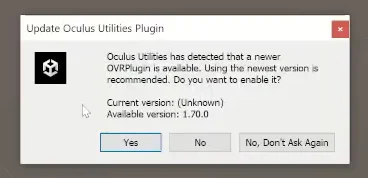
At this point, several dialogs appear asking us how we want to proceed.
In general for all messages I choose the recommended and most up to date options, in the case of figure 6 we click on “Yes”, in the case of figure 7 we click on “Use OpenXR”.
Fig. 6: Message that appears when importing the Oculus SDK package.
Fig. 7: Message that appears when importing the Oculus SDK package.
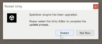
You may be prompted to restart the Unity editor, in which case restart the editor.
Fig. 8: Message that appears when importing the Oculus SDK package.
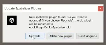
Figures 9 and 10 are another example of messages that may appear, I apply the same criteria, choose the most up to date options and restart if necessary.
Fig. 9: Message that appears when importing the Oculus SDK package.
Fig. 10: Message that appears when importing the Oculus SDK package.
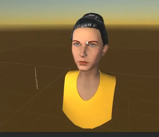
At the time of recording the video and writing this article, when going through the whole process of configuring the Oculus SDK package for Unity, after restarting the editor for the last time an example scene opens showing an Avatar with LipSync (lip sync with microphone input, Figure 11). We are going to compile this same scene so we open the Build Settings tab (under the File tab) and click on the “Add Open Scene” button to add the open scene to the compilation we are going to create.
Fig. 11: Example scene that opens when Unity is restarted.
Fig. 12: The open scene is added to the compilation.
Setup of the XR Management plug-in
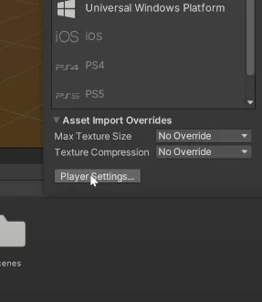
The next step of the configuration is to go to the “Player Settings” window, we can do it from “Edit” and we also have a shortcut from the Build Settings window as shown in figure 13.
Fig. 13: Shortcut to the Player Settings window to configure compilation parameters.
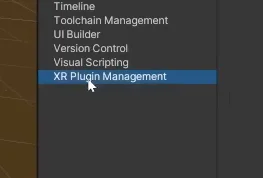
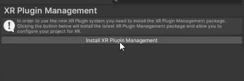
In the Player Settings window go to the “XR Plugin Management” item and click on the install button shown in Figure 15.
Fig. 14: Section XR Plugin Managment in Unity.
Fig. 15: Installation of the XR Plugin Plugin Managment in Unity.
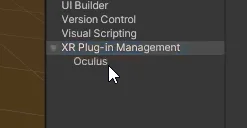
Once the plugin is installed, click on the “Oculus” checkbox that appears and this action causes a new element called Oculus to appear below the plugin (figure 17), click on the Oculus element.
Fig. 16: Activate the Oculus checkbox of the Plugin.
Fig. 17: Go to the new Oculus tab of the Plugin
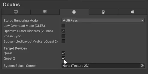
We make sure that the Quest and Quest 2 checkboxes are checked so that the plugin is applied to these devices.
Fig. 18: Make sure that the Quest and Quest 2 boxes are checked.
Configure appropriate Color Space
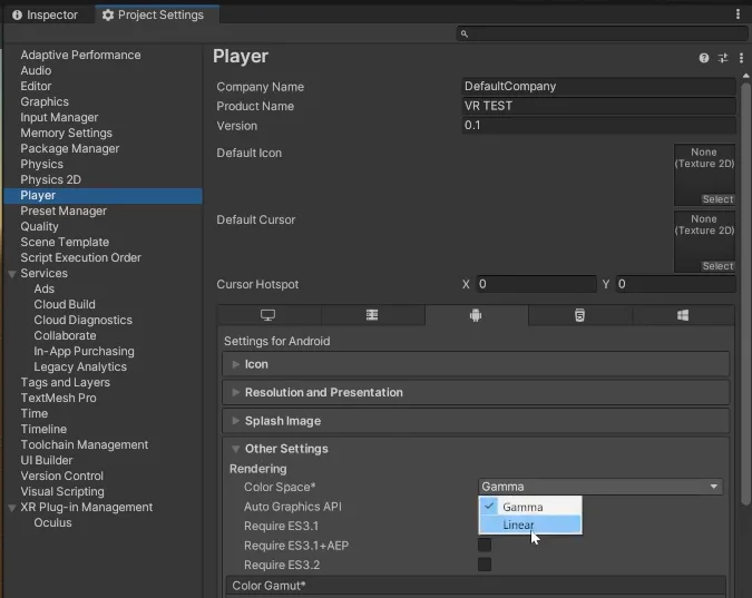
Before compiling an application for Oculus Quest in Unity we have to make sure to change the “Color Space” parameter found in the Project Settings/Player window and within the “Other Settings” drop-down menu, as shown in Figure 19. If this step is not done we will have errors in the console when compiling the application.
Fig. 19: Changing the Color Space parameter to Linear in order to compile for Oculus.
Virtual reality application compilation and testing in Meta Quest 2
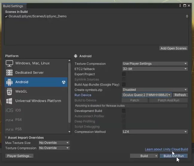
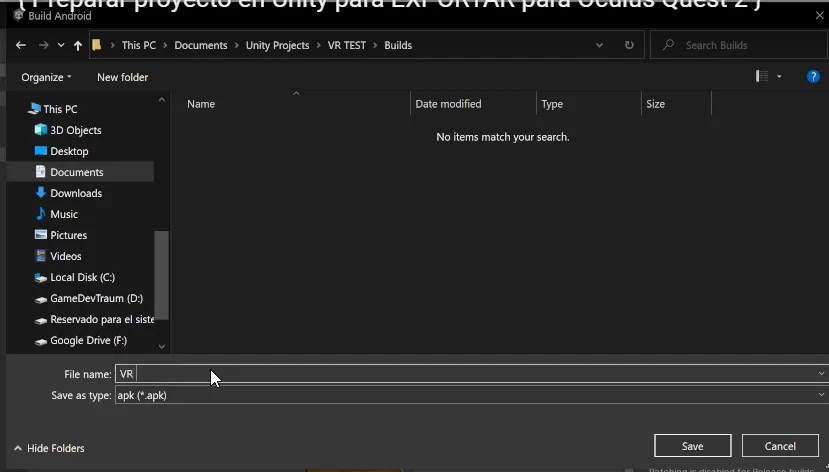
Once we have configured everything in the Unity engine we proceed to create a build of the virtual reality application and test it on a device such as the Oculus Quest 2, for that we go to the Build Settings window and making sure that in the “Run Device” parameter we have our device (make sure the device is connected via USB or AirLink), we click on Build and Run, choose the destination folder of the APK file and give it a name, as shown in Figures 20 and 21.
IMPORTANT: If the device does not appear in the “Run Device” field you can click the Build button, export the APK file and then install that file via the Oculus Developer HUB software by dragging the APK file to the window shown in Figure 3 at the beginning of this article.
Fig. 20: We create the compilation for Oculus by clicking on Build and Run.
Fig. 21: We name the APK file to compile.
When the process finishes the application runs automatically on the Oculus Quest 2 device, the result of this is shown in the following image:
Fig. 22: Test of the example scene in Oculus Quest 2.
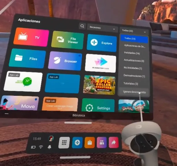
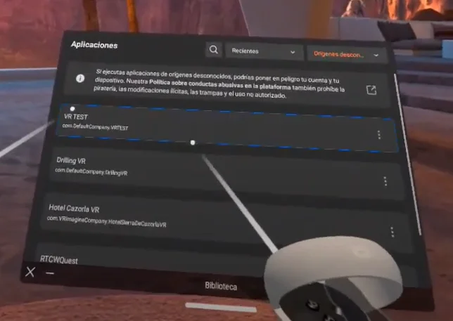
Where is the Unity application installed on Oculus
As we are doing a test, this virtual reality application was not validated by the Oculus store and therefore our device places it in a separate section of applications with “Unknown origins”, in that section we can find the application that was installed from Unity, see figures 23 and 24.
Fig. 23: The test applications build from Unity are located in the “Unknown Origins” section.
Fig. 24: Virtual reality application for Oculus Quest 2 compiled with Unity.
For the applications to appear in the main section we must upload them to the oculus store.
Introduction – What is Occlusion Culling in Unity?
The Unity engine has a system called “Occlusion Culling” that allows to automatically hide objects that the camera is not seeing directly. In this article we are going to see how to prepare a project in Unity so that Occlusion Culling is applied, some details about its operation and configuration parameters.
Important Detail – Pre-calculations (BAKE) are made in Occlusion Culling
Occlusion Culling works with objects that are marked as “static” in the scene and it is necessary to pre-calculate all the data, this is known as “bake”, this implies that every time you introduce a new object that should be turned off if the camera is not seeing it, or if you change the position of one of these objects, you must precalculate again the data for Occlusion Culling, if you don’t do it some objects that are behind the camera or behind some object may not disappear or even worse, you could have objects that disappear in front of the camera when they should remain visible.
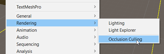
Where is the Occlusion Culling configuration window in Unity?
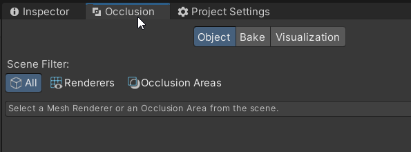
The Occlusion Culling configuration window is located in Window > Rendering > Occlusion Culling, in my case I usually place it next to the inspector window for convenience, as shown in image 2.
Image 1: How to open the Occlusion Culling window in Unity.
Image 2: Occlusion Culling window next to the inspector in Unity.
How to add objects to the Occlusion Culling system in Unity
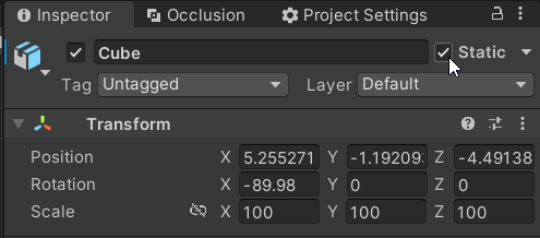
For an object to belong to the Occlusion Culling calculations and therefore disappear when the camera is not looking at it, each object must be marked with the “Static” parameter in the inspector, as shown in image 3. In general, the important objects to mark as static are those that have some kind of Renderer component assigned to it, such as a Mesh Renderer component or a Sprite Renderer component, since these objects are the ones that have a visual representation on the screen.
Image 3: “Static” property of any GameObject that allows to include it in the Occlusion Culling system.
IMPORTANT: Objects that are part of the Occlusion Culling system must not change position at any time and if they do, the data must be recalculated as we will see below.
How to apply Occlusion Culling in Unity
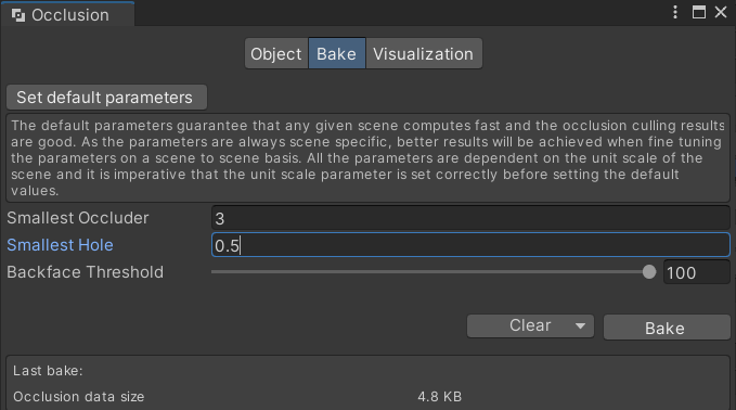
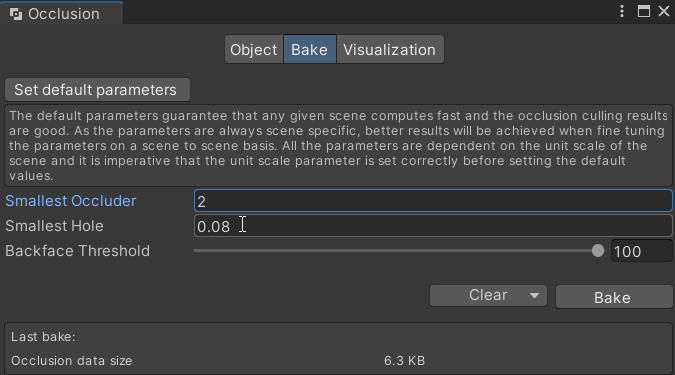
Once the previous step of marking all the static objects we are going to make a “Bake” of the information to apply Occlusion Culling, for this we go to the “Occlusion” window that is observed in image 4, in case of not seeing the window consult above in this article.
In this window basically we are going to configure two parameters, “Smallest Occluder” and “Smallest Hole”, the first parameter refers to the smallest object in the scene (in scene units) that can obstruct the camera and make everything behind it not to be rendered, the smaller this parameter is the longer the calculations will take so we will have to do some tests to determine an appropriate value, in principle we can consider the values of the image 4.
TO APPLY THE OCCLUSION CULLING CALCULATIONS IN UNITY CLICK ON THE BAKE BUTTON TO THE RIGHT OF THE CLEAR BUTTON
Image 4: Occlusion window to apply Occlusion Culling in Unity.
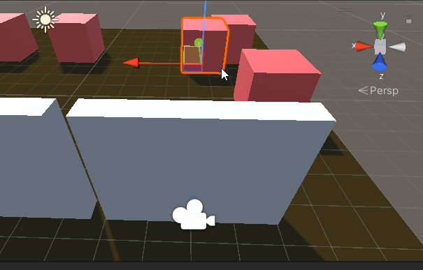
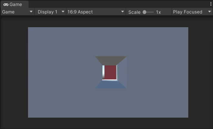
The “Smallest Hole” parameter is used in case of having open spaces in a 3D model, consider the example illustrated in image 5-A, in which Occlusion Culling has been applied with the parameters of image 4.
Image 5-A: Scene set up to illustrate Occlusion Culling.
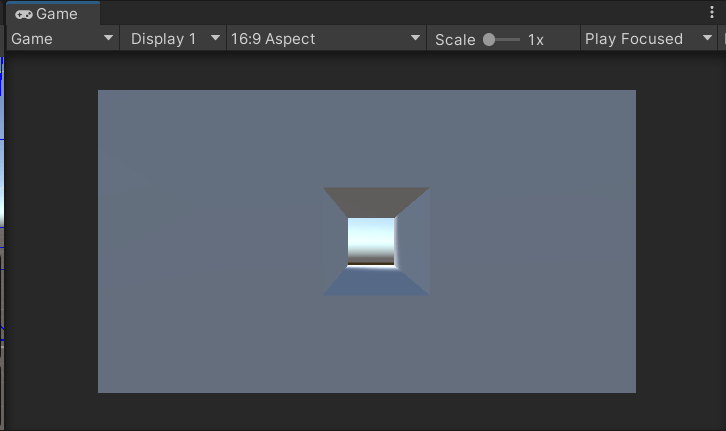
Image 5-B: Perspective of the camera in image 5-A.
As we see in image 5-B the camera can see through the hole, however the cube that is selected in image 5-A is not visible, this is because the Occlusion Culling system is considering that this cube should be hidden, since the smaller hole is set to a size of 0.5 Unity units (image 4), while the hole in image 5-B has a size of 0.1 by 0.1 Unity units.
Modifying a bit the parameters taking into account these particular models and the fact that we should be able to see objects through that hole, we make a new Bake with the parameters of image 6 and as seen in image 7 now the Occlusion Culling system does not hide that object because the camera could see it through that hole.
Image 6: New parameters to correct the problem of objects not visible through holes in Unity.
Image 7: With these new parameters the camera can see the cube through the hole.
Anne lives a peaceful life on her farm, tending to her crops and her garden. Suddenly the peace comes to an end as a large number of raccoons show up on her farm and mess up everything they find. Anne has worked very hard on her farm and does not plan to sit around and do nothing.
How to play
Control Anne by pressing the WASD keys or the arrow keys. Collect the objects with the E key. Get the farm up and running and if you have time, find the vegetables that the raccoons messed up. Each station is normalized with a particular object so you will have to have this object to scare away the raccoons and normalize the station.
Developed for the Ludum Dare 51 Game Jam with theme "Every 10 seconds" by:
Mc. Rooties is looking for a kitchen assistant to replace their former employee who is rumored to have fled in tears and screaming out the back door of the restaurant. Your exceptional knife skills have made you a name for yourself and you are the right person for the job.
How to play
Control the knife by moving the mouse and cut the roots at the point indicated by a red line, the knife only cuts with a quick movement, be careful not to damage the vegetables.
Developed for Global Game Jam 2023 with the theme "Roots" by:
CIAN
ILUSTRATOR
MANU
GAME DESIGN
VALEN
UNITY DEVELOPER
GAMEDEVTRAUM
UNITY DEVELOPER
MR. DORIAN
MUSIC COMPOSER
AGRAULIS.C
ILUSTRATOR
This website uses cookies to improve your experience. We'll assume you're ok with this, but you can opt-out if you wish. Cookie settingsACCEPT
Privacy & Cookies Policy
Privacy Overview
This website uses cookies to improve your experience while you navigate through the website. Out of these cookies, the cookies that are categorized as necessary are stored on your browser as they are as essential for the working of basic functionalities of the website. We also use third-party cookies that help us analyze and understand how you use this website. These cookies will be stored in your browser only with your consent. You also have the option to opt-out of these cookies. But opting out of some of these cookies may have an effect on your browsing experience.
Necessary cookies are absolutely essential for the website to function properly. This category only includes cookies that ensures basic functionalities and security features of the website. These cookies do not store any personal information.