Introduction
In this article we are going to see how to download and install LT Spice software to simulate electrical and electronic circuits. We will also create a simple circuit to test the program.
Download the software
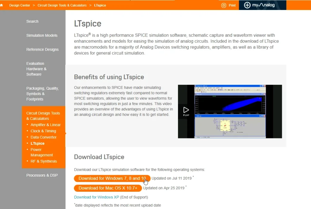
First we will download the installer from the official website, click on the link below:
LT Spice
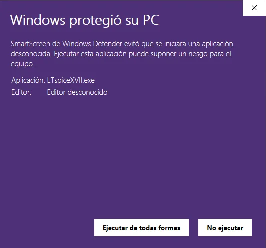
Once the download finishes we run it. In my case I got a screen saying that the installation was blocked by the Windows protection system, when I clicked on “More information” the button “Run anyway” appeared.
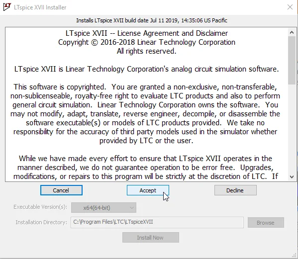
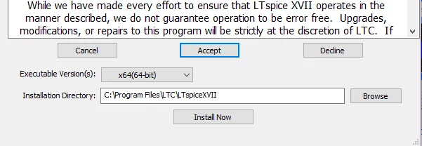
We accept the terms and conditions and choose the installation location. In my case I leave everything by default.
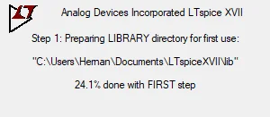
At the end of the installation the program runs automatically, the sign appears in Figure 6 saying that the program is ready to run for the first time.
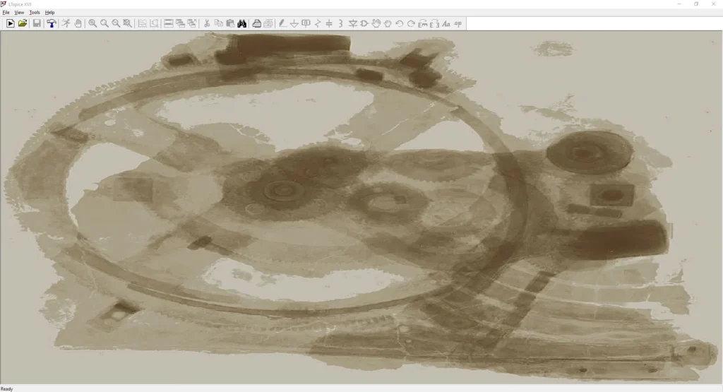
At the end of the process the main window of the program appears, and we are ready to start creating schematics and simulating electrical and electronic circuits.
Create an Schematic
Next we’re going to create a very simple circuit like the one we saw in the article about what electrical resistance is, which consisted of a voltage source and a resistance.
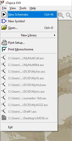
First we go to File > New Schematic, to create a new project, this can be seen in figure 8.
The workspace appears in gray, here we will begin to build the schematic.
Let’s add elements, click on the AND gate button shown in figure 9.
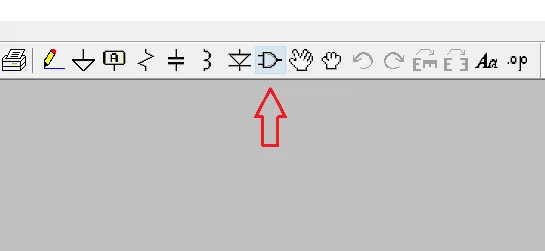
This will display a window in which we can choose the components.
Power Source
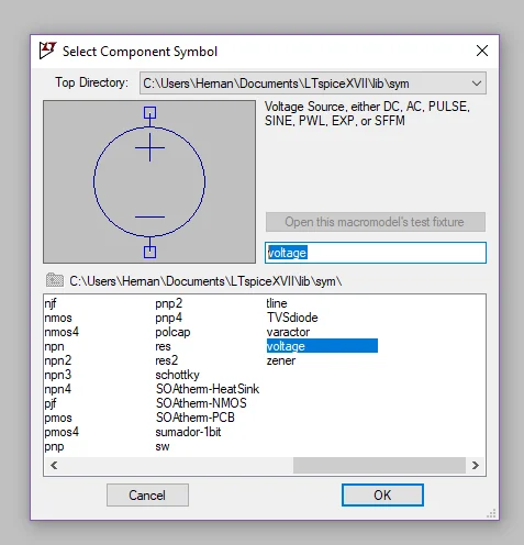
To power our circuit we are going to need a voltage source, in the search bar of the components window we write “voltage” and select the generic source that can be seen in figure 10.
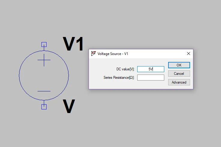
We place it in the workspace and right click on it, this will open a window to enter the parameters of the font, in my case I will use 5 Volts.
The “Advanced” button allows us to define advanced parameters of the source, such as signal type, frequency, period, duration, ascent and descent times, among others. For now we are only going to keep the DC source that comes by default.
Resistors
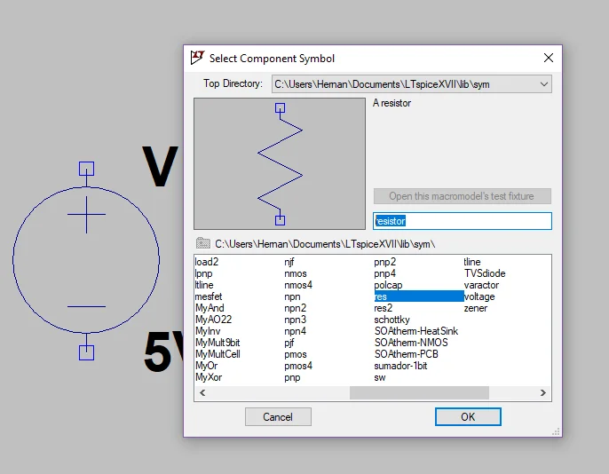
Let’s add the resistor, press the button of the AND gate again (figure 9) and this time we write “resistor” in the search bar. Select the generic resistor shown in figure 12.
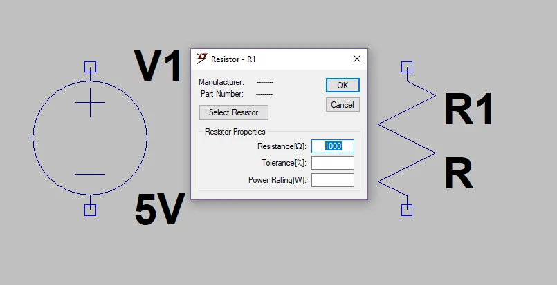
We place it in the workspace and right click on it to enter the parameters.
For now we will only enter a resistance value of 1000 (the standard unit is Ohm, as we see in figure 13 between square brackets to the left of the value 1000).
Wiring
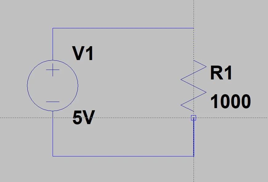
When all the elements are in place, let’s make the connections. Click on the pencil button shown in Figure 9 or use the F3 shortcut.
Then we draw the connections between the source and the resistance.
Ground
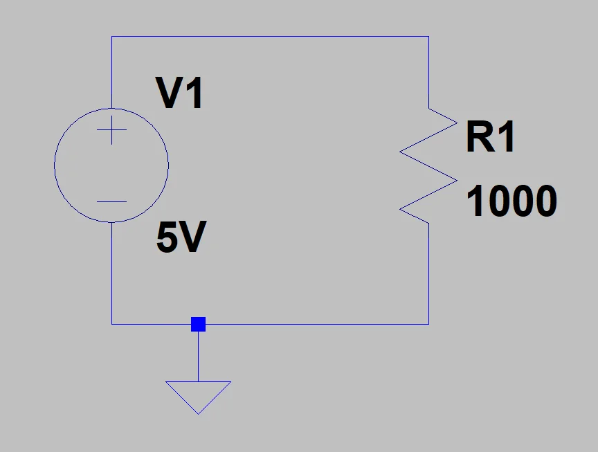
Finally, in order for the program to perform the calculations, it needs a ground point for reference. Click on the triangular button in figure 9 or with the “G” key.
We place the ground on the cable that is connected to the negative terminal of the source, as shown in figure 15.
Simulation
When we finish the schematic, we go on to configure the simulation parameters.
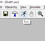
If this is the first time we are going to simulate, click on the Run button shown in figure 16. If this is not the first time, go to the “Simulate” tab and click on “Edit Simulation CMD”.
In the Edit Simulation window we are going to choose the last tab called “DC op pnt”, which is shown in figure 17.
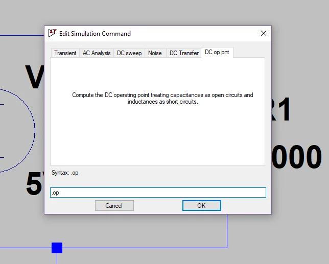
With this option the program will make a direct current calculation of the circuit, showing the voltages in all the nodes and the currents in all the branches.
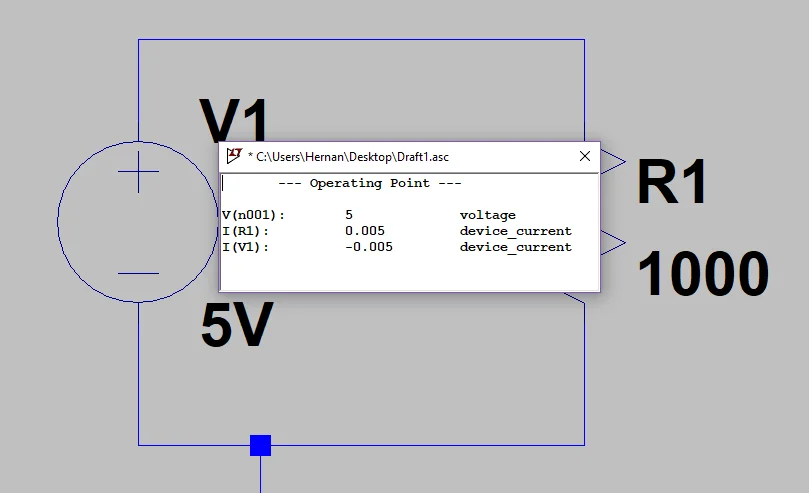
In the window that appears we can see that the current in the resistance is 5 mA, which is condiced with taking the 5 V of the source and dividing them by 1000 Ohms of the resistance, according to the Law of Ohm.
With this we finish the exercise, we are ready to simulate more complex electrical and electronic circuits. In other articles we will talk about how to draw graphs or produce other simulations.