Introduction
In this article we will see a downloadable solution that consists of a conveyor belt made in Unity, whose operation is controlled using an Arduino plate.
Downloads
In the next package you will find two folders, one with the Unity files and one with the Arduino files.
Inside the Unity folder you will find a compilation to test the simulation and also a Unity package that you can import into your project and access the assets of this simulation.
Upload the program to the Arduino
In the downloads you will find a folder called “Arduino”, which contains the program that reads the digital entries, forms a word and sends it through the serial port.
The program is quite simple so it will work on any Arduino board you can get, in my case I used an Arduino Mega.
In the following video you can see how to record the program on the Arduino board, you will need the Arduino software.
Circuit for digital inputs
The Arduino program that comes with the download uses pins 2 and 3 for the digital inputs. Pin 2 controls the status of the feeding machine and pin 3 controls the status of the conveyor belt.
There are many ways to connect signals to the Arduino’s digital input, I will show two alternatives using switches.
WARNING
BE SURE TO CONNECT THE ELEMENTS TO THE ARDUINO PROPERLY, A SHORT CIRCUIT CAN DESTROY THE BOARD.
IT IS NECESSARY TO KNOW THE LEG DISTRIBUTION OF EACH PARTICULAR CONTACT, BETTER IF YOU HAVE A TESTER TO MEASURE CONTINUITY.
Alternative 1: Two-position switch
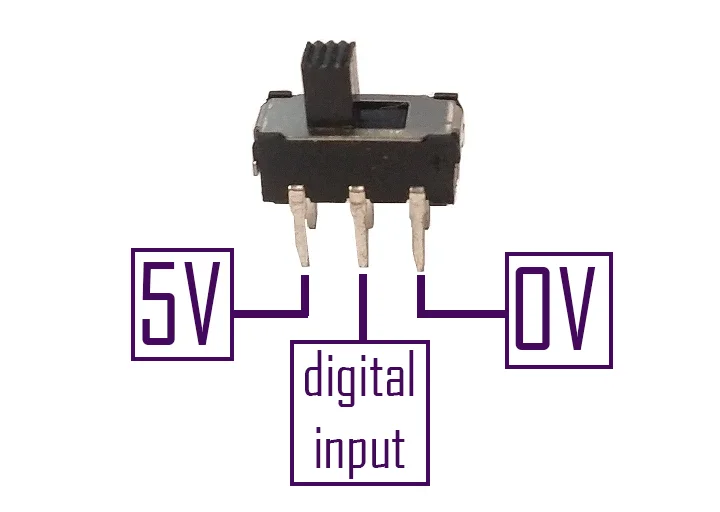
In my case I used two position switches for the digital inputs, in these switches the middle terminal makes contact with one end or the other depending on the position of the switch. Therefore, at the ends we connect the high and low voltage signals (in my case 5 Volts and 0 Volts respectively). The middle terminal of the switch is connected to the digital input of the Arduino.
I repeat the warning, the switch I used is like the one shown in figure 1 and in this particular case it is connected that way.
Alternative 2: Pull-up resistor switch
Perhaps you only have one switch, i.e. a contact that closes or opens. In the Arduino’s digital inputs there should be constant high or low voltage signals, we should not leave digital inputs unconnected to anything (connection to the air as we say here) as this will lead to unpredictable behavior.
To do this, a small circuit with a pull-up resistor must be implemented, as shown in figure 2.
In this case we use a resistor connected to the GND terminal of the Arduino and the other end connected on one side to the digital input and on the other to the switch, the other end of the switch is connected to the high voltage signal (5 Volt for example).
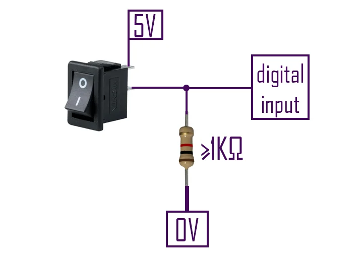
The circuit in figure 2 works as follows: when the switch is open there is no current flowing through the resistor, therefore the 0 Volts are transferred to the digital input and the Arduino reads a low level. When we activate the switch the current will flow through the resistance and the Arduino’s input will have a high level signal.
Check if the Arduino program is working
The Arduino program is in charge of reading the status of the digital inputs, creating a binary word that represents those states and sending it by serial port.
If we open the Serial monitor, from the Tools tab, we should see the states of the digital message inputs. As you can see in the following video.
Test the simulation
Once we have recorded the program on the Arduino board, we can run the compilation that comes with the download.
When entering the simulation, in the upper left corner there is a button to connect Unity to the Arduino board.
In this part you may have problems with the connection, probably correct this in another version of the solution. To make sure the connection works, the Arduino board must be connected before opening the compilation and the connection process may take several seconds to complete. If after 30 seconds the board is not connected, check the previous step and reopen the simulation and try again.
Video 3: Prueba de la cinta transportadora en Unity controlada por Arduino.
Import package and fix “API Compatibility Level” error
To access the source files of the simulation is the Unity package, you can import it as seen in the following video.
Video 4: Import bundle and fix API Compatibility Level error
When importing the package we will get errors because some scripts cannot access the package with the classes that allow access to the serial port.
To fix this, follow the steps shown in video 4. Go to Edit > Project Settings > Player > Other Settings and in the field “API Compatibility Level” set “.NET 4.x”.
How the Conveyor belt in Unity controlled by Arduino works
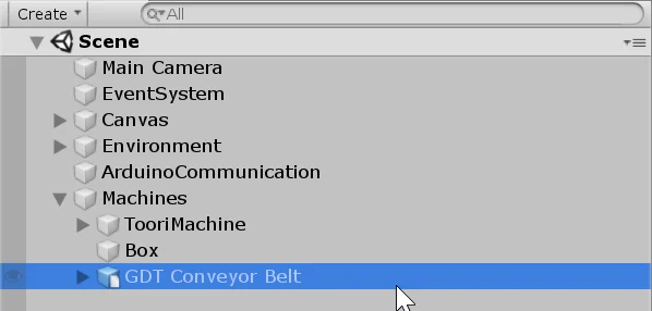
Inside the package is the scene that is seen in the simulation, we can access it and see its elements, in figure 3 we can see the hierarchy of the scene.
In the hierarchy we have three machines, “Toori Machine” is the machine that places objects on the conveyor belt. “GDT Conveyor Belt” is the conveyor belt and “Box” is the box where the objects fall and are destroyed.
Conveyor Belt
The conveyor belt is a 3D model with a structure and a belt.
To achieve the animation of the operation what is done is to add offset to the UV map of the texture. In this case, as the texture is vertically distributed, we add offset to the Y component of the UV map. When the UV map has an offset of 1 in the Y component the texture returns to the initial state.
So to achieve the effect of the conveyor belt moving forward or backward we gradually increase the UV map offset on one of the components.
To make the belt transport objects, you have a Collider box in Trigger mode that detects when an object is on the belt, these objects must have a RigidBody component assigned to them.
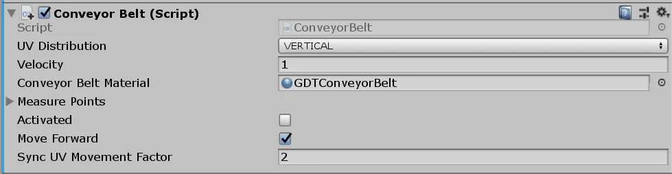
Then in the Conveyor Script you define the OnTriggerStay function that will be called when an object is on the conveyor belt. This function will be in charge of moving the object, to synchronize the movement of the belt with the movement of the object there is a parameter in the inspector called “SyncUVMovementFactor”, by default it is set to 2, as shown in figure 2.
The conveyor belt has a public function that allows it to be activated or deactivated and that can be called from any other Script. We execute this function with the information we read from the Arduino board, that is, it will be activated or deactivated according to the status of the digital input 3 of the board.
Feeding Machine
To make the simulation a little more complete, a machine that places objects on the conveyor belt is included. This machine is controlled with the “FeedingMachine” script and also has a public method that allows you to turn it on or off. This machine will be controlled with the digital input 2 of the Arduino.
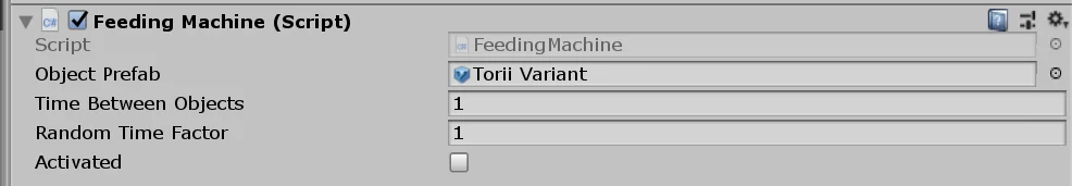
In the inspector we can place the prefab of the objects to be placed on the conveyor belt and we can change the times between one object and another.
Communication between Arduino and Unity
Esta parte se resuelve utilizando una versión modificada de la solución WRMHL compartida por el equipo RELATIVTY. Te animo a visitar los links para ver la solución original y los proyectos.
This part is solved using a modified version of the WRMHL solution shared by the RELATIVTY team. I encourage you to visit the links, see the original solution and the projects they have.
In order to communicate Unity with Arduino you must have a GameObject in the hierarchy with the “wrmhlRead” script assigned.
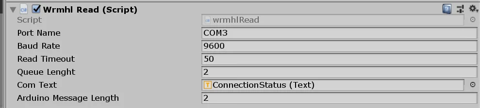
I have added an integer called “arduinoMessageLength” in the inspector, which indicates the length of the binary word that is sent from the Arduino. This is used to correctly synchronize Unity with Arduino in case there are more devices using the serial port.
In our case, since we sent a two-digit word from the Arduino, you must put two in that field. If you add more digits to the word, you must modify this field appropriately.
The reading of the Arduino message is done in the “ReadMessageAndAction()” method. Here inside we can perform the action we want in Unity. In our case we execute the public methods of the ConveyorBelt and FeedingMachine scripts, to activate or deactivate the machines according to the Arduino’s command.
Conclusion
We’ve seen how the conveyor belt solution works at Unity controlled by Arduino.
With the files provided you can create a new simulation according to your needs.