
Introduction
In this article we will deduce how to calculate the resulting resistive value by placing resistors in parallel, i.e. connecting two or more resistors with their interconnected legs. In addition we will use LT Spice to verify these results.
See also calculations with resistances in series
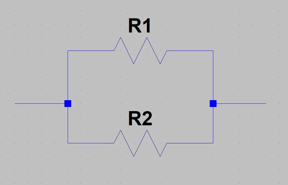
Analyzing figure 1 we can see that the voltage applied to each resistance is the same for all, what will generate a current in each of these, the total current of the source will be the sum of the currents by all the branches of the resistances.
Deduction
To begin the deduction let’s assume a simple circuit consisting of a V voltage source connected to the parallel resistor array, like the one illustrated in Figure 2.
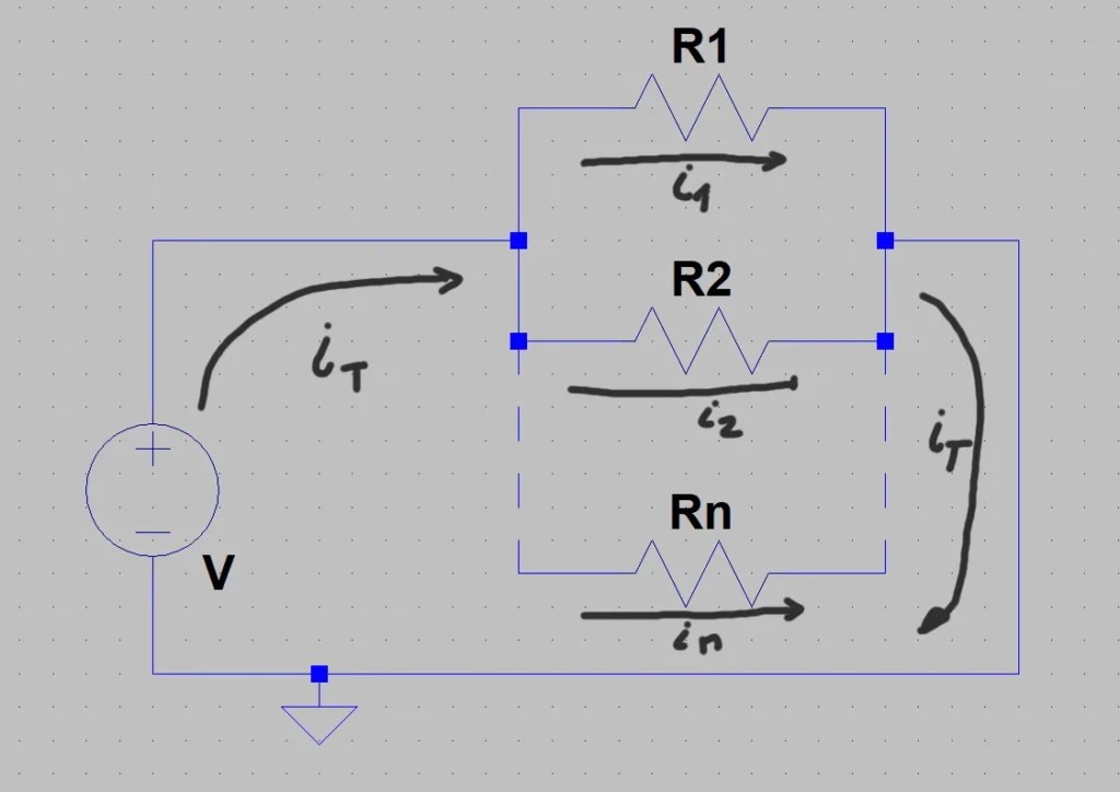
On this circuit we are going to apply Kirchoff’s circuit Law for current, which tells us that a node the sum of all the currents that enter the node is equal to the sum of all the currents that leave the node. We consider as node a point that is between the voltage source and the union of all resistances.
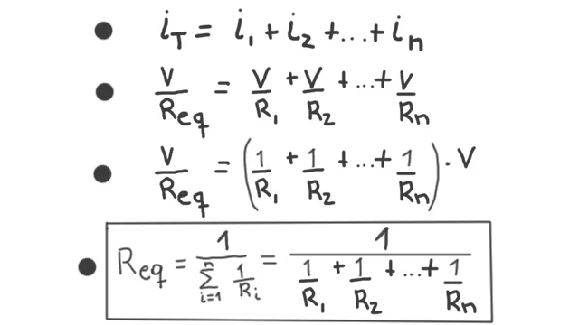
In figure 3, in line 1 I have written what this law tells us considering that we have a finite number of resistances.
On line 2 I place the value of the currents in terms of voltage and resistance according to Ohm’s Law. The next step is to take out the voltage v as a common factor, since all resistors have the same voltage v applied.
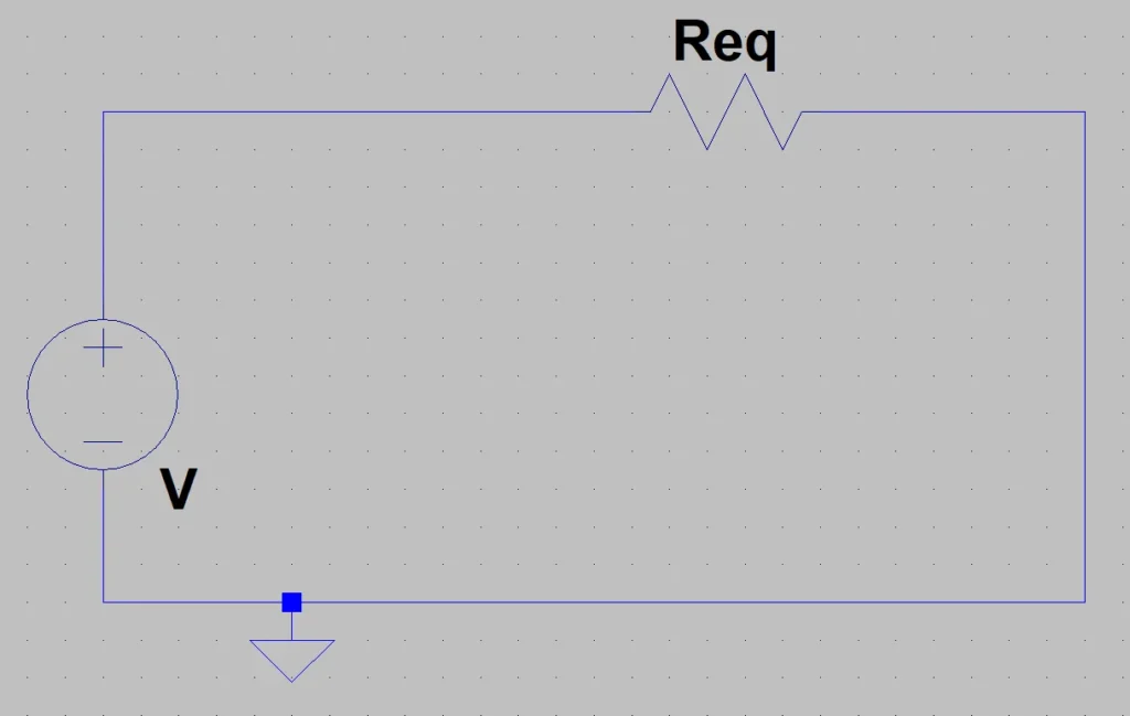
Finally we conclude that what is in parentheses on line 3 is the value of a resistance for an equivalent circuit that instead of having n resistors has only one with this value. In figure 4 we see this equivalent circuit.
LT Spice Simulation
Let’s put together a simple circuit in LT Spice to show that this result is met. If you don’t have LT Spice installed I invite you to read this article in which I show you how to download it, install it and create a simple circuit.
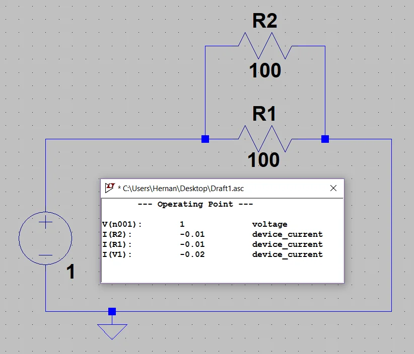
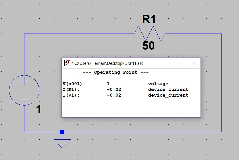
In figure 5 we have simulated a circuit with a voltage source of 1 Volt and two resistances of 100 Ohm connected in parallel, while in figure 6 we have a circuit with the same voltage source but only a resistance with the equivalent resistance value that would be 200 Ohms.
As can be seen in the posters with the result of the simulation, the current circulating through the voltage source is the same in both cases, so we can conclude that these circuits are equivalent.
Conclusion
We have analyzed a circuit with generic parallel resistances and applied the current laws to determine an equivalent expression of resistance.
When we have arrangements of resistances in parallel we know that these have applied the same tension in their extremes, applying Kirchoff’s circuit laws we can deduce an expression for the equivalent resistance.
Finally we have made a simulation to show that we can think of an equivalent circuit grouping the resistances.