
Introduction
A resistive voltage divider is an arrangement of two resistances in series that allows us to have at the midpoint a fraction of the voltage at the ends.
Applications of a resistive divider
The divider with potentiometer is usually used as an analog input in the frequency driver of the motors. Using the potentiometer we change the speed of the motor.
A BJT transistor can also be polarized with a splitter, connecting the central point of the splitter to the base of the transistor.
Working principle of the resistive divider
In figure 1 we see an arrangement that can be used as a divisor.
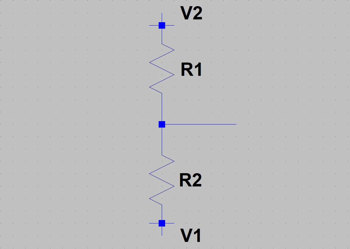
To understand how it works we must consider the potential drops in both resistances.
The voltage drop on a resistor is the current flowing through it multiplied by the resistive value.
LT Spice simulation
To see how a resistive splitter works let’s do a simulation using LT Spice. If you need help getting started with LT Spice go to this article where I explain how to install it and make a simple circuit to simulate.
We are going to analyze two cases, when the resistances are equal and when one is greater or less than the other.
Case 1: Equal Resistors
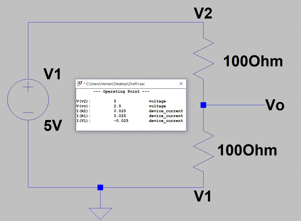
In this case we can intuit that the potential drop in both resistances will be the same (because the same current circulates through them and their resistive value is equal), therefore at the midpoint of the divisor we will have a voltage value equal to the mean value between the potential difference at the extremes.
In figure 2 we can see that the voltage in Vo is 2.5 Volts, half of the 5 Volts applied in the divisor.
With this result we may be tempted to say that the voltage at the midpoint of the divisor is going to be equal to half the value applied in V2, but this is not always the case.
This is only fulfilled if in V1 we have applied 0 Volts (in figure 2 V1 is grounded).
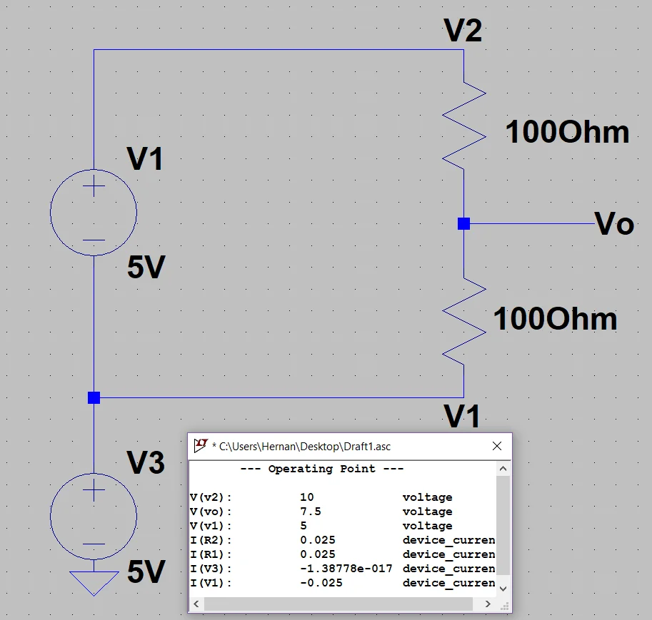
In figure 3 we see an example in which this is not fulfilled, in this case the potential difference in the divisor is still 5 Volts, but V1 is not grounded but has applied 5 Volts while V2 has 10 Volts.
The result is that in Vo we have half the applied potential difference plus the voltage V1.
Case 2: Different Resistors
In figure 4 we consider R1 smaller than R2 and in figure 5 the opposite case.
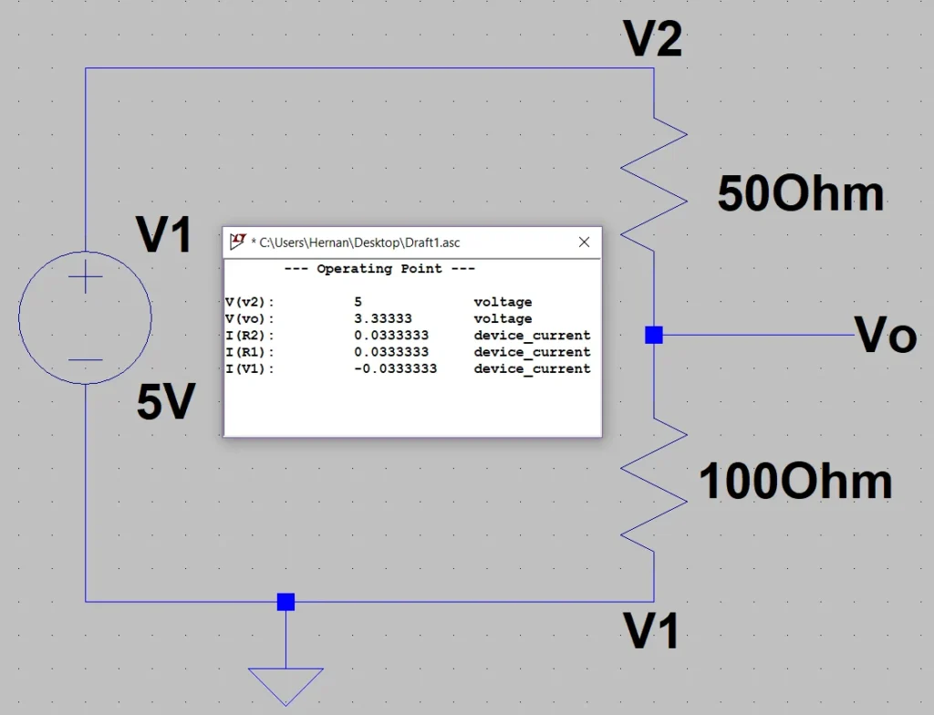
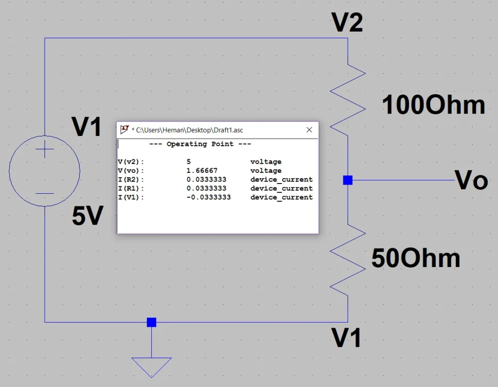
Based on the results we can say that if 100% of the resistive value is 150 Ohms, 50 Ohms and 100 Ohms will be approximately 33% and 66% respectively.
These percentages seem to be reflected in the Vo voltage, as in Figure 4 the 3.3 V voltage is approximately 66% of 5 V while 1.6 V is approximately 33% of 5V.
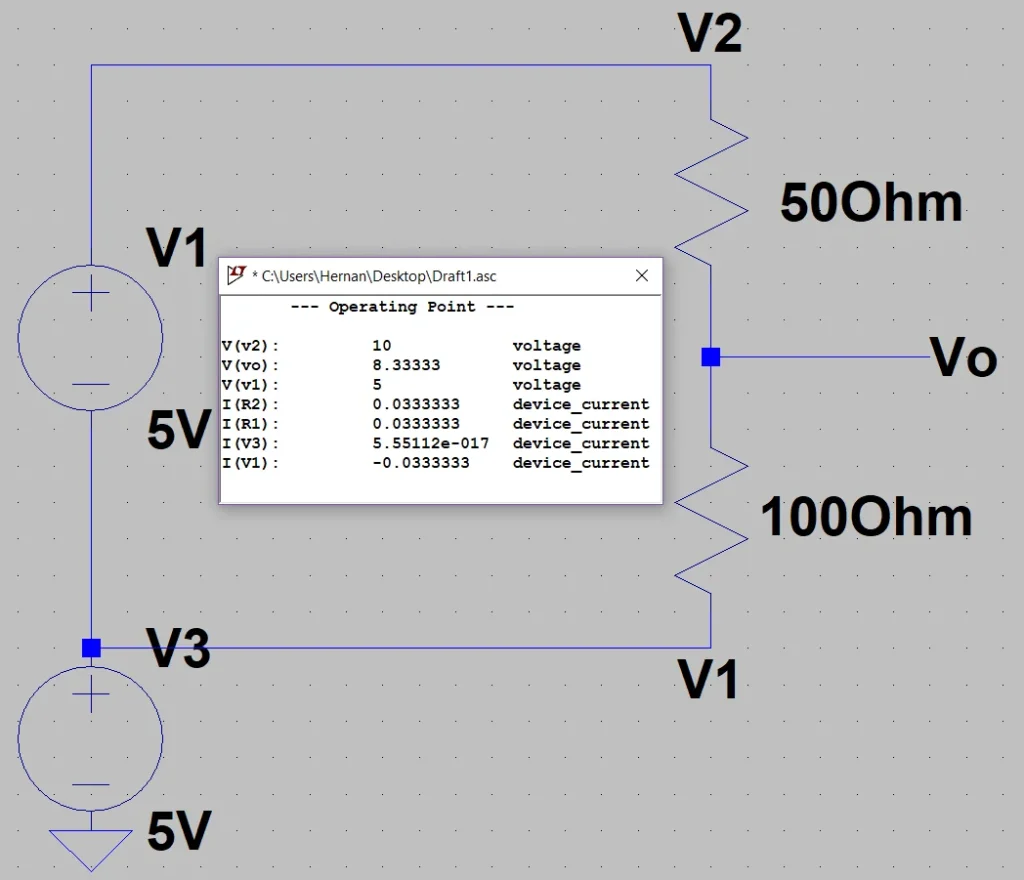
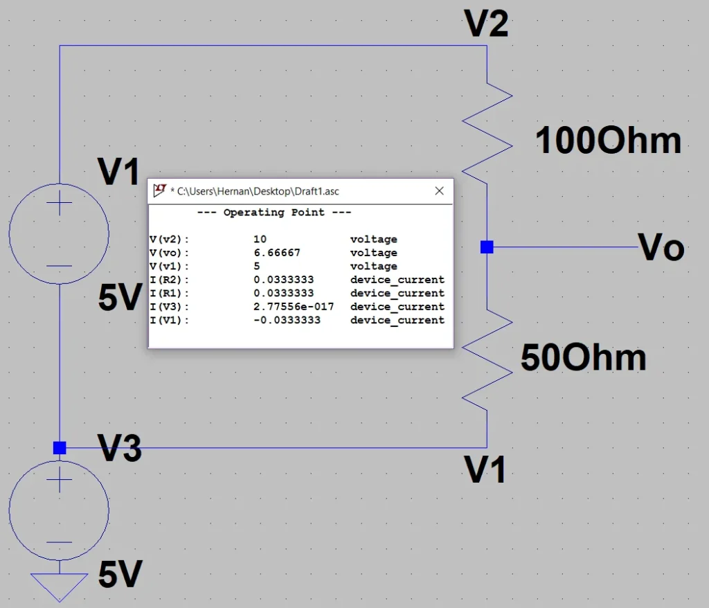
Analogously to figure 3, we should not assume that this will always be so, we must remember to add the voltage applied in V1, we can see this in figures 6 and 7.
Formula deduction
Now that we have seen the working principle and some experiments we are going to find an expression for the voltage Vo that takes into account both resistances.
The voltage Vo will be equal to the voltage V1 plus the potential drop in resistance 2.
Vo = V1 + Vr2
The potential drop in R2 is equal to the current flowing through the resistance multiplied by the value of R2.
Vr2 = i x R2
Then:
Vo = V1 + i x R2
The current circulating through the divisor, by Ohm’s Law, is equal to the difference of potential applied at the ends divided by the sum of the resistances.
i = ( V2 – V1 ) / ( R1 + R2 )
Replacing the current in the previous expression we have:
Vo = V1 + R2 x ( V2 – V1 ) / ( R1 + R2 )
Here we already have an expression for Vo in which are all the variables of figure 1, however we can solve the sum and obtain a more compact expression.
Vo = ( R1 x V1 + R2 x V2) / ( R1 + R2 )
The Potentiometer
This element can be used as a variable resistive divider.
The potentiometer is basically two resistors that we can change value but the sum of both remains unchanged.
If we connect a potential difference at the ends, in the middle we will have a voltage that will be between the minimum voltage and the maximum of that potential difference.
Using the knob we can control the voltage in the central leg.
Conclusion
We have seen what a resistive divider is and what its working principle is.
Some applications can be to enter values in analog inputs of different control devices such as frequency inverters or logic controllers. Polarize transistors.