
Introduction
Without a doubt a useful tool at the time of making tests of operation in the circuits is the Protoboard. In this article we are going to see what it is, sizes, accessories, internal connections and we are going to see examples of incorrect connection and correct connection of elements.
Before we move on:
Usually before implementing an electrical circuit, a schematic and simulation are done to verify that everything is working correctly and to make improvements. In this page we are going to use LT Spice to simulate circuits, click here to read the article explaining how to download and install this software.
Protoboard
As we see in figure 1 is a plate that has a lot of holes where we can place our components.
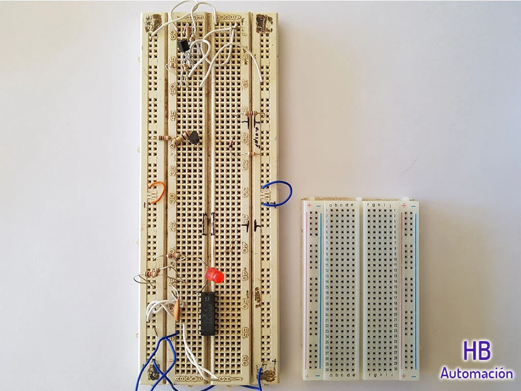
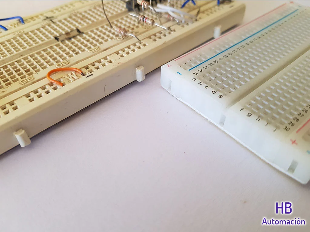
Depending on the circuit that we want to implement we may need more than one Protoboard, it is good to know that most have sockets on their sides to fit plates of the same manufacturer.
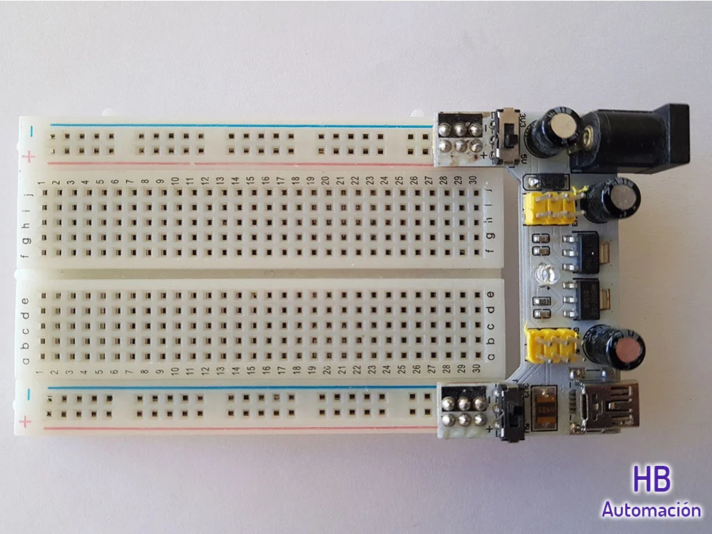
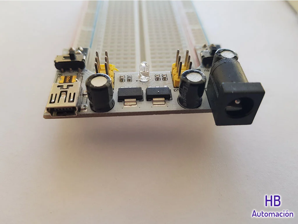
In addition in the market we can find certain accessories that we can use in the protoboard, like cables with male terminals and DC sources.
In the figures 3 and 4 we see an example of these sources that come prepared to place in the protoboard. We can feed it with transformer or with USB cable and train two switches that allow us to choose between 3.2V and 5V.
Pin Distribution
In figure 5 I have highlighted with colors to show how the electrical bridges under the dot matrix are made.
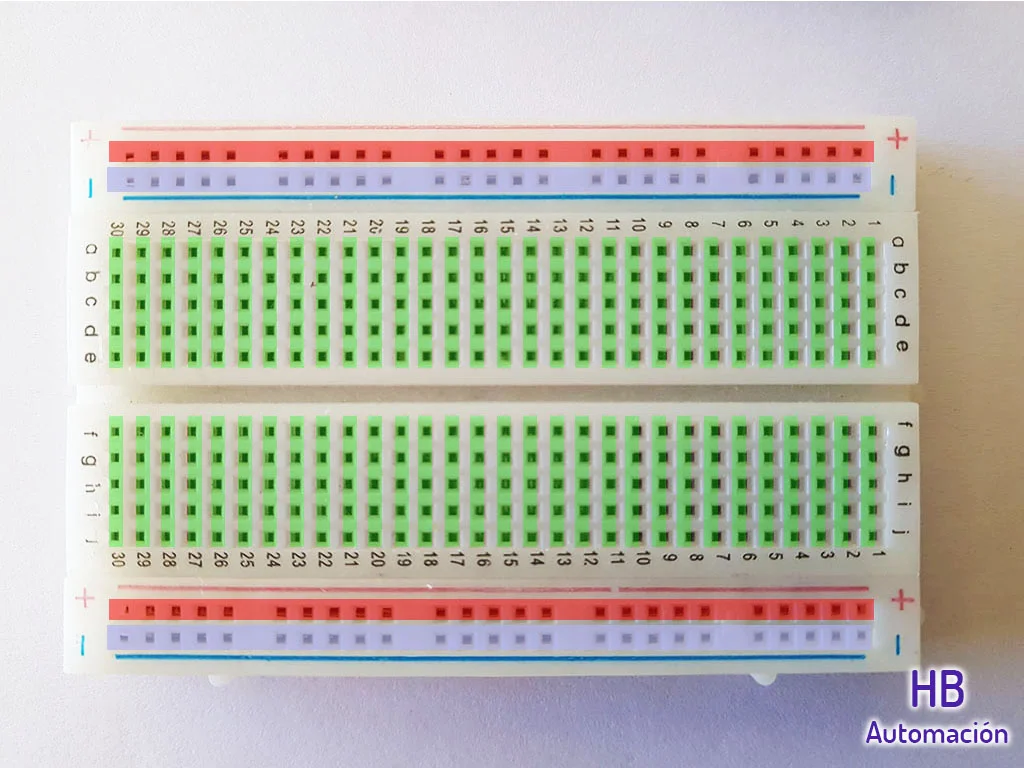
At both ends of the board we see a red line indicated with a sign “+” and another blue with a sign “-“, these lines are used to provide voltage to our circuits.
In the middle in green color we have 60 lines of 5 points that we can use to make the interconnections of our circuit.
The 5 points on each line are bridged together under the board, which helps us reduce the amount of cables we need.
Another important detail is that we have numbers for the rows and letters for the columns so that we can identify each point of the Protoboard, for example A-1 is the first point at the top right in Figure 5 and J-30 is the last point at the bottom left.
How to connect elements in the Protoboard
When we have devices with several legs such as transistors or integrated circuits, it is important that we know what the internal distribution of bridges is like, otherwise we can make a mistake in the way they are connected.
In figure 6 we see examples of current and incorrect connections.
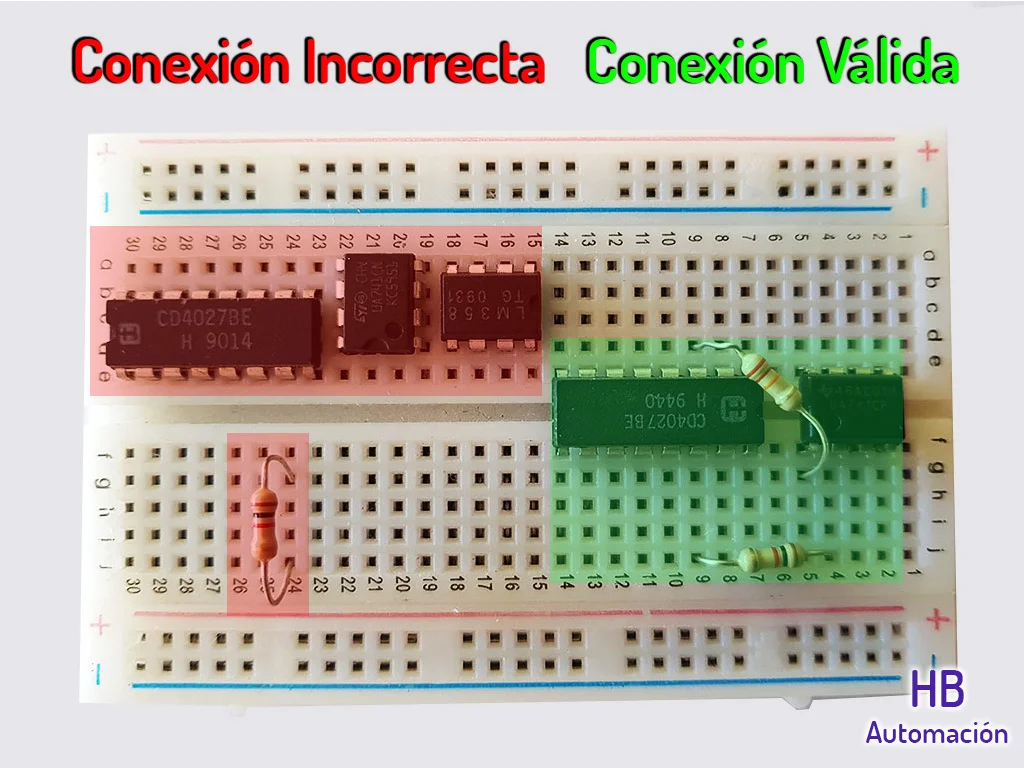
For example take the case of the resistance connected at points G-24 and J-24, the 5 points on line 24 from the letter F to J are bridged to each other, so it makes no sense to connect a resistance at two of these points, the current will never flow through it.
Conclusion
The protoboard is a useful tool when testing the operation of our circuits.
Depending on the project, we will need larger or smaller plates, it is good to know that plates of the same type can be fitted using the side skirtings and that there are accessories that can facilitate the supply and connections of the elements.
It is important to know the distribution of the internal bridges of the plate, in this way we will avoid placing the elements badly.